
Chapter 4
Polymesh Editing
As you become more comfortable shaping your creations using the sculpting brushes, no doubt your projects will become more ambitious. ZBrush gives you a number of ways to edit your mesh so that your fantastic ideas are easier to realize. This chapter explores ways to edit, organize, and expand sculpts using selection brushes, polygroups, and subtools.
In addition to these techniques, this chapter introduces the ZSphere, ZBrush’s unique armature tool, and ZSketching, which is a mesh-creation method that can be applied directly on a ZSphere armature or an existing mesh using special sculpting brushes.
This chapter includes the following topics:
- Using selection brushes
- Working with polygroups
- Using the SliceCurve brush
- Appending subtools
- Using SubTool Master
- Working in the SubTool subpalette
- Creating an armature using ZSpheres
- Creating a ZSketch
Selection Brushes
In Chapter 3 you learned how you can apply a mask to a surface in order to protect specific areas from changes. Selection brushes are an even more powerful way to accomplish this and can be used with masking techniques to focus on a specific part of the model.
As you’ve seen, ZBrush reserves a few hotkeys for specific brushes. The Shift key is reserved for smoothing brushes, the Ctrl key is reserved for masking brushes, and the Alt key is the “opposite” key, meaning that it inverts the action of the current brush. The selection brushes are mapped to the Ctrl+Shift key combination. So when you want to select specific polygons of a mesh, you hold the Ctrl and Shift keys together, which activates the brush in the Brush palette, and then while holding the keys you drag a selection marquee on the canvas and then let go. The polygons within the selected area remain visible while the unselected polygons are temporarily hidden. But of course there’s more to it than that. This section goes into more detail about how to use the selection brushes and the many options available for customizing your selections.
Selecting Parts of the Dragon’s Head
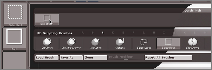
There are two selection brushes: SelectRect and SelectLasso. The main difference is the stroke type applied to the preset. You can modify the way the brushes behave by choosing additional stroke types.
Let’s look at how these brushes work. For this exercise you can use the dragon model you created for the previous chapter, or you can open the Dragon_Chapter4.ZPR project found on the DVD that comes with this book.
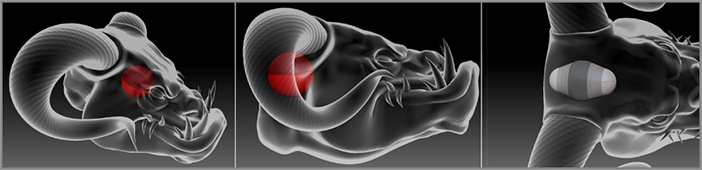
This model has been “dynameshed” into a single mesh (see Figure 4-1). As you can see, it has become a fairly complex shape considering it started as a sphere! Let’s see how we can select just the front part of the muzzle.
Figure 4-1 : The dynameshed dragon’s head is a single surface.
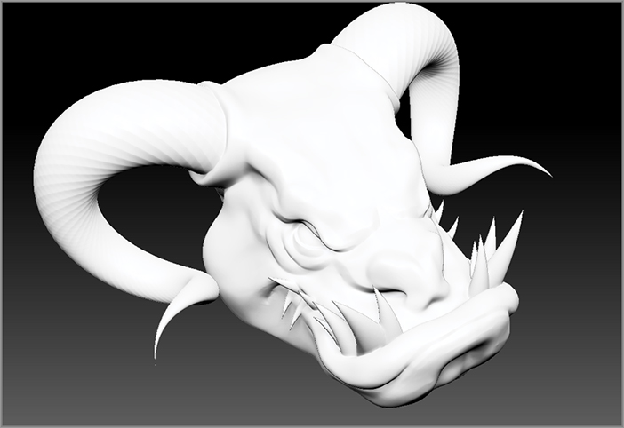
Figure 4-2 : Hold Ctrl+Shift and drag the green rectangle over the area you want to select. Let go, and the unselected portion is hidden.
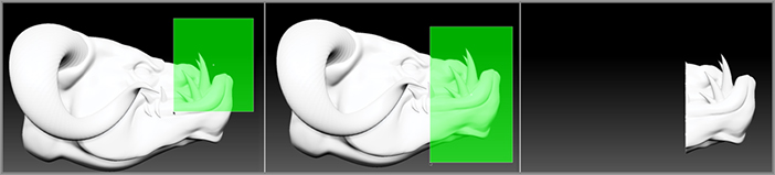
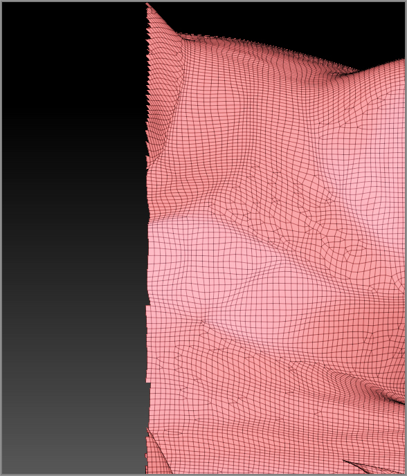
Figure 4-3 : The jagged edge along the border of the selection is caused by the edges of the polygons that remain visible.
The green rectangle indicates the selection area. Place this over the area that you want to select (Figure 4-2, center).
The parts of the mesh that are outside the selection area disappear (Figure 4-2, right). Don’t worry; they have not been deleted; they’ve just been hidden. The jagged edge of the visible part is caused by the fact that the polygons along the edge are still visible. This is easy to see when you zoom in on the edge and turn on the PolyF button to see the wireframe (see Figure 4-3).
Figure 4-4 : The back sides of the faces are invisible by default. Turn on the Double button in the Display subpalette of the Tool palette to see the opposite side.
ZBrush hides the reverse side of polygon faces to make performance more efficient. Double is usually off by default. It’s a good idea to turn Double on so that you can see both sides of the faces while you’re working. If Double is off, you may not see parts of the model that are selected, and this can lead to mistakes down the road.
- Selection brushes work with symmetry, so if symmetry is active, then the selection will be mirrored across the axis of symmetry.
- To switch to the SelectLasso brush, hold Ctrl+Shift and click the brush library on the left shelf. You’ll see an abbreviated version of the library containing all the brushes that are mapped to the Ctrl+Shift keys, as shown in the following image.
- The SelectLasso brush lets you make freeform selections, so you simply draw out a green area. Anything within the area is considered selected. This is useful for selecting areas that are a bit tough to select with just the rectangle.
- You can change the stroke type for the current select brush by holding Ctrl+Shift and clicking the Stroke Type library icon on the left shelf. You can change the stroke type to Circle, Curve, Rectangle, or Lasso (yes, this means that it’s possible to assign the Lasso stroke type to the SelectRect brush and vice-versa. Try not to do that because you’ll get confused very quickly). If you want to invert the selection so that everything inside the selected area is hidden, hold Ctrl+Shift and then hold the Alt key. The selection area now turns red, indicating that the selection will be hidden.
- You can toggle between selections by Ctrl+Shift-clicking on the visible part of the mesh. This inverts the visibility of the mesh so that the hidden part is revealed and the revealed part is now hidden.
- You can hide a single edge loop of the mesh by choosing the SelectLasso brush and Ctrl+Shift-clicking on a polygon edge, as shown in the image. This is easy to do by mistake. If rows of polygons disappear when you Ctrl+Shift-click on the model, just undo (Ctrl+Z) and try again. This takes a little practice to get the hang of it.
Masking Selections
How are selection brushes useful? You’ll find going forward that there are a lot of ways in which the selection brushes can be used to edit a model, especially as the model becomes more complex. One way I find the brushes useful is to mask parts of the surface quickly.
In this example you’ll see how the selection brush with the Circle stroke type can be used to create a mask for the eye area.
Figure 4-5 : Choose the Circle stroke type for the SelectRect brush. Activate the Square and Center options.
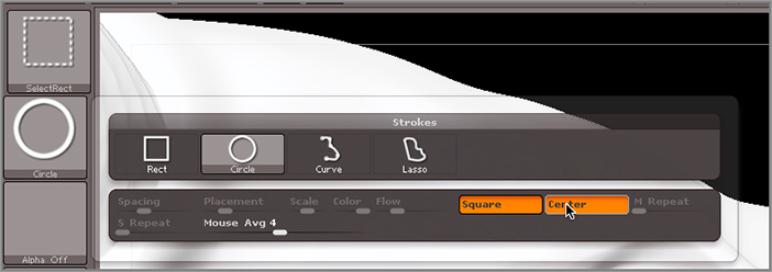
Why would you want to switch to a circle and then turn on the Square button? That sounds like crazy talk. Well, the Square button in the stroke type library does not actually make a square. This just means that the stroke of the brush will have the same length and height. When this option is applied to the Rectangular stroke type, the result is a selection that is a perfect square. When the Square option is activated for the Circle stroke type, the result is a selection that is a perfect circle.
The Center option means that the stroke will start from the center of the brush tip as opposed to the corner. The Square and Center options can be used independently or together. I like to have them both on when I use the Circle stroke type.
This is why it is important to make sure that the Double option in the Display palette is activated so that when you rotate the view after making the selection, you can see any the other polygons that may have been inadvertently selected.
Figure 4-6 : Use the selection brush to select a perfect circle around the dragon’s eye. Rotate the view to see if other parts were accidentally selected.
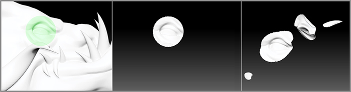
Figure 4-7 : Choose the SelectLasso brush and hold Ctrl+Shift+Alt to create a red selection area over the parts you want to hide (left image). Release the brush to hide these parts (right image).
Yes, it seems a little complicated the first few times you do this. In reality, with a little practice, it actually becomes second nature.
Figure 4-8 : After masking the selected area, Ctrl+Shift-click the canvas to reveal the surface (left image), Ctrl+click a blank part of the canvas to invert the mask (center image), and then Ctrl+click the surface to blur the mask (right image).
Now you can use the sculpting tools to work on just the eyes.
Every ZBrush artist uses selection and masking in their own way. This particular method is mostly designed to show you how selection and masking can be used together, but you may find a more efficient workflow as you become more experienced. But what happens when you go to all this trouble to make a mask, then you clear the mask, and then later on decide that you want to remask the same area? Do you have to go through all these steps again? Luckily no, you don’t. There is a way to save your selections for future masking and other tasks using polygroups.
Polygroups
Figure 4-9 : The polygons of a mesh have been arranged into polygroups indicated by the colored regions.
The polygons of a mesh can be organized into groups known as polygroups. This is useful when you need to isolate a particular part of a surface area over and over again. Rather than creating the same mask every time you need to work on one part of your mesh, which can be very tricky on complex surfaces, you can create a polygroup, which is saved with the mesh. The grouped area of the mesh can be isolated for masking and other operations as often as you like for as long as you keep the polygroup.
Polygroups are displayed as colors applied to the polygons. You can see these colors only when the PolyF button is enabled on the right shelf (hotkey = Shift+F). The colors of the polygons do not affect any colors painted on the surface. They just provide a visual indication of how the polygons of the mesh have been arranged into groups (see Figure 4-9).
- An individual polygon can’t be a member of more than one group at a time.
- Polygroups are saved as part of the mesh.
- You can rearrange the mesh into different polygroups as often as you like.
- You can create a polygroup when the mesh is at any subdivision level, but the results are more predictable when you create polygroups at the lowest subdivision.
- If you create a polygroup at a high subdivision level and then move the SDiv slider down to a lower level, the polygroups can get a little confused, which may alter the membership of the polygons in the polygroup.
Arranging a Face into Polygroups
In this example you’ll see how you can organize a face into polygroups and then how the polygroups can be useful when sculpting.
It’s highly unlikely that the selection you created was perfect on the first try. That’s OK; it rarely is. I always need to do a little cleanup after making an initial selection.
Figure 4-10 : Use the SelectLasso brush to select just the polygons of the face.
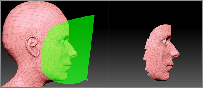
Figure 4-11 : The SelectLasso brush is used to hide stray polygons.
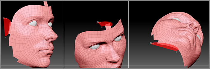
Figure 4-12 : Click the Group Visible button to place the visible polygons into a new polygroup.
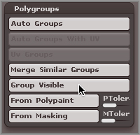
Figure 4-13 : The polygroups are indicated by different colors. These colors are visible only when the PolyF button on the right shelf is activated.
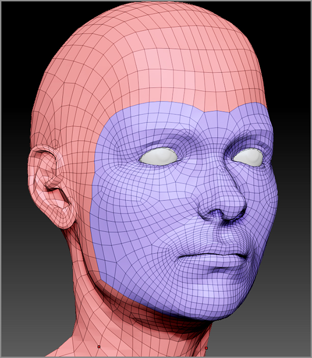
- The colors indicate the polygroups. ZBrush chooses the colors randomly. Sometimes ZBrush chooses colors that are very similar, making it hard to see the grouping. If you don’t like the color ZBrush chooses, just keep clicking the Group Visible button until you get a color you like.
- To hide everything outside the polygroup, Ctrl+Shift+click the center of a polygon within the group.
- To invert the visibility of the mesh, Ctrl+Shift+click again the center of one of the polygons within the polygroup.
- After inverting the visibility of a polygroup, when you Ctrl+Shift+click a polygon within a polygroup, that polygroup will become hidden.
- If you click a vertex shared by polygons in two or three adjacent polygroups, everything outside those polygroups will be hidden.
- If for some reason the polygroup is not created the way you want, you can press Ctrl+Z to undo and try again.
- You can convert a masked area into a polygroup by clicking the From Masking button in the Polygroup subpalette of the Tool palette.
- Polygroups exist regardless of whether the PolyF button is on or off. If PolyF is off (and the wireframe is not visible), the polygroups will still function the same way; you just can’t see them.
Creating a Polygroup for the Eyelids
Now let’s create a polygroup for the eyelids. Creating polygroups ahead of time for areas you frequently need to isolate is a common and useful ZBrush technique. This is going to be a bit of a challenge since the eyelids are very close together, but this process will teach you a few tricks that can help you out of a jam with your own models.
Figure 4-14 : Turn on the Solo button to hide the eyes.
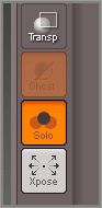
Figure 4-15 : Select the polygons around the eyes.
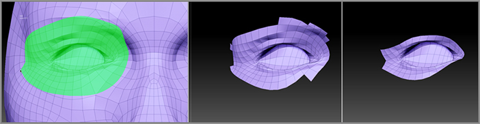
Figure 4-16 : Create a polygroup by isolating the polygons of the upper eyelid.
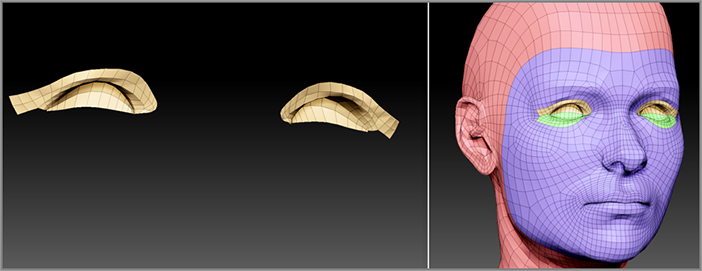
Figure 4-17 : The upper eyelid is easy to mask thanks to polygroups.

Using Morph Target to Create Polygroups
How do you create a polygroup for a truly tricky area, for example, the lips on this head? This is a challenge because the mouth is closed and the polygons of the lips overlap, making it very difficult to select with the SelectLasso brush. To get around this you can store a morph target.
A morph target stores the position of each vertex in the mesh in memory; it’s like the ultimate backup plan. As long as you have a morph target stored, you can always go back to the original shape of the surface even if you’ve made a million changes. Morph targets do not store the polygroup info, which is good because it means you can smooth out an area, create a polygroup, and then use the morph target to jump back to the original shape. This is exactly what you’ll do to make a polygroup for the lower lip on this model.
Figure 4-18 : Click the StoreMT button to store a morph target (left image). Once a morph target is stored, the button is grayed out and the other options become available (right image).
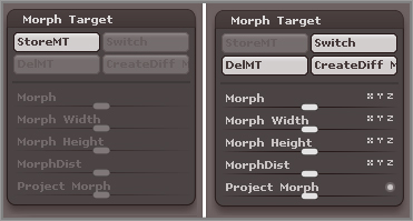
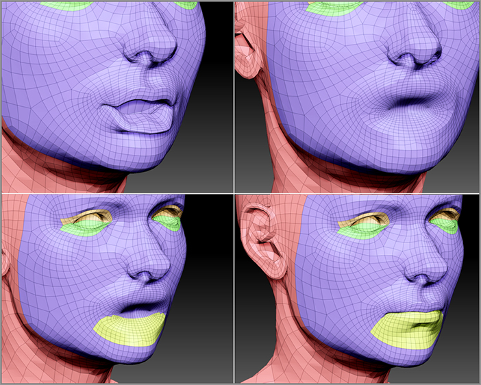
Figure 4-19 : After storing a morph target, pull the lower lip down (upper-left image). Use the Smooth brush to smooth the area for easier selection (upper right). Create a polygroup for the lower lip (lower left). Click the Switch button in the Morph Target subpalette to switch back to the original head (lower right).
- Morph targets are stored with the model when you save the project. As long as you don’t delete the morph target, it will still be saved when you reload the model at a later time.
- Store the morph target before you hide any part of the model.
- You can store only one morph target per model and only on the SDiv level where you created it.
- You can use the Morph brush in the sculpting brush library to paint parts of the model back into the stored state. This acts as an undo brush, which is extremely useful.
- 3D layers are a similar to morph targets but are much more advanced; these are discussed in Chapter 10, “Surface Noise, Layers, and The ZBrush Timeline.”
Polygroups and Dynamesh
You can create polygroups for parts of your surface while the model is in Dynamesh mode; however, once you “re-dynamesh” the surface, the polygroup disappears. This is because the surface is completely retopologized, meaning that the point order of the original surface is replaced by a new point order that obliterates the group information stored with the mesh. So how are polygroups useful when working in Dynamesh mode? Well, they offer a really great way to split the model into separate volumes and then stick them back together again. It’s actually quite amazing. Let’s take a look at how this works by returning to the dragon model.
Using the SliceCurve Brush to Create Polygroups
Let’s say you’re developing your dragon model, and you suddenly decide you don’t like the placement of the horns. Seems like it would take a lot of work to chop them off and stick them somewhere else on the head. In fact, it’s not a lot of work at all thanks to the SliceCurve brush. This brush lets you create polygroups by slicing through the mesh. The brush draws out a line, and anything on one side of the line becomes a new polygroup. It also divides the polygroups along the length of the line; this means that this brush is restricted to meshes that do not have multiple levels of subdivision.
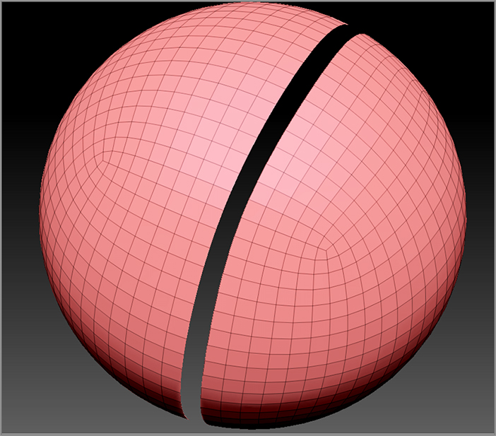
Figure 4-20 : Hold Ctrl+Shift and select the SliceCurve brush from the brush library
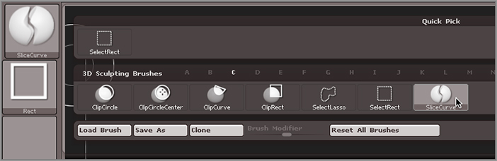
Figure 4-21 : Draw the SliceCurve between the head and the horn. Turn on the PolyF button to see the newly created polygroups.
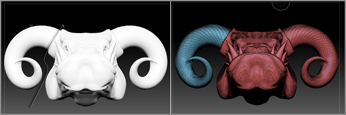
Figure 4-22 : Turn on the Groups button in the Dynamesh options of the Tool palette.
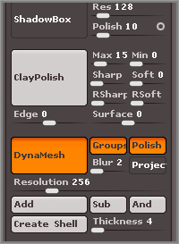
Figure 4-23 : When the head is re-dynameshed, the horn is separated from the head by a small gap.
Masking by Polygroups
At this point you’ve cut the horns off the head. Now it would be nice to move them away from the head easily. You can do this thanks to the Mask By Polygroups feature found in the Brush palette. By activating this feature, the brushes will affect only the polygons of the surface that share the same polygroup at the point of brush contact. Like many things in ZBrush, the verbal explanation sounds more complicated than what it actually means. Go through the following steps and it should become clearer.
Figure 4-24 : Set Mask By Polygroups to 100 in the Brush palette.
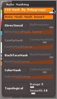
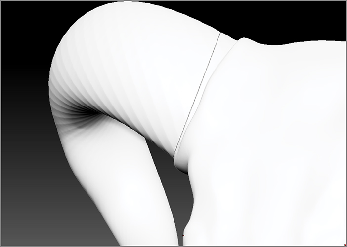
Figure 4-25 : Thanks to the Mask By Polygroup feature, the horns can be moved away from the mesh, rotated, repositioned, and fused back into the surface using Dynamesh. The sculpting brushes are used to make the mesh seamless.
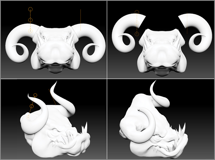
Notice that the end of the horn is closed off and there is no hole on the surface of the head; this is because Dynamesh created separate, closed volumes based on the polygrouping of the mesh.
It’s hard to overstate the amount of freedom this technique gives you. Performing a similar action in a traditional polygon modeling software package would take hours of work. In this case it’s like you’re lopping of a lump of clay, slapping it back on in another position, and smoothing it with your fingers. You can easily chop off a character’s head or arm and replace it with a different version as many times as you want.
Working with Subtools
Up to now you’ve done an awful lot with just a single mesh, but ZBrush does not limit you to single surfaces. You can actually build multisurface objects using subtools. Each subtool is an independent surface that can have its own levels of subdivision, its own polygroup arrangement, coloring, and so on. Furthermore, when you sculpt on one subtool, none of the other subtools are affected so that the other subtools are protected from accidental changes.
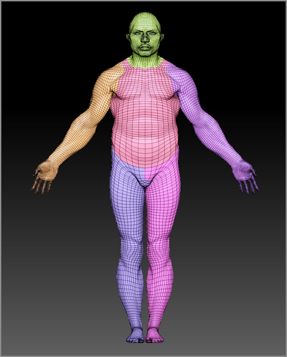
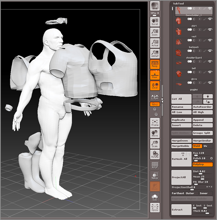
As you may recall from Chapter 2, a 3D mesh in ZBrush is also known as a 3D tool. This is because ZBrush considers tools to be anything that makes a mark on the canvas itself. For example, a 3D dragon tool can be used to paint copies of 3D dragons on the canvas. The term subtool is used to describe a 3D tool that has been parented to an initial 3D tool. There’s no technical difference between the types of meshes that become subtools and the tools themselves. You can add hundreds of subtools to your initial mesh, making your sculptures as complex as you’d like. The DemoSoldier example tool that comes with ZBrush is an example of a model that is made up of many subtools. To load DemoSoldier, open the Tool section of Light Box and click the DemoSoldier.ZTL file (see Figure 4-26).
Figure 4-26 : The DemoSoldier tool is made up of many subtools.
The relationship between tools and subtools is extremely simple. It is not meant to be a complex hierarchy like you might find in other 3D packages; a subtool is a 3D tool that is chosen and appended to a main tool, and that’s pretty much all there is to it. Using the SubTool interface in the Tool palette, you can rearrange the order of subtools, control their visibility, and add, delete, and even merge subtools together into a single tool. If you’ve used Adobe Photoshop, you may find that the concept of the SubTool interface is reminiscent of Photoshop’s Layers palette.
The SubTool Subpalette
The SubTool subpalette lists all the subtools associated with the main tool. To work with a subtool, it must be active. An active subtool is indicated by the coloring around the boxes listed in the SubTool subpalette; in the default color scheme, the active subtool is indicated by a dark outline. Other color scheme presets, such as the one used in this book, use a light-colored highlight to indicate the active subtool.
Only one subtool can be active at a time. To make a subtool active, you need to click its box in the SubTool subpalette or hold the Alt key while clicking on part of the object on the canvas.
On the canvas, the inactive subtools will be shaded in a slightly darker color than active subtools. If Transparency is enabled on the right shelf, all the subtools except the active subtool will appear transparent. The Ghost button changes the look of the transparent objects on the canvas.
On the right shelf, you can click the Solo button to temporarily hide all of the subtools except the active one. As you click different subtools in the SubTool subpalette, you’ll see the visibility of the current subtool on the canvas change as well.
- The subtools are listed in the SubTool subpalette as a vertical stack. Each subtool has its own box with a preview icon, its name, and a number of other buttons.
- Hold your mouse over the subtool’s box to reveal a pop-up window with information about the subtool, such as the number of polygons and points in the subtool at its current subdivision level.
- To the left of the stack of subtools is a scroll bar that becomes active when the list of subtools become too long to display in the SubTool subpalette.
- On the right side of the box for each subtool is an eyeball icon. This toggles the visibility of the subtool on the canvas. Click the eyeball icon of an inactive subtool to turn it off.
- The currently active subtool will remain visible regardless of whether or not the eyeball icon is on.
- To turn off the visibility of all the subtools except the currently active subtool, click the eyeball icon of the currently active subtool so that it turns off. This can also be achieved by clicking the Solo button on the right shelf.
- To turn on the visibility of all of the subtools at once, click the eyeball icon for the currently active subtool so that it turns on.
- To turn on the visibility of all of the subtools at once, click the eyeball icon for the currently active subtool so that it turns on.
- To switch from one subtool to another, select the subtool’s box in the SubTool subpalette.
- You can filter the display of the subtools in the List All pop-up box by typing the first letter of the subtool you are looking for. So, for example, if you want to quickly switch to a subtool named Goggles, just type G. If no other subtool start with g, the Goggles subtool will automatically become selected in the subtool stack. If more than one subtool starts with g, you’ll see all the subtools that start with g in the List All pop-up. Other subtools will be grayed out. Type the second letter of the subtool to switch to that subtool. For example, type G and then O to switch to the Goggles subtool while the List All pop-up is open.
- Next to the List All button are four arrow buttons. The top two arrow buttons can be used to move up or down through the list of subtools in the stack. The bottom two arrows change the position of the active subtool in the stack. The bent-upward arrow moves the subtool up one position in the stack, and the bent-downward arrow moves the active subtool down one position in the stack.
- The Duplicate button makes a copy of the active subtool and adds it to the stack of subtools.
- The Append button adds a tool selected from the tools available in the tool fly-out inventory to the bottom of the subtool stack; the Insert button does the same thing, but the appended subtool is placed just below the active subtool in the subtool stack.
- The Delete button deletes the currently active subtool. When you click this button, a warning message appears letting you know that deleting a subtool is not undoable.
- The Split Hidden button splits a tool into subtools based on which parts of the mesh have been hidden.
- The Grp Split button separates a tool into subtools based on how the mesh has been arranged into polygroups.
Sculpting a Hair Mesh
ZBrush’s subtool workflow is very flexible. You can append a raw lump of digital clay to an existing tool and sculpt it into shape, or you can append a fully sculpted object. In this example, you’ll append a PolySphere and use it as a starting point for a simple hairdo.
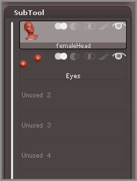
This project has the same female head you got to know earlier in the chapter. It actually already has a simple subtool arrangement. The head is one tool and the eyes are a subtool.
Figure 4-27 : The SubTool subpalette shows that the femaleHead and Eyes are separate subtools.
Now to create some hair you’ll append a PolySphere as a third subtool. Before you can do this you must load the PolySphere into the current ZBrush session.
When you load the PolySphere tool by double-clicking it, the female head disappears and is replaced by the PolySphere. Don’t panic; all that has happened is that you’ve switched the tool you are currently working on. Think of it as swapping tools on the virtual sculpting stand.
Figure 4-28 : Select the PolySphere.ZTL file from the Tool section of Light Box.
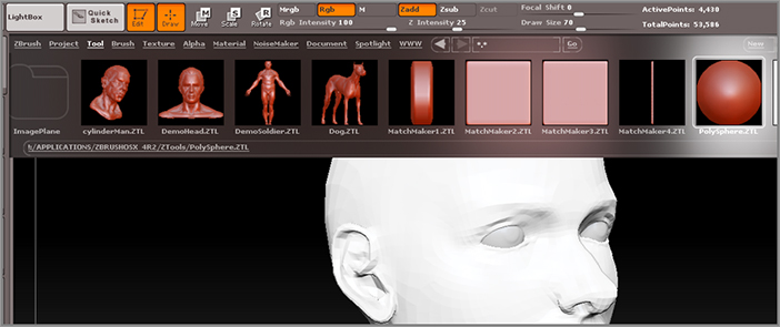
Figure 4-29 : The femaleHead tool in the tool library has a number 2 in the corner indicating the number of subtools in the model.
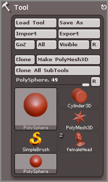
Figure 4-30 : Click the Append button to open the pop-up tool library; then select the PolySphere to add it to the femaleHead.
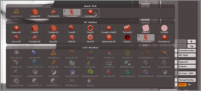
Figure 4-31 : Rename the PolySphere as Hair.
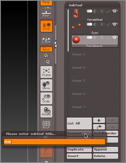
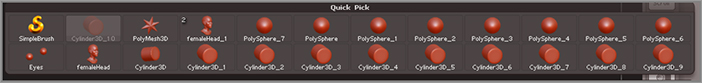
Figure 4-32 : Move the Hair subtool to the back of the head.
At this point you’re set up to start sculpting some hair. This usually takes practice, but you can use many of the techniques you learned in previous sections. Using Dynamesh makes hair sculpting much easier and faster than in previous versions of ZBrush. Of course, you can create realistic strands of hair using FiberMesh, but there may be situations in which you want to sculpt hair from a single polygon mesh. For example, let’s say you want to sculpt something that looks like a statue carved in stone. Creating realistic hair with FiberMesh is covered in Chapter 9; for this example we’ll keep it simple and create some “statue-esque” hair using Dynamesh.
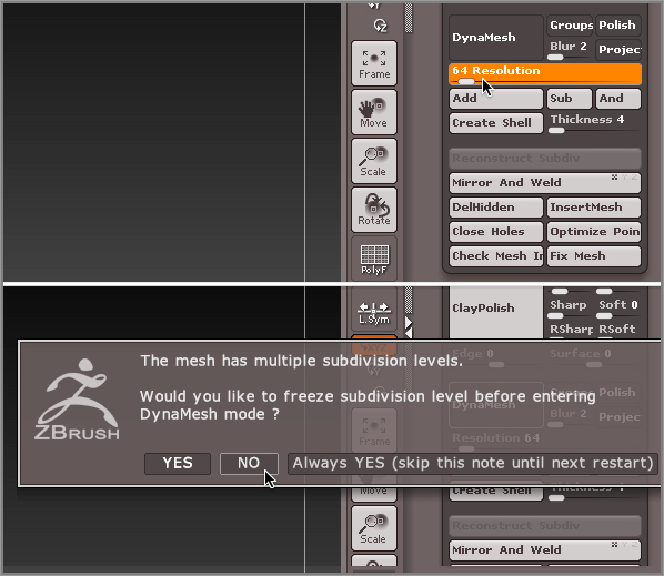
Figure 4-33 : Set the Dynamesh Resolution to 64 (top image). Click the Dynamesh button and then choose No when the warning message appears.
Before you start, though, you should save the project.
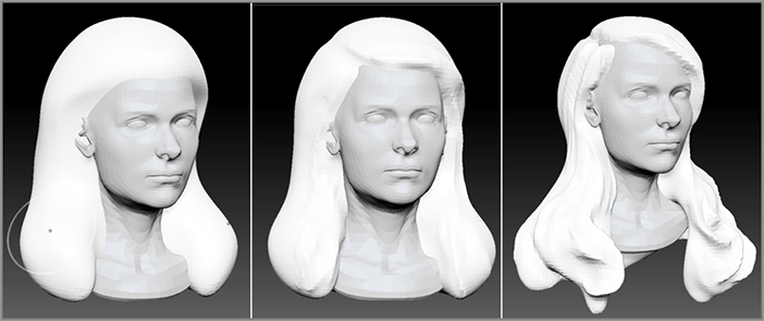
Figure 4-34 shows some of the stages I went through during the hair development. Note that at the end the hair is low resolution and not very detailed. I used only the Move and DamStandard brushes to create the basic shape.
Figure 4-34 : The hair is sculpted in Dynamesh mode. The resolution is increased only when more detail is needed.
- Have a reference close by (unless you’re a beauty school graduate). Some artists who have spent most of their time reading sci-fi and horror novels may suddenly realize what they’ve been missing by not leafing through glossy glamour magazines! (It gets even worse when you start sculpting clothing, and you realize you don’t know anything about fashion.) That’s OK; the Internet can come to the rescue. Do an Internet search for hair styles and find a style that you like; then use it for reference.
- Use the Move tool to block out the basic shape. As long as Dynamesh is active, just Ctrl+drag on the canvas whenever the polygons appear stretched.
- Clay Tubes, Clay Build-up, DamStandard, and the Rake brush are all very helpful for defining hair.
- Avoid focusing too much on one part; instead, work the entire surface over.
- If things get too blobby, use the Trim Dynamic or hPolish brush to define the forms with flat planes.
- Don’t worry about detail until you have the entire basic form blocked out.
- Toggle Persp on and off while you work so that you can see how perspective distortion affects the way the hair looks.
- The advantage of using a separate subtool for the hair is that if you don’t like what you’ve done, you can add a new PolySphere and start over, and you can add more hairstyles as different subtools. Test them out by simply toggling the visibility of each hair subtool off and on.
- It’s good to sculpt the hair at lower Dynamesh resolutions. You should only increase the resolution of Dynamesh when you feel you’ve done everything you can possibly do at the lower resolution. When you increase the resolution, do so by small increments. Go from 64 to 80, do as much work as you can, and then increase to 100 and then to 128 and so on. If you try to jump to a high resolution too early, you’ll find it difficult to maintain the control you want over the design, and it will look lumpy and unappealing.
SubTool Master and Transpose Master Plug-Ins
ZBrush has a number of free plug-ins that extend the capabilities of the program. Most plug-ins are free and are preinstalled. The most common plug-ins and instructions on how to install new plug-ins are found in the bonus chapter, “Zscripts and Plug-Ins,” which is included on the DVD that comes with this book.
The plug-ins (aka ZPlug-ins) are found in the ZPlug-in palette. If you don’t see a particular plug-in listed, then you’ll need to download it and install it. Plug-ins can be downloaded from Pixologic at this web address: www.pixologic.com/zbrush/downloadcenter/zplugins/.
SubTool Master adds a number of functions to help extend the capabilities of subtools. While many of these functions have been incorporated into the main interface in recent versions, there are still features that are very useful. In particular, the mirror function makes it easy to create a mirror copy of a subtool, which can either be added as a separate subtool or merged into the current subtool.
Transpose Master makes it possible to pose models that are made up of many subtools. It does this by making a clone of the current model. The clone is automatically set to the lowest SDiv level, and all the subtools are merged into a single object, allowing you to pose it easily with the Transpose handle. Once the model is posed, the plug-in allows you to automatically copy the pose back to the original model and all of its subtools. Transpose Master is demonstrated in Chapter 6, “Advanced ZSphere Techniques.”
ZSpheres
ZSpheres are unique ZBrush modeling tools unlike anything you’ll find in other 3D modeling programs. ZSpheres act as an armature for digital clay. Think of the wire skeleton a sculptor uses as the underlying structure for a sculpture. The wire armature is built and posed and then the sculptor adds clay to the armature to create the final figure. The armature acts as a support for the clay, but it can also be used to establish the initial pose.
ZSpheres are special spheres that can be connected into a network. The network of ZSpheres is then converted to a polygon mesh known as an adaptive skin. It is similar to a sculptor’s armature except that instead of adding clay to the armature, you convert the ZSphere armature directly into a sculptable mesh.
The polygon mesh that results from the skinning process is placed as a copy in the Tool palette. The new mesh is just like any other 3D tool and can then be sculpted using the sculpting brushes.
You can form anything you want out of ZSpheres, but they are particularly useful for things such as figures, trees, and creatures. Because a copy is made, you’re left with both a mesh and the original ZSphere armature, which can be reused as the basis for similar meshes in future projects. Let’s take a look at how to use ZSpheres.
ZSphere Basics
In this section, you’ll learn how to create and manipulate a basic ZSphere armature. Follow these steps to get started:
Figure 4-35 : The ZSphere tool in the Tool palette inventory
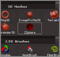
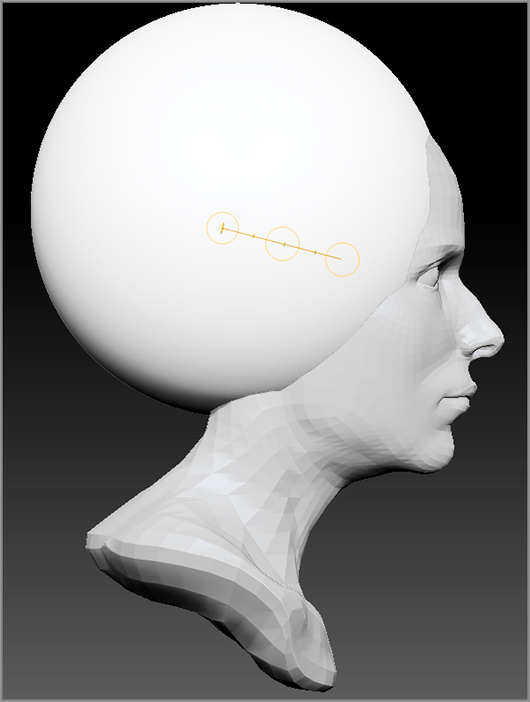
Figure 4-36 : As you hold the brush tip over the ZSphere, a line appears from the center of the ZSphere (left image). To add another ZSphere to the first, click and drag on the surface while the Draw button is active on the top shelf (right image).
You can add a new ZSphere to any existing ZSphere while the Draw button on the top shelf is active. The cursor will turn green to indicate the best place to add a new ZSphere. The position of one ZSphere relative to another affects the topology of the final mesh, making it more or less easy to sculpt. ZBrush gives you hints, such as the green color of the cursor, to help you decide where to add new ZSpheres. In some cases you can bend the rules and place a ZSphere when the cursor is not green; it depends on what your final objective for the mesh is going to be. In general, when learning how to use ZSpheres, try to follow the hints suggested by the color changes.
You currently have a very simple ZSphere chain on the canvas. You’ve also established a simple hierarchy: The triangular icon indicates the relationship. The wide end of the triangle is at the center of the parent ZSphere, and the pointed end is at the center of the child ZSphere. The gray spheres in between are the connecting ZSpheres. These connecting ZSpheres act as a bridge. They can’t be directly manipulated unless you convert them to standard ZSpheres.
Figure 4-37 : Click a connecting ZSphere while in Draw mode to add a ZSphere between the two original ZSpheres. Drag on the ZSphere while in Move mode to change its position.
The Rotate (hotkey = R) and Scale (hotkey = E) buttons work in a similar fashion. When you have the Rotate button activated, dragging on a ZSphere will cause it to pivot about its center, and dragging on the connecting sphere rotates all of the child ZSpheres. The Scale button allows you to scale individual ZSpheres by dragging on them or all of the child ZSpheres by dragging on the connecting ZSpheres.
- In Draw mode, drag on a ZSphere and then hold the Shift key to add a second ZSphere that matches the size of the first.
- Lower your draw size to more precisely select and manipulate individual ZSpheres.
- ZSpheres can be added to existing tools as subtools, so you can use them to create additional props such as clothing or equipment for characters.
- ZSpheres work with symmetry; you can turn on radial symmetry to quickly create elaborate designs such as trees or cephalopods.
Skin ZSpheres
Skinning is the process of converting a ZSphere armature into a polygon mesh that can then be sculpted. ZBrush has two skinning methods: adaptive and unified. Usually a ZSphere armature uses adaptive skinning.
Adaptive Skinning
Adaptive skinning creates a polygon mesh based on the ZSphere armature. Think of wrapping the armature with a membrane made up of polygons. When you convert a ZSphere armature into an adaptive skin, the skin itself is stored as a copy in the Tool palette, and you can then continue to sculpt. While you are working with the ZSphere armature, you can preview the adaptive skin very easily, which can help you make decisions about the position of ZSpheres while you work, up until you are ready to convert the armature into an adaptive skin.
When starting a ZSphere model, you’ll need to create a simple chain of at least three ZSpheres in order for the skinning process to work correctly. There is a simple workflow that ZBrush artists use when starting a typical ZSphere armature:
You’re going to add two ZSpheres, one on each side of the original ZSphere, to start the ZSphere armature. You can use this trick to help precisely position the two child ZSpheres.
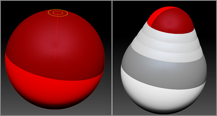
Figure 4-38 : The basic approach to starting a ZSphere model involves creating a simple chain of three ZSpheres.
If you start with fewer than three ZSpheres, you’ll end up with a hole at one end of the skin that will look strange and produce unpredictable results.
You can actually sculpt the preview mesh using the sculpting brushes while you work, but you should avoid doing this. If you sculpt the mesh while in Preview mode and then make a change to the armature by adding additional ZSpheres, your changes will be lost, and in some cases it can really mess up the model.
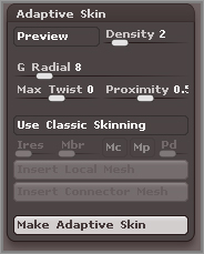
The best approach is to create your ZSphere armature, pose it, and preview often while you work. When you have a satisfactory ZSphere chain, you can then click the Make Adaptive Skin button in the Tool palette (this button appears only when you’re working with ZSpheres; see Figure 4-39), and you’ll find that the mesh is placed in the Tool palette library. The prefix skin_ is added to the name of the mesh to distinguish it from the original ZSphere armature. Once you create the skin, you can append it to another tool as a subtool or draw it on the canvas and sculpt away.
Figure 4-39 : The Make Adaptive Skin button converts the armature into a mesh that you can sculpt.
Creating a Body for the Dragon Using ZSpheres
In this section, you’ll learn how to create a body for the dragon head model you sculpted in Chapter 3 using ZSpheres. Follow these steps to begin:
Figure 4-40 : Append the ZSphere to the dragon head model.
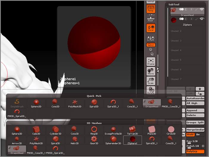
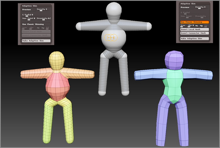
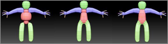
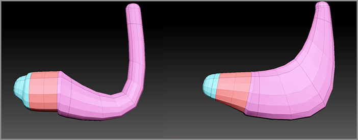
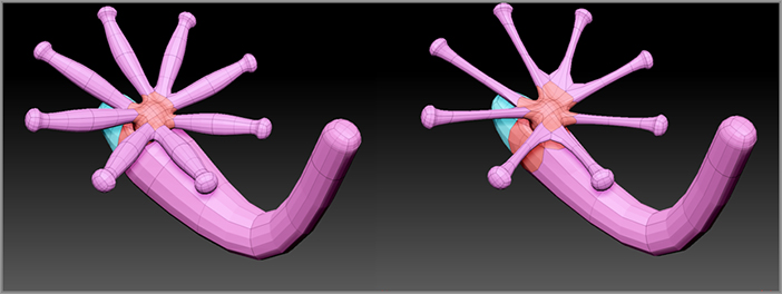
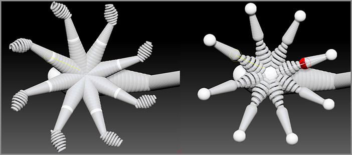
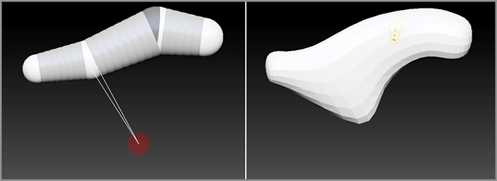
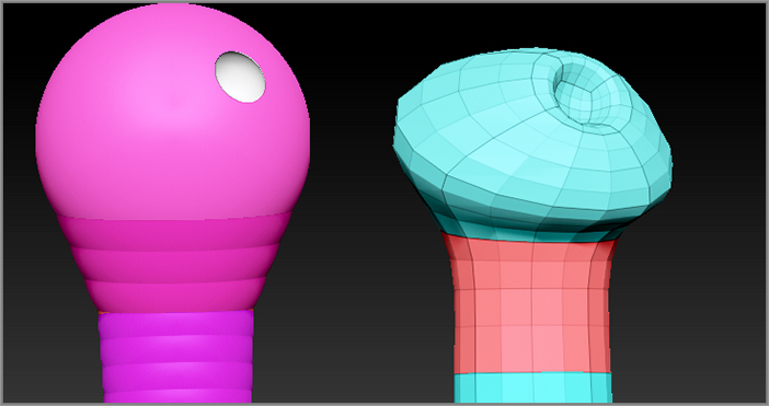
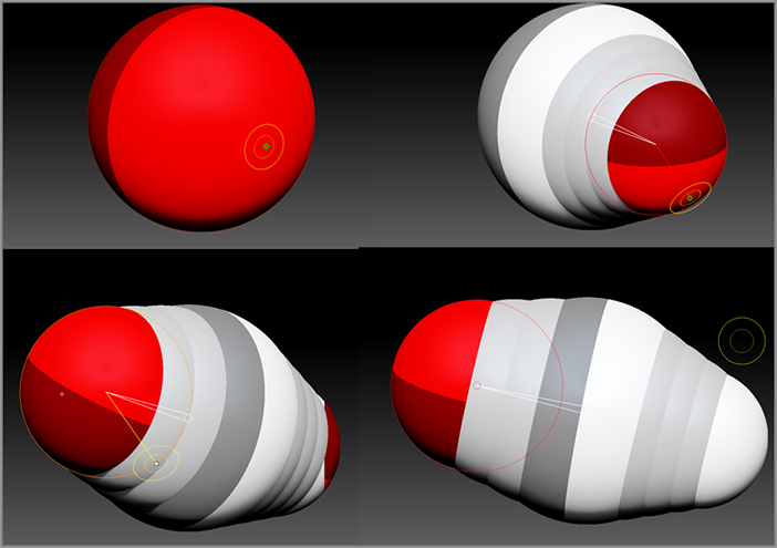
Figure 4-41 : Turn on Transparency so that the ZSphere is visible in the dragon’s head (left image). Move the ZSphere to the back of the head (center image). Add a ZSphere to the front and back of the initial root ZSphere (right image).
In the next section you’ll add legs and a tail.
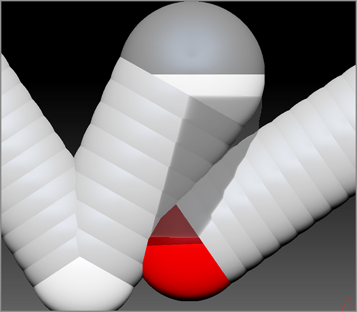
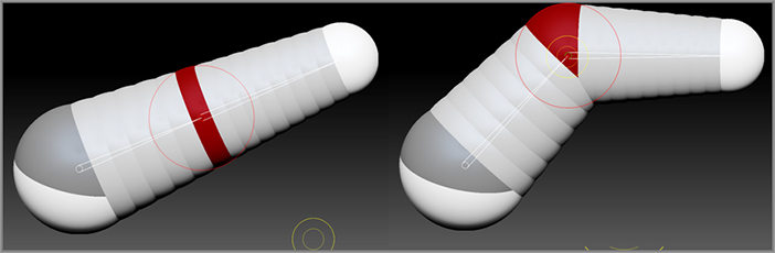
Figure 4-42 : Pull the rear ZSphere back, and add three ZSpheres by clicking the connecting ZSpheres. Scale the new ZSpheres up, and use Move to position them to form the body.

Adding ZSphere Legs and a Tail
In this section, you’ll add legs, complete with feet and toes, and a tail. The emphasis will be on keeping things simple so that it’s easier to sculpt the surface once it’s converted to a mesh.
Figure 4-43 : Add legs to the front of the Dragon (upper left). Press the A hotkey to check for errors in the mesh (upper right). Pull the legs downward to extend them (lower left). Insert knees in the model of the leg (lower right).
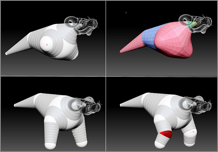
Figure 4-44 : Add a ZSphere to the end of the front legs to create feet.
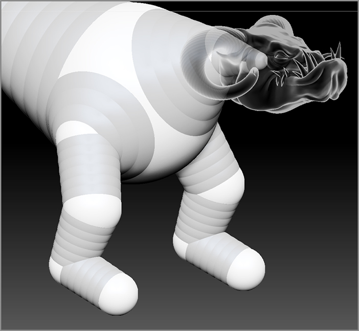
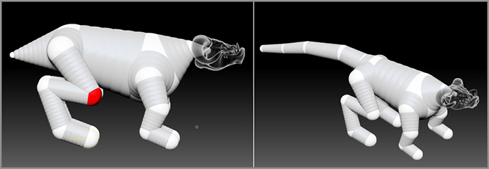
Figure 4-45 : Use ZSpheres to add back legs (left image) and a tail (right image).
You can add toes using the same techniques; however, there’s a trick you can use that will make toes easier. This trick also works well for human fingers.
This idea behind this technique for adding toes is that by first creating a knuckle ZSphere and then creating a finger ZSphere, you avoid the conical shape that would be created by simply adding the finger without the knuckle.
Figure 4-46 : Add a knuckle to the foot (top left). Draw the toe and hold the Shift key as you draw to match the size of the knuckle; then pull this away from the foot (top right). Add a ZSphere in the finger to create a joint (bottom left). Press the A hotkey to preview the result (bottom right).
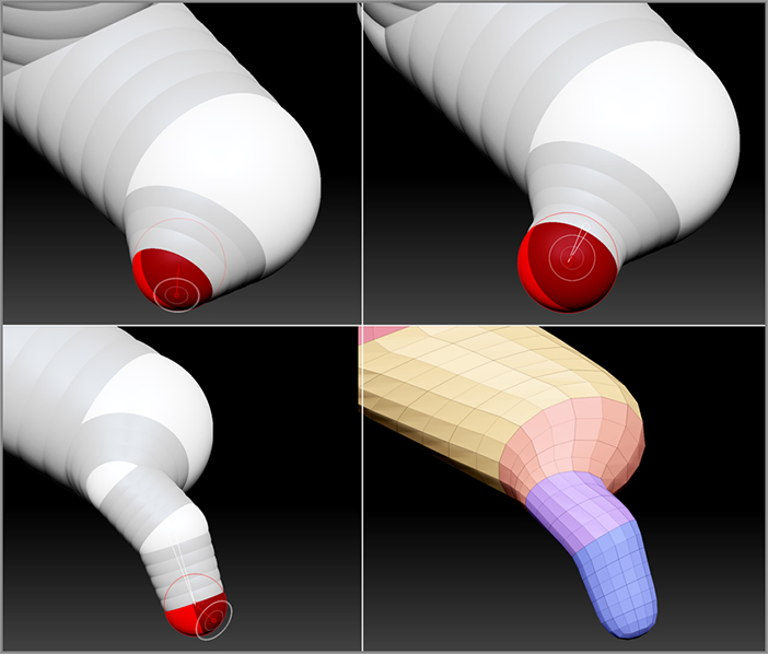
Figure 4-47 : Toes are added to the back feet, and the armature is adjusted to shape the dragon’s body.
Skinning the ZSphere Dragon Body
The basic ZSphere body created in the previous section is your armature. To make the ZSpheres into a sculptable surface, you’ll convert it to a mesh using adaptive skinning.
Figure 4-48 : Click the Make Adaptive Skin button in the Adaptive Skin subpalette of the Tool palette.
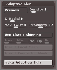
Figure 4-49 : Append the skin to the dragon as a subtool.

Now the dragon model has three subtools: the dragon_head, the ZSphere, and the skin_ZSphere1 surface. You can neaten things up a little by renaming the skin_Zsphere1 subtool and deleting the original ZSphere tool. You don’t have to delete the tool, and in some cases you may find that there’s a good reason to keep it around. In this case, you can delete it to keep the subtool stack simple and uncluttered. Deleting a subtool is not undoable, meaning that if you change your mind after deleting it, it’s too late to bring it back. For this reason I make it a habit to always save the project before deleting a subtool.
Figure 4-50 : Subdivide and sculpt the body using the sculpting brushes.
Merging the Head and Body
At this point you can merge the DragonHead and DragonBody subtools so that it will be easier to create a seamless transition between the head and the body. Merging subtools means that two subtools are collapsed into a single subtool. The geometry remains intact, but now the merged surfaces can be affected by the sculpting brushes as a single mesh.
It’s important to understand that you don’t have to merge subtools unless you want to; it’s ultimately an artistic choice. I have created many ZBrush models over the years that consist of dozens of subtools, and that’s perfectly fine. It is necessary to merge subtools if you want to create a single seamless surface using Dynamesh, which is why you’ll merge the head and the body in this section.
Figure 4-51 : Click the Merge Down button to merge the head with the body.
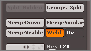
Figure 4-52 : A warning message lets you know that merging is not undoable.
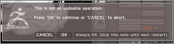
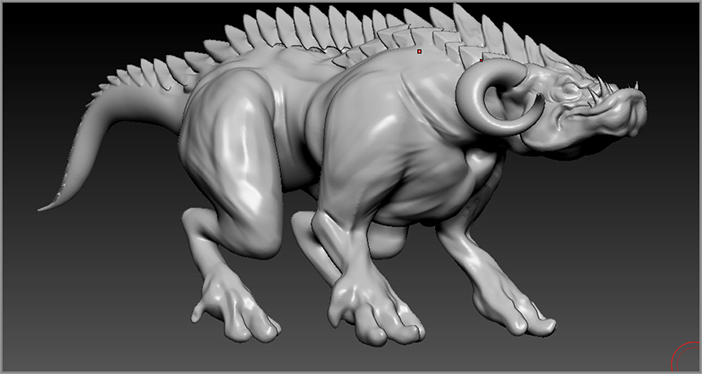
Figure 4-53 : After the dragon is merged, it is dynameshed and sculpted
- The Merge Down button merges the selected subtool with the subtool directly below it. If you need to merge two subtools that are not next to each other in the stack, use the arrow keys to move the subtools as needed.
- The Merge Similar button merges subtools that have the same polygon count and geometry. For example, if you have a separate subtool for each wheel on a car and the wheels are all duplicates of each other, you can use this button to automatically merge them all into a single subtool.
- The Merge Visible button creates a copy of the tool in the tool library in which all subtools that are currently visible are merged into a single tool. Note that when you use this button your current tool won’t look any different; you have to keep in mind that the merged version has been placed in the tool library.
- When subtools are merged, the polygrouping is maintained so you can continue to isolate parts of the mesh for masking.
- You can use Group Split to split a surface into multiple subtools based on the polygrouping of the mesh. Make sure that before you use this feature, the polygroups have all been organized in a logical fashion so that you don’t end up with a few hundred or so subtools.
- If you would like to merge two subtools while at the same time keeping their subdivision levels, make sure that both subtools have the same number of subdivisions and that both are set to their highest subdivision level before merging. This works most of the time, but always save your file before merging.
ZSketching with ZSpheres
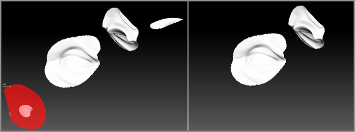
ZSketching involves painting ZSpheres on top of an existing ZSphere armature or mesh object. It’s an amazing process that feels just like adding strips of clay to a model. The ZSketch can then be skinned using unified skinning. The unified mesh creates a sculptable object made up of square and triangular polygons that evenly cover the surface. This is the same type of topology you get when using Dynamesh. This differs from an adaptive mesh introduced earlier in the chapter, which adapts the size and number of polygons based on the size of the ZSpheres (see Figure 4-54). Think of ZSketching as yet another tool in your arsenal that you can use to start a digital sculpture.
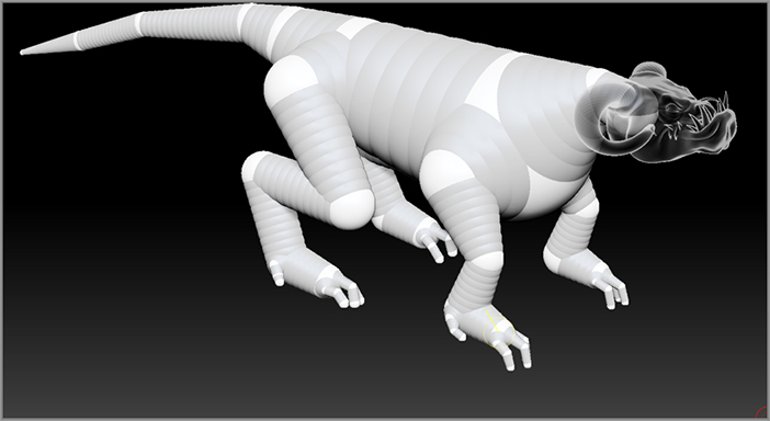
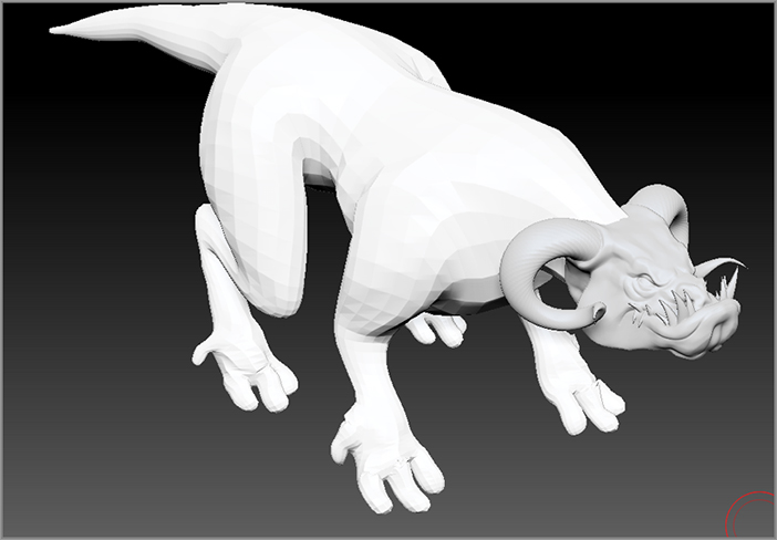
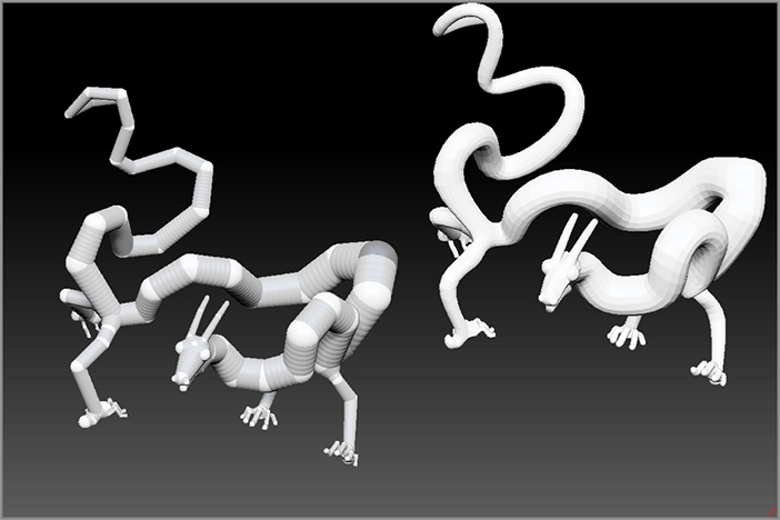
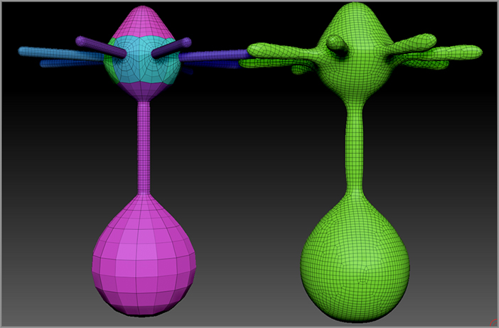
Figure 4-54 : A ZSphere armature has been converted to an adaptive skin in the left image. The same armature has been converted to a unified skin in the right image.
Creating a ZSketch
In this example, you’ll learn how to create another style of dragon head using ZSketching. ZSketching can be applied to an existing ZSphere armature, or you can simply start with a single ZSphere and then use the special ZSketch sculpting brush to create forms in empty space. Since this is the easiest way to ZSketch, you will use this method:
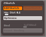
Figure 4-55 : The EditSketch button is enabled.
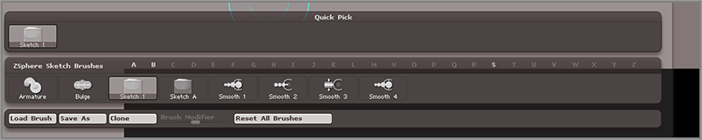
The sculpting brushes in the library switch to a subset of the sculpting brushes designed to work only when ZSketching (see Figure 4-56). These brushes can be divided into several groups:
Figure 4-56 : The ZSketch brushes
The ZSpheres you add with the ZSketch brush are unlike the ZSpheres you used to make the dragon armature. These ZSpheres can only be added using the special ZSketch brushes when ZSketch mode is on. You need to have at least one ZSphere on the canvas, and the sketch has to start on a ZSphere, but after the initial stroke you can continue to add more ZSpheres and build up the model by drawing on existing strokes.
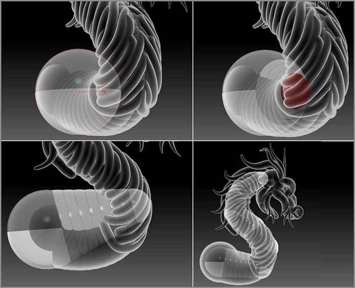
Figure 4-57 : New ZSpheres are sketched onto the initial ZSphere (top image). The ZSpheres are smoothed into the surface when you brush them with the Smooth brush (bottom image).
The Smooth 2 brush will push the end ZSketched ZSpheres into the armature but it will not change the radius of the ZSpheres.
The Smooth 3 brush will not change the radius of the ZSketched ZSpheres. It applies a global smoothing to the sketch, which can help straighten the line of the ZSketch.
The Smooth 4 brush scales the end ZSpheres down and embeds them deeper onto the other ZSpheres.
The typical method for adding ZSketched ZSpheres to an armature is to draw out a single line using the ZSketch ZSpheres on the armature and then smooth the newly added ZSpheres using whichever smoothing brushes you prefer. Do this each time you sketch on the armature to ensure that the model is neat and easy to use. Think of it as adding strips of clay to your model. Each time you add a strip, use a smoothing brush to push it into the rest of the models, just as if you used your thumbs to smooth out the strip of clay on a real model.
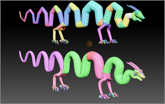
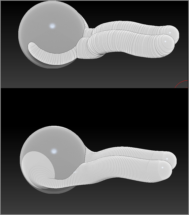
Figure 4-58 : The dragon’s neck is started by painting an S shape. The Smooth brush is used to refine the shape. In perspective view, you can see how two lines of ZSpheres overlap to form the neck.
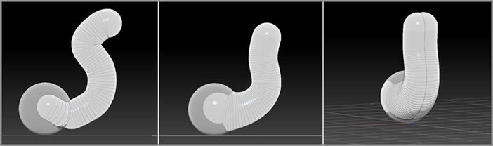
Figure 4-59 : Use Move and Scale modes to adjust the position and size of the ZSketch.
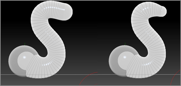
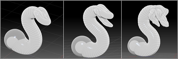
Figure 4-60 : A basic head is created at the end of the neck using the ZSketch brushes.
When you’re smoothing multiple lines of sketched ZSpheres, the smoothing brushes work on whichever sketched line of ZSpheres you touch with the smoothing brush first and then any lines sketched after that. For example, if you sketch three lines of ZSpheres on top of each other and then use the smoothing brush to straighten them, if you touch the third line first with the smoothing brush, only the third line will be smoothed. However, if you touch the second line first with the smoothing brush, both the second and third line will be smoothed. Touching the first line with the smoothing brush will smooth all three. This feature gives you precise control over how the smoothing is applied.
Absolute precision is not necessary when ZSketching. The process should feel natural and organic, which is why it’s called ZSketching. The best approach is to add a few lines at a time, slowly and deliberately, and then hold the Shift key while brushing to smooth the forms of the model. Be mindful, but not obsessive, of how you paint the ZSpheres on the armature because their position and size can affect the look of the unified skin.
Previewing the Unified Skin
Just as when you created the ZSphere armature, you can preview the mesh that the ZSketch will create by pressing the A hotkey. Remember that you don’t want to use the sculpting brushes on the ZSketch preview. Once you’re finished with the ZSketching, you will convert the ZSketch into a skinned copy, which you can then sculpt into a more refined shape. A number of settings in the Unified Skin subpalette toward the bottom of the Tool palette will determine how the unified skin looks and behaves (see Figure 4-61).
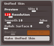
Figure 4-61 : The settings in the Unified Skin subpalette of the Tool palette
Typically, ZSketch ZSpheres are converted into a unified mesh, as opposed to an adaptive mesh. As mentioned earlier in the chapter, a unified mesh is made up entirely of quadrilaterals that are all the same size. You can increase the number of polygons in the mesh and reduce their size by increasing the resolution of the preview.
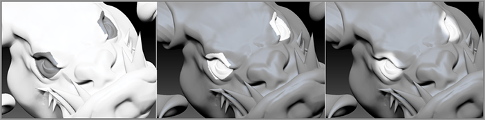
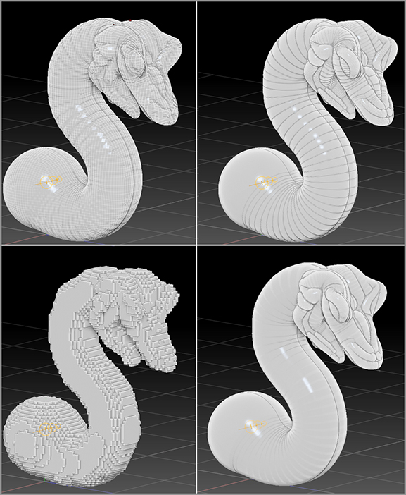
Figure 4-62 : The ZSketch dragon is previewed using various settings in the Unified Skin subpalette of the Tool palette.
The ideal resolution value for your particular ZSketch will vary depending on the ZSketch; usually it takes some experimentation to find the value that’s right for you. You try to get the lowest density mesh possible that still retains the level of detail that you want for the sculpt. Remember that eventually you’ll be working over the converted mesh with the sculpting brushes, so you may not need to have a very high resolution to get the basic shape of the ZSketch.
- SDiv subdivides the resulting mesh just as when you add subdivisions to a regular mesh object. The Preview button displays the mesh at the subdivision level specified by the SDiv slider.
- Smooth evens out the surface of the mesh. For an interesting look, try setting the resolution to 128 and the Smooth slider to 0. The mesh will look as though it is made of tiny cubes (see Figure 4-62, lower left).
- The Sdns slider will add ZSpheres in between every ZSphere that was sketched out. It will create a smoothing, in a way. For example, if you set it to 100, ZBrush will add 100 ZSpheres between the ZSpheres that were sketched out. The lower-right image in Figure 4-62 shows the unified mesh with a Resolution value of 400, Smooth value of 10, and Sdns value of 100.
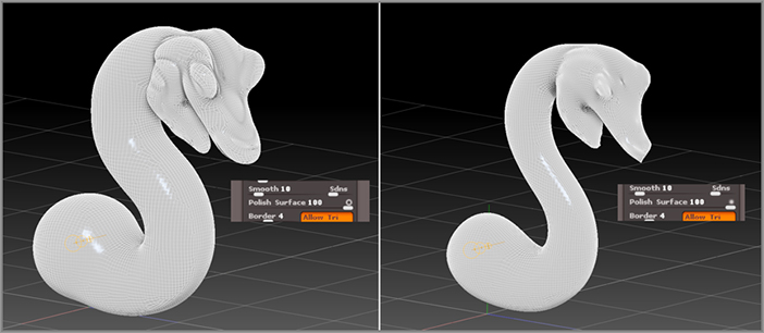
- The Polish Surface slider is another way to smooth the surface. There are two Polish modes you can use to polish the surface. To choose a mode, click the tiny circle to the right of the Polish slider. The open circle ensures that the polished mesh will maintain the original volume of the ZSketch. The closed circle allows the skin to be stretched; the original volume is ignored, as shown in the following image. Experiment with different combinations of values for the Smooth and Polish sliders and see how they affect the mesh preview.
- The Border slider is active only when Polish is above 0. Each line of ZSpheres you sketch on a surface generates a new polygroup. The Border slider inserts loops of polygons along the borders of existing polygroups. The number of loops is determined by the value of the Border slider. The result is similar to when you apply the Group Loops button in the Geometry palette to a regular mesh object. The Smooth slider has to be more than 0 in order for ZBrush to generate the loops. The following image shows how loops are inserted in the mesh when the resolution has been set to 128.

- The Allow Tri button lets ZBrush generate triangular polygons when needed. This can result in a smoother-looking mesh.
Adding Details
To create the face, use a small Draw Size value and scale up the view to zoom in on the head:
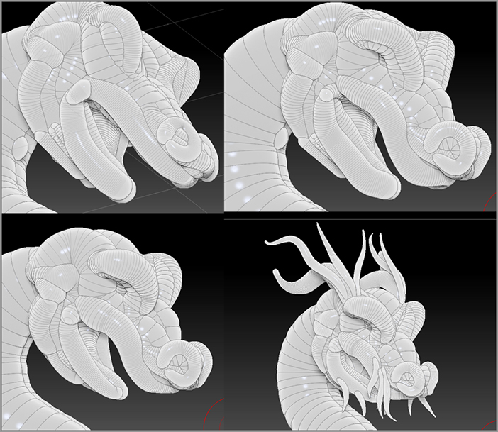
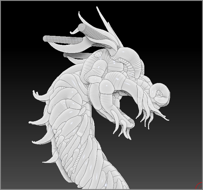
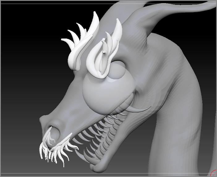
Figure 4-63 : The face is formed using a variety of ZSketch brushes.
- To reposition the ZSpheres you paint on the surface, you can use the Push Pull brush or switch to Move mode (hotkey = W) and drag the ZSpheres to place them wherever you like, even away from the ZSphere armature.
- To erase ZSpheres, switch to Draw mode (hotkey = Q) and use any of the ZSketch brushes while holding the Alt key.
- The Armature brush lets you easily paint the ZSpheres in any direction on the canvas as long as you start the stroke on the armature or on part of the exiting sketch.
- The Float, Flush, and Fuse brushes are found in the ZSketch section of Light Box under Brush. The following image shows where to find the extra ZSketch brushes in Light Box.
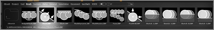
- Float pushes the sketch out along the original stroke direction, and holding the Alt key while using Float pushes the ZSketch in toward the model.
- Flush pushes and scales the ZSpheres along the viewing axis toward the back of the canvas. Hold the Alt key to push the ZSpheres in toward the model along the viewing axis.
- Flush Dynamic positions the ZSketch along the same plane based on the stroke path.
- Flush Resize uses the viewing angle to flatten the ZSketch line as well as scale the ZSketched ZSpheres.
- Fuse blends the ZSpheres together.
- In the Tool directory of Light Box are several examples of ZSketches created by other artists, such as the ZSketch_Bug, ZSketch_Critter, and ZSketch_Facial Anatomy tools. It’s a good idea to examine these sketches to pick up some useful techniques. The following image shows a facial muscle anatomy study created with ZSketching.
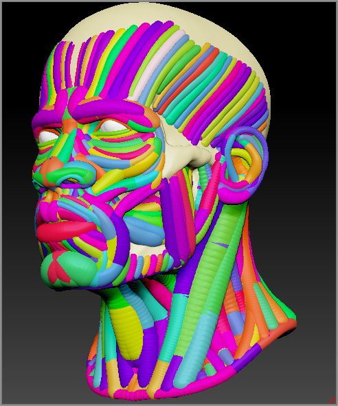
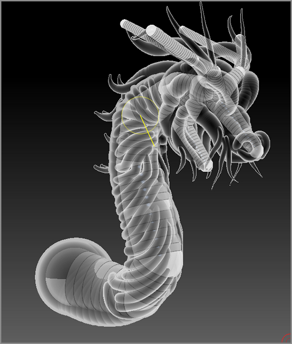
Figure 4-64 : Details are added to the rest of the neck.
Binding and Posing the ZSketch
You can repose the ZSketch while you are working on it using a ZSphere armature. In this exercise you’ll build a simple ZSphere skeleton for the ZSketch dragon and then use the skeleton to adjust the pose of the dragon.
Figure 4-65 : The ZSketch appears as a transparent mass over the original ZSphere.
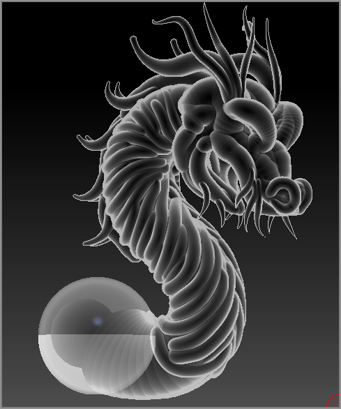
Figure 4-66 : ZSpheres are added to the initial ZSphere to form a simple armature for the neck.
Once you have created a basic ZSphere armature, you can bind the ZSketch to the armature and then move the ZSpheres around to adjust the pose of the ZSketch.
Figure 4-67 : ZSpheres are added for the jaw and horns.
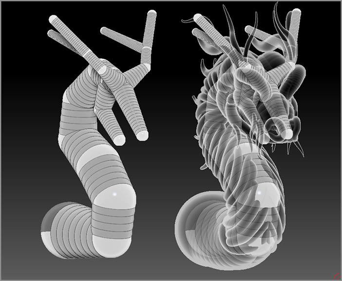
Figure 4-68 : The ZSketch is posed by moving the underlying ZSpheres.
In all likelihood you’ll need to spend some time cleaning up the model after posing. If you work slowly and methodically, you should be able to minimize the amount of touch-ups. The ZSketch is bound to the armature based on the distance between the ZSpheres and the ZSketch. You can turn off the Bind button, adjust the SoftBind slider, and even edit the position and scale of the ZSpheres in the armature and then click the Reset Binding button. Turn on Bind and continue posing.
Figure 4-69 : After posing, edit the ZSketch to fix any problems.
Creating a Unified Mesh
The whole point of ZSketching is to allow for an intuitive way to sketch out a design in three dimensions. ZSketching is perfect for when you want to experiment with ideas and concepts. Once you have the initial ZSketch created, you can convert it into a unified mesh, which allows for easy sculpting. From there you can continue to develop your idea.
Just as with standard ZSpheres, creating a unified mesh means making a copy of the ZSketch that is made up of polygons instead of ZSpheres. Before creating this copy, you’ll want to preview the unified mesh in order to fix any problems that may occur during the conversion process:
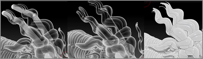
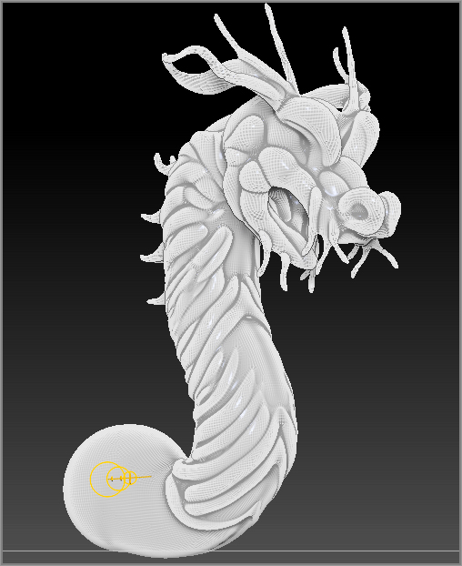
Figure 4-70 : Inspect the preview for holes and the quality of the mesh.
Sculpting the ZSketch
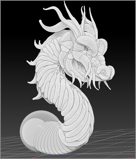
Once you have created the unified mesh, you can subdivide it just like any other 3D mesh and use your favorite sculpting brushes to shape it into a finished product. The unified mesh method of skinning creates a mesh in which all of the polygons are the same size and cover the mesh uniformly. This makes it easy to sculpt. However, if you want to use the geometry in an animation, you may need to retopologize the mesh so that it can easily be deformed in your animation software. Retopology is covered in Chapter 6, “Advanced ZSphere Techniques.” The sculpted dragon is shown in Figure 4-71.
Figure 4-71 : The unified mesh is subdivided and edited using the sculpting brushes.
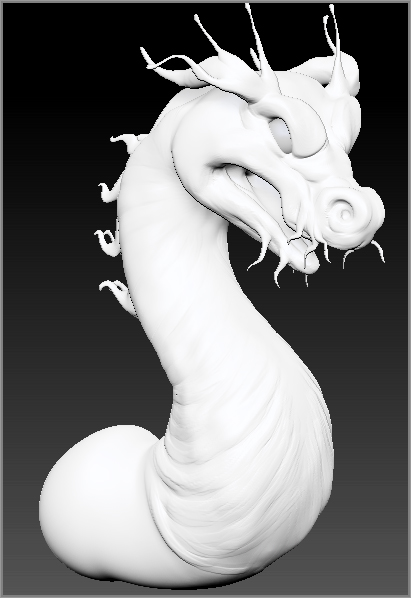
Save the final dragon as ZSketchDragon_v04.ZPR.
Summary
In this chapter you learned how to select parts of the mesh using the selection brushes. You learned how to organize the polygons of a surface into polygroups as well as techniques to use polygroups and masking together. You learned how to append subtools and work with the controls in the SubTool subpalette. You learned how to use the SliceBrush to cut apart a surface. ZSpheres were introduced as well as ZSketching techniques.