Chapter 9
FiberMesh, Materials, and Rendering
Once you have created a model in ZBrush, you will want to show it off to the world. Whether sharing your work online, presenting a model for approval from a director, or building up your portfolio, you’ll want to make your models look as good as they possibly can. To help you accomplish this, ZBrush offers several features that achieve spectacular images. FiberMesh can be used to create hair, plants, and other special effects. The new lighting system can be used to integrate models realistically into an image. To bring it all together, ZBrush offers a variety of materials and rendering options that create both stylized and realistic images without using an additional program.
This chapter gives an overview of how to create hair with FiberMesh and several examples of how to use the lighting and materials in ZBrush renders.
This chapter includes the following topics:
- FiberMesh
- Rendering basics
- Standard lighting
- Advanced lighting with LightCap
- Material basics
- Standard materials
- MatCap materials
- Applying materials
- BPR rendering techniques
- BPR render filters
FiberMesh
FiberMesh is the newest addition to the ZBrush toolset. ZBrush artists no longer must use other graphics programs, such as Photoshop, Autodesk® Maya®, or Autodesk® 3ds Max®, to add hair to characters, leaves to trees, or fur to beasts. FiberMesh generates fibers for these models and then sculpts the fibers into shape using a special set of sculpting brushes. The process involves two basic steps: creating a preview of the fibers and then accepting the settings that convert the fibers into strands, which then can be shaped, combed, and sculpted using the special hair brushes. In this example, you’ll work with the preview settings.
FiberMesh Preview Settings
The FiberMesh preview settings are located in a subpalette of the Tool palette and are available only when the current tool is a polygon mesh. If the current tool is a ZSphere or a Parametric 3D primitive, the Preview button in the FiberMesh subpalette will not be functional. Let’s use the preview settings to create a Mohawk hairstyle for the demon character introduced in Chapter 6.
Figure 9-1: Paint a mask on top of the head where you want to place the fibers.
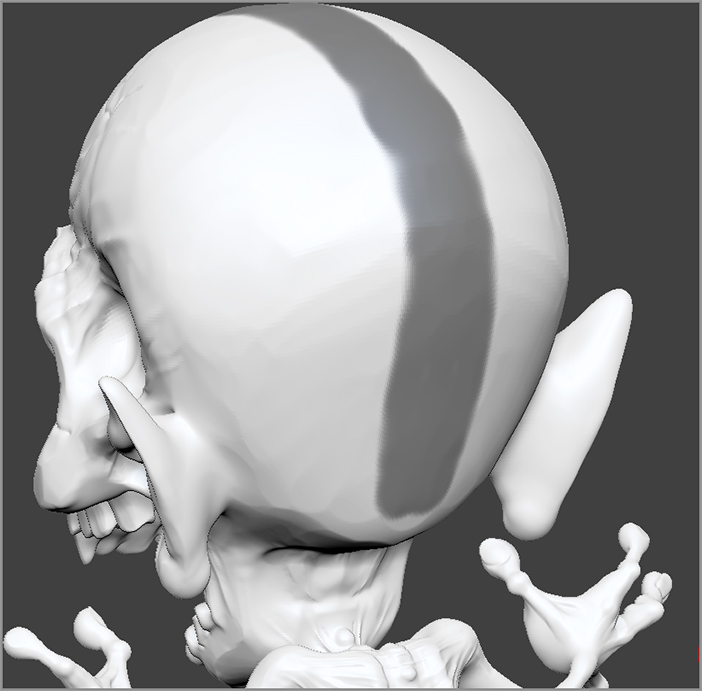
Figure 9-2: Turn on the Preview button in the FiberMesh subpalette in the Tool palette.
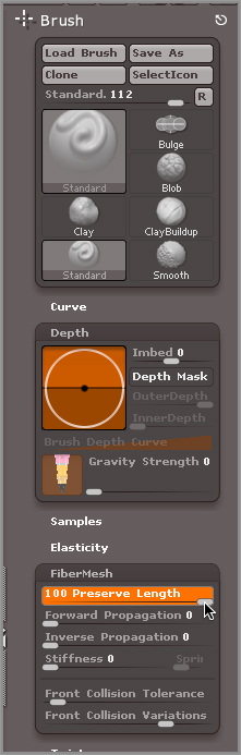
There are a lot of sliders in the FiberMesh subpalette: those in the upper portion affect the preview and hence the overall qualities of the fibers; those at the bottom control the fibers after they have been converted into a mesh. Figure 9-2 shows how the subpalette is divided. Each slider in the Preview portion controls the strength of the attribute. The small sliders on the right of the palette offer the ability to add a degree of randomness to each attribute. Let’s look at how this works.
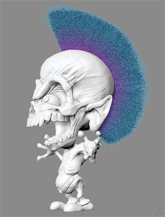
Figure 9-3: Set Gravity to 0 in the FiberMesh subpalette to make the hair stick straight out. The demon is a punk rocker now.
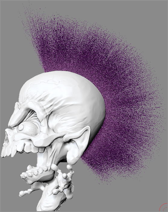
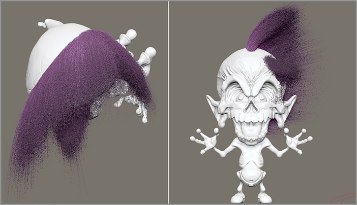
Figure 9-4: The results of the settings create a classic 1980s punk rock Mohawk.
Creating the Hair Mesh
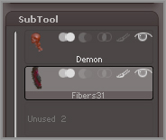
Once you have a hairstyle you like, you can accept the changes, which converts the hair into a subtool.
Figure 9-5: ZBrush asks if you want to activate Fast Preview mode when you click the Accept button.
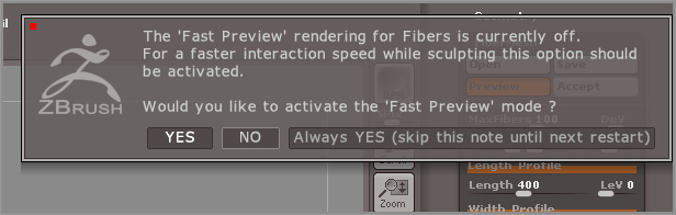
Figure 9-6: The hair is added as a new subtool.
Styling FiberMesh
Styling hair created with FiberMesh is easy, thanks to the powerful sculpting brushes that can be directly applied to the fibers. In this example you’ll use the brushes to create a hairstyle for a female character. For this character you’ll create long hair and style it so it looks somewhat realistic. The trick to styling long FiberMesh models is to start with short hair and then use the brushes to lengthen the hair as you work. This approach is much easier than shaping long fibers, which can be frustrating. It’s also important to use masking strategically as you work.
Figure 9-7: Paint a mask on the woman’s head, and then erase a line in the mask to create a part line.
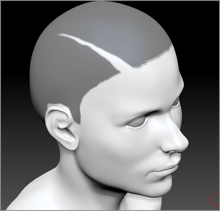
Figure 9-8: The settings create a short hairstyle on the female’s head.
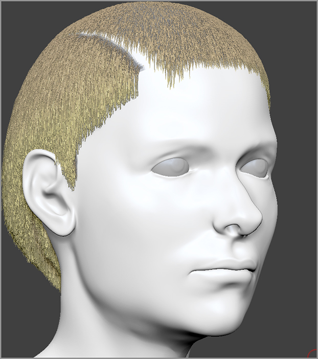
Figure 9-9: The short hair is styled using the GroomHairShort brush.
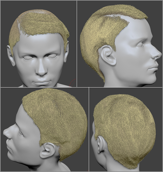
Figure 9-10: Set the Preserve Length slider in the Brush palette for the Smooth brush.
Lengthening the Hair
Now to add length you’ll switch to another brush, which allows you to pull out the hair. We’ll start by lengthening the hair on the back of the head (at the risk of creating a mullet hairstyle!). To make this easier you can isolate this area with a mask.
Figure 9-11: Mask all of the hair except for the back of the head.
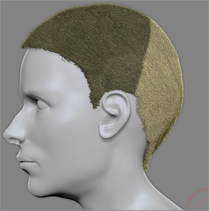
Figure 9-12: Lengthen the hair on the back of the head; then use the Smooth and GroomHairLong brushes to keep it fairly neat.
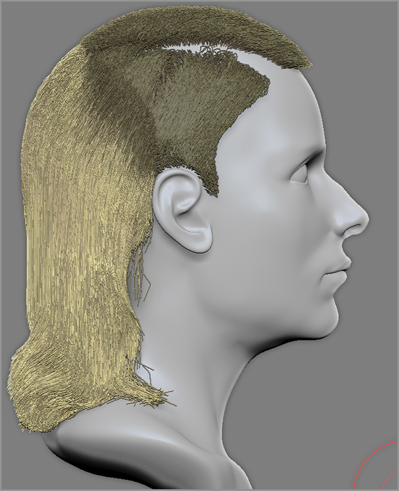
Figure 9-13: Pull the hair out on the side to match the length on the back of the head.
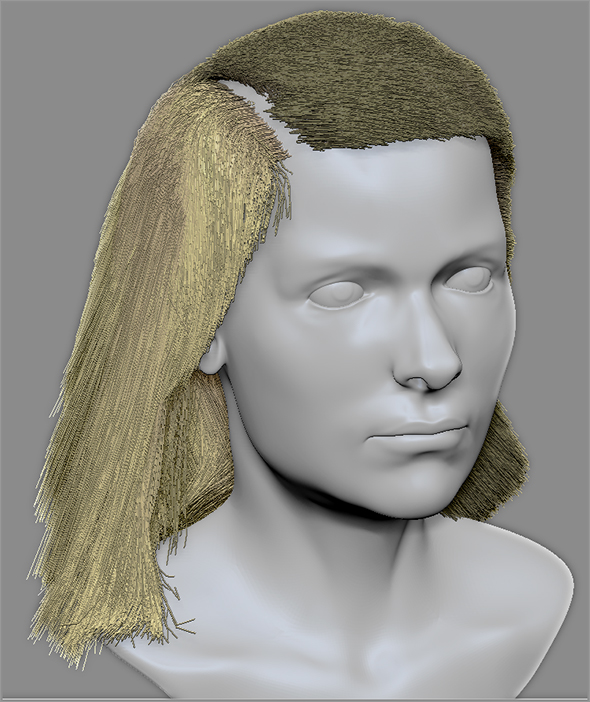
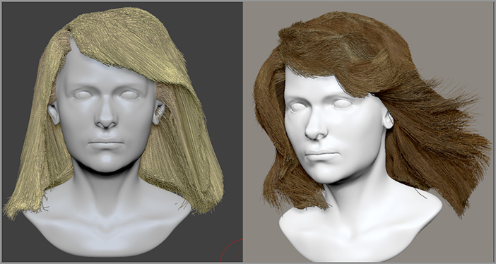
Figure 9-14 (left) shows the hair after it has been lengthened. The image on the right shows the finished hairstyle. I used the GroomColorize brushes to change the hair color to brown.
Figure 9-14: The hair is lengthened and then styled and colored using a variety of special grooming brushes.
- If the ends of the hair are uneven in length, hold the Shift key and lower the Preserve Length setting in the FiberMesh subpalette of the Brush palette. The Smooth brush averages the length of the hair within the area of the brush tip and smooths the ends of the hair to make them less frayed.
- Always have a reference nearby! You can use fashion magazines, image searches on the Internet, shampoo commercials, or whatever else you can find. Styling hair without a reference is asking for trouble!
- Store a Morph Target by clicking the StoreMT button in the Morph Target subpalette of the Tool palette. Then as you work you can use the Morph brush to comb hair back to the stored state if it gets out of control. Chapter 10 discusses using Morph Targets in more detail.
- Some of the Groom brushes will paint colors on the hair as you work. If you’re not ready to color hair, turn off the Rgb or Mrgb button on the top shelf. These buttons are enabled for some brushes and not for others.
- Experimentation is the key; try each of the grooming brushes and see which ones you like. Personally I find the GroomHairTips brush to be a huge benefit since it has a stronger effect on the tips of the hair. It makes it easier to create layering. The GroomHairToss brush is great for shaping the hair. Try different alphas and Z Intensity settings as you work. If you create a brush you like, save it!
- Once you have a decent style, start adding some color using the GroomHairColorizer brush. Brushes such as GroomRootColorize, GroomMidColorize, and GroomTipColorize allow you to add variations in hue to specific parts of the hair.
- Later in this chapter you’ll learn how to render the hair realistically using the hair materials.
- There are many advanced capabilities within FiberMesh that can be used for more than just hair. Some advanced techniques allow you to use FiberMesh to place leaves on trees and create whiskers and eyebrows. For more information check out the free movies at the ZClassroom at www.pixologic.com.
Rendering Basics
In CG terms “rendering” refers to the process where software creates an image from the models, lights, and materials that you have put together. Many 3D software packages, such as Autodesk® Maya®, use very complex systems to create realistic images. ZBrush also has the capability to create compelling and realistic images from the models you sculpt on the canvas. However, in ZBrush, rendering is a bit simpler and faster than in other software packages.
Rendering, lighting, and materials are all areas that work together when creating an image. The examples in this section are designed to give an overview of how these elements work together and how you can use them creatively to express your own artistic vision. We’ll start with an overview of the render modes available in ZBrush.
Render Modes
There are five render modes available in ZBrush: Flat, Fast, Preview, Best, and Best Preview Render (BPR). Each mode offers advantages and features ranging from improving performance while working to creating realistic or stylistic images. The following list gives a brief description of each mode:
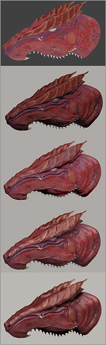
Figure 9-15 shows a painted dragon model in each of the five modes.
Figure 9-15: The dragon model is shown in the five render modes from top to bottom: Flat, Fast, Preview, Best, and Best Preview Render (BPR).
To switch renders using Flat, Fast, Preview, or Best, open the Render palette and choose one of the buttons at the top. To render using BPR, click the BPR button at the top of the right shelf, as shown in Figure 9-16, or press Shift+R. Both Best and BPR will take anywhere from a few seconds to a few minutes to render depending on the complexity of the model, the lighting, and the render features you have chosen.
When using Best quality to render an image, the render will update automatically each time you make a change. If you need to stop a render, just press the Esc key. To start it again, click the Render button in the Render palette.
To save you render time, ZBrush stores information about the previous render in a buffer. This means that, as long as you don’t change the view of the model, the next time you render using BPR or Best mode, the render should be much quicker.
The Render palette contains myriad options to customize how the render will look. The examples in this chapter will cover the basics of some of these settings.
Figure 9-16: To choose a render mode, select from the options at the top of the Render palette. To render using BPR, click the button at the top of the right shelf, which is circled in this image.
You can render any time while working on your models. It’s a good idea to switch render modes often while sculpting to understand how the surface interacts with light and shadow.
Once you create a render, you can export the image by clicking the Export button in the Document palette. You can choose from many popular image formats including Photoshop (PSD). Later in the chapter you’ll learn how to render individual passes that can be composited in Photoshop. This is a popular way to separate rendering elements such as shadow, diffuse light, depth, and other passes so they can be adjusted and recombined into a Photoshop composition.
The size (or resolution) of the exported document is determined by the current document size in ZBrush. You’ll learn more about these techniques, as well as how to set up a ZBrush document for export to Photoshop, at the end of the chapter in the section titled “ZBrush and Photoshop.” This section walks you through the process of setting up a high-quality render for export to Photoshop at a specific resolution. But before we get there, we need to cover the fundamentals of lighting and materials!
Standard Lighting
Standard lighting in ZBrush is simple to use and yet very powerful. Using the controls at the top of the Light palette, you can change the direction of the light, add lights, and control light properties such as shadows, intensity, and ambience. The lights can be used to create a composition or as a sculpting aid. This section looks at how the standard light controls work and offers a few examples of how lighting can be used while sculpting and rendering in ZBrush.
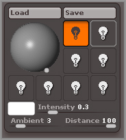
The Light Palette
All elements pertaining to lighting are controlled through the Light palette. Unlike other 3D software programs such as Maya, you don’t position representations of the lights in empty space; rather, you control the placement of lights using the sphere shown in the upper right of the Light palette. For this example, open a ZBrush project; you can use the DemonCar.ZPR project found in the Chapter 9 folder of the DVD or use one of your own.
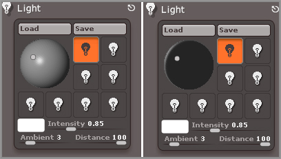
By default a single light is turned on in every ZBrush project; there is also a small amount of ambient light that affects everything on the canvas. To change the position of a light, drag on the small orange dot on the sphere in the Light palette. You’ll see the lighting update as you drag the orange dot across the sphere (see Figure 9-17).
Figure 9-17: Drag the orange dot across the preview sphere in the Light palette to adjust the position of the light.

You can use the light position as a sculpting aid. Real-world sculptors constantly move their lights around as they inspect their work. Different light angles reveal flaws in the surface that might not be noticeable otherwise. Press the Ctrl+P hotkey to activate interactive lighting while you work. As you move the brush over the canvas, the light updates automatically. Click on the canvas to stop moving the light. This saves you from going to the Light palette every time you reposition the light.
The area around the lighting control sphere is surrounded by light bulb icons. This area is the light switch panel, which lets you turn lights on and off. You can add up to eight standard lights in a ZBrush scene. If that’s not enough, later in the chapter you’ll learn how you can add as many lights as you like using LightCap.
Figure 9-18: An orange highlight on the light bulb icon indicates that the light is on. A gray border around a light bulb icon indicates that the light is selected.
To turn a light on, click one of the light bulb icons so it turns orange. Usually, you must click it twice—once to select the light and again to turn it on. When a light is selected, a gray border appears around the light icon. This means that when you drag on the sphere, you change the position of the selected light. Many of the sliders and controls in the Light palette affect the selected light. To turn a light off, click its icon until it is no longer highlighted in orange (see Figure 9-18).
Light Types
ZBrush uses four types of lights to illuminate the strokes and 3D tools on the canvas. By default, there is a single sun-type light that is turned on when you start a ZBrush session. Sun-type lights have no point source—all of their rays are cast in parallel to simulate light coming from a distant source. You place sun lights using the sphere icon in the light window.
Figure 9-19: Change the light type for the selected light using the buttons in the Lights Type subpalette of the Light palette.
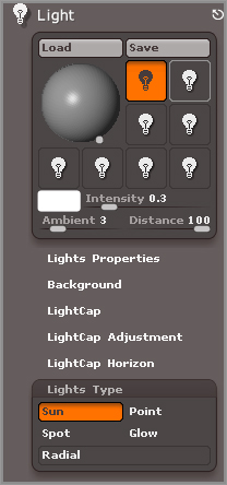
The other three types of lights are point, spot, and glow. To change the type of light you are using, click one of the buttons in the Lights Type subpalette. This changes the type of light currently selected (see Figure 9-19). Remember that the lighting you see on the canvas may not be coming from the currently selected light. Make sure the currently selected light is turned on when you change the settings if you want to see the lighting update accordingly.
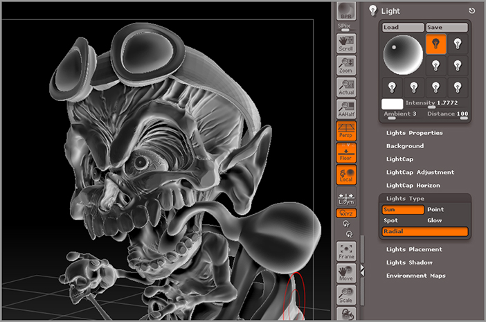
The Radial button at the bottom of the Light Types subpalette changes the behavior of the currently selected light so that the areas of the strokes or 3D tools that face away receive the light. This creates a good fill lighting effect. Fill lights simulate light coming from the sides of the subject. Any of the light types can be modified using the Radial button (see Figure 9-20).
Figure 9-20: The Radial button is a modifier that makes the selected light a fill light.
Sun Light
The following exercise will illustrate some of the differences between the types of lights:
Figure 9-21: The demon is lit with a simple two-light rig and rendered using BPR render mode.
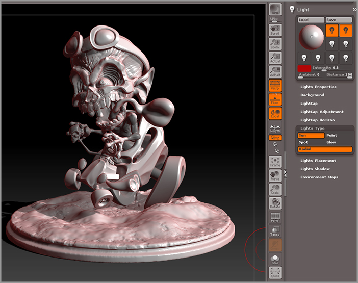
This is a simple two-light rig, not earth-shattering by any means but a good example of how to use the standard lighting controls for sun-type lights in the Light palette. In the next section, you’ll see how to use the point light type. Keep the same project open for the next section.
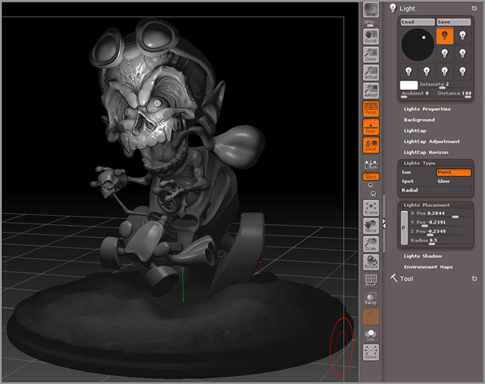
Point Light
The point light type works slightly differently than the sun-type light. To place the light, you’ll use the settings in the Placement subpalette of the Light palette instead of the preview sphere. Keep in mind that the point light type is visible only when rendering in Best render quality mode.
The point light emits light in all directions from a single point in space, like a candle. The radius determines how far the light from the point light travels in the scene.
Figure 9-22: The point type lights are positioned by dragging from the P button in the Placement subpalette to a location in the scene. Point lights render in Best mode and cast light in all directions.
You can combine point lights with other light types as a way to accentuate parts of the model or create mood lighting in a ZBrush illustration. In the next section, you’ll see how to use the spot light type. Keep the same project open for the next section.
Spot Light
The spot light type is positioned using both the preview sphere and the Placement subpalette. The preview sphere in the Light palette is used to position the light. The controls in the Placement subpalette are used to aim the light. Keep in mind that, like the point light type, the spot light type works only when rendering in Best mode.
Figure 9-23: The spot light type is positioned by dragging from the P button in the Placement subpalette to a location in the scene. Spot lights render in Best mode and create a pool of light cast from a single direction.
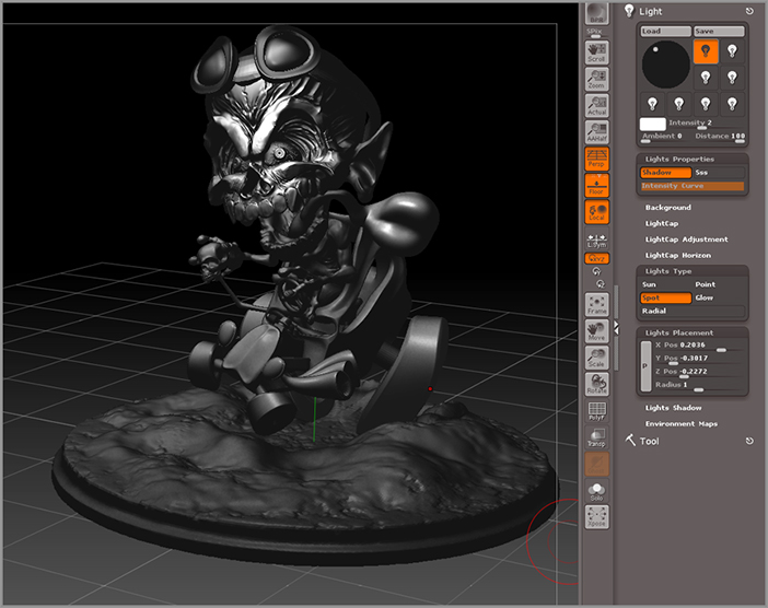
The spot light is similar to the point light. The main difference is how the lights are positioned. In the next section, you’ll see how to use the glow light type. Keep the same project open for the next section.
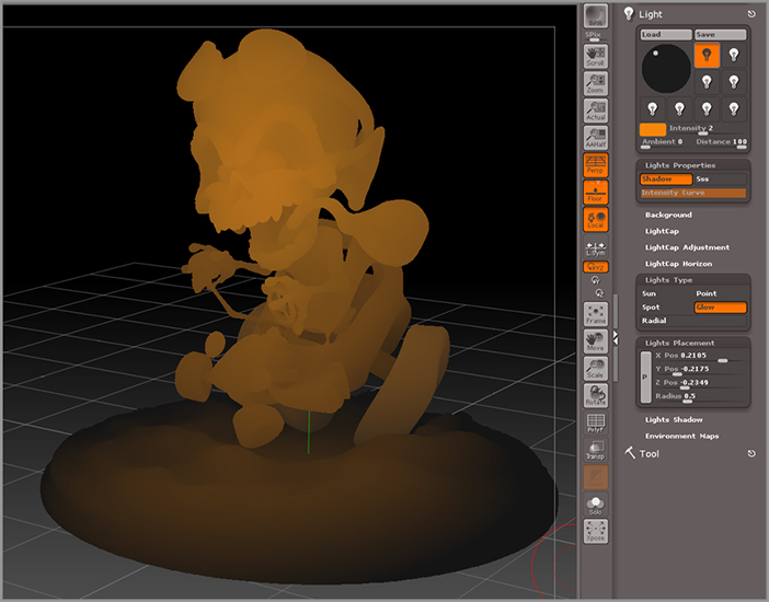
Glow Light
The glow light type adds ambient light that can tint parts of the model, adding an interesting look to the rendered image. Like point and spot type lights, glow type lights only render correctly using Best quality mode.
Figure 9-24: The glow light type is positioned by dragging from the P button in the Placement subpalette to a location in the scene. Glow creates an ambient light that radiates from a point in space.
Spend some time experimenting with different light types. Mix sun, spot, point, and glow lights in different combinations and test the results using Best quality render mode. Later in this chapter you’ll learn how to create an even wider variety of lighting effects using the advanced LightCap rendering system.
The Light Intensity Curve
The Light Intensity curve is an edit curve that works much like the curves you’ve used in other parts of ZBrush. This curve changes the intensity falloff of the light. By adjusting this curve you can design your own special light type. The following images show some effects you can easily achieve by playing with this curve (see Figure 9-25).
Figure 9-25: Use the Intensity curve in creative ways to create your own light types.
Shadows
You can render shadows using either BPR or Best quality rendering. To ensure that shadows render, turn the Shadows option on in the Render Properties subpalette of the Tool palette.
Figure 9-26: The controls for an individual light’s shadows are found in the Light palette (left). The controls for the global quality of BPR shadows are found in the Render palette (right image).
The settings for the type of shadows cast by a selected light in the Light palette are found in the Lights Shadow subpalette of the Light palette (see Figure 9-26, left image). To learn more about what each setting does, hold the Ctrl key and place the cursor over the setting.
The global controls for shadows when rendering with BPR are found in the BPR Shadow subpalette under Render Properties in the Render palette (see Figure 9-26, right image). To learn more about what each setting does, hold the Ctrl key and place the cursor over the setting.
If you want to cast shadows on the ground, activate the Floor button on the right shelf and then render using BPR. If the border of the grid clips the shadows, you can increase the size of the grid using the Grid S slider in the Draw palette.
Shadows rendered using BPR are sharper by default than shadows rendered when using Best quality. However, you can create a sharp shadow using Best quality by adjusting the Aperture setting in the Shadows section of the Light palette.
Advanced Lighting with LightCap
LightCap is another ZBrush term invented by Pixologic to refer to their unique advanced lighting technology; LightCap is short for “light capture.” LightCap works by creating a texture file that stores the lighting information that you create for the scene. This system is separate from the Standard lighting setup discussed in the previous section, but you can use the two together if you like.
The LightCap texture is mapped to a virtual sphere that surrounds the model. The color, position, and intensity of the lights are contained in this texture. The Details slider at the top of the Render Properties subpalette in the Render palette controls the resolution of the texture, so a higher setting creates more detailed lighting. You don’t need to work with the texture file directly; instead you’ll use the LightCap interface to add, edit, and remove lights from the scene. The interface and its controls are found within the LightCap subpalette.
The LightCap Interface
The LightCap interface is found in the Light palette. Expand the LightCap subpalette of the Light palette. This is where you add and position lights using LightCap. Follow these steps to create a basic LightCap lighting arrangement:
Figure 9-27: A new light is added to the LightCap editor.
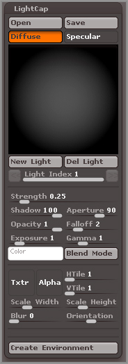
Figure 9-28: Create a graphic novel look instantly by raising the Aperture of a light and setting its Falloff to 0.
You can add as many lights as you want using LightCap. You can select a light and adjust its settings by clicking the orange dots on the sphere. If it becomes difficult to select individual lights, use the Light Index slider to select a specific light. The Light Index is incremented by one each time you add a light. If you want to delete a light, just select it and click the Del Light button.
That’s just a quick, fun example of how to add and adjust lights in LightCap. Of course, you can experiment to create many styles of lighting from stylistic to realistic. This will become more apparent as we delve deeper into the LightCap settings.
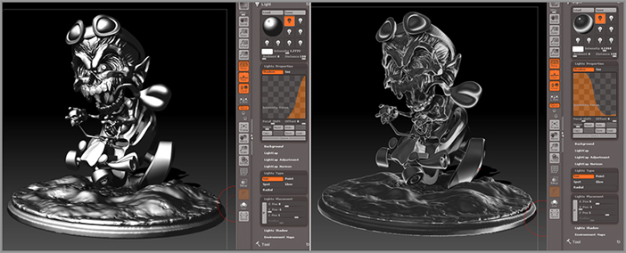
LightCap Settings
An interesting aspect of LightCap is that you can control the specular reflection of the light separately from the amount of diffuse lighting. To switch between Specular and Diffuse modes, click the buttons labeled Specular and Diffuse at the top of the interface. The Opacity slider controls how much influence the light has in this particular mode. In other words, if you want to create a light that just appears as a reflected highlight on the surface, set the Opacity slider to 0 while in Diffuse mode; then click the Specular button to switch to Specular mode and increase the Exposure slider to make the light brighter. To get a feel for this, add a light and practice switching between Diffuse and Specular modes. Adjust the Opacity while in either mode and make a mental note of the effect.
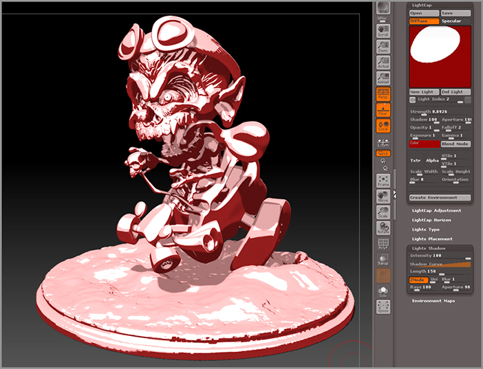
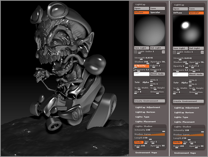
In Figure 9-29 two lights have been added to LightCap. The first light is only visible in Specular mode, since its Opacity has been set to 0 while in Diffuse mode. The second light is visible in both Diffuse and Specular modes. You can see the result on the model.
Figure 9-29: Two lights are added to LightCap. Opacity for Light 1 is set to 0 in Diffuse mode so it is only seen as a specular highlight on the model.
Strength, Opacity, and Exposure are different ways to control light intensity in LightCap. Strength is the overall presence of the light, Opacity controls the amount of specular or diffuse contribution the light makes in the scene, and Exposure has a multiplying effect on the brightness of the light.
Gamma controls the contrast of the light, which can also affect how bright the light appears. To keep things simple you may want to stick to controlling light brightness using Strength and Opacity.
LightCap lights cast shadows just like standard lights. The Shadow slider controls the intensity of the shadow cast by the selected light.
The Create Environment button creates a background image that matches the LightCap light rig.
The Blend Modes menu lets you set a specific blending mode for the light. These modes are similar to the modes found in image-editing programs such as Adobe Photoshop.
LightCap Alphas
You can apply an alpha texture to a LightCap light to shape the look of the light on the surface. This is a great way to create a studio lighting effect, especially when rendering hard-surface objects such as cars and robots, as shown in Figure 9-30.
Figure 9-30: An alpha texture is applied to the Specular mode of a LightCap light to simulate a studio-style lighting effect.
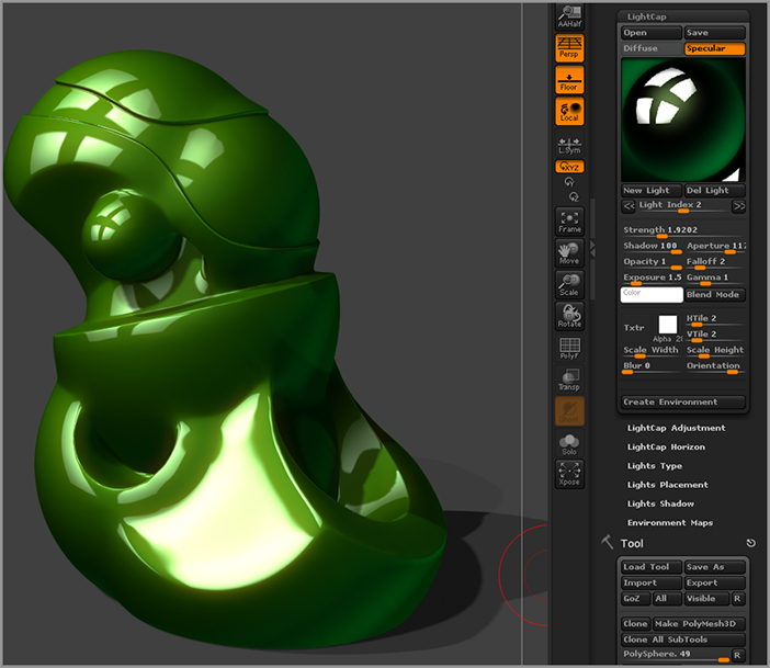
To add an alpha, select a light in LightCap and click the Alpha button. This opens the alpha library. Choose an alpha such as the white square. Alphas look best when they are applied only to the specularity of the light source, so try setting the Opacity in Diffuse mode to 0. Use the HTile and VTile sliders to create a repeating pattern. The Orientation slider can be used to rotate the alpha, and the Scale Width and Scale Height sliders can be used to scale the alpha.
For an example of how this setup looks, load the thingy.ZPR project from the Chapter 9 folder on the DVD.
Using a Background Image
One of the most interesting aspects of LightCap lighting is creating a lighting rig based on a panoramic image. This means that you can easily integrate one of your models into an image. The following exercise demonstrates how this can be done.
Figure 9-31: Load one of the images from the Panoramas folder in the Textures section of LightBox.
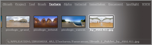
Figure 9-32: Select the texture by clicking the texture swatch in the Background subpalette of the Light palette.
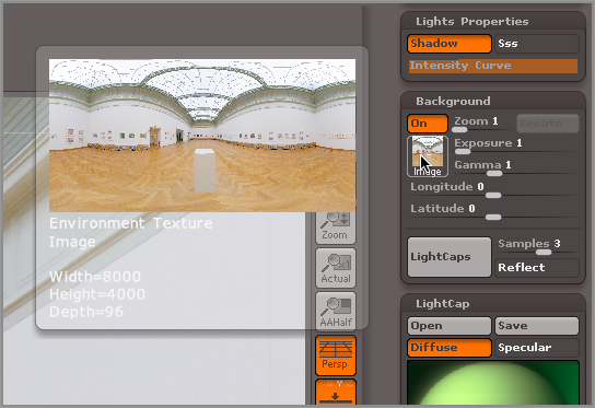
Figure 9-33: Use the gridlines to align the view with the corner of the room. You can make the lines darker using the settings in the Draw palette.
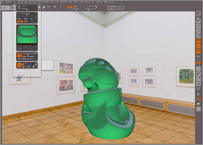
Figure 9-34: The image is rendered using BPR. The lighting and shadows help integrate the ZBrush model into the background image.
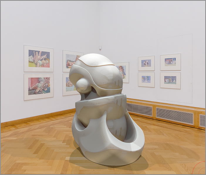
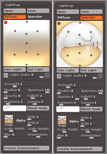
You can further improve the realism of the render by turning on the Ambient Occlusion option in the Render Properties of the Render palette. This will cause the render to take much longer, though. If you use the Longitude and Latitude sliders in the Background subpalette of the Light palette, the lighting will rotate to match the background. Figure 9-34 shows the render with Ambient Occlusion activated. Figure 9-35 shows how the LightCap uses the lighting from the image in both the Diffuse and Specular modes. You can continue to add and edit lights after creating a LightCap from a panorama.
Figure 9-35: The LightCap is created by sampling the panorama in the background. You can see how the lights are placed in the Diffuse and Specular modes.
You can use panoramas in many creative ways. Many websites let you download panoramic images to be used as LightCaps. One of my favorite websites is the sIBL archive at http://www.hdrlabs.com/sibl/archive.html. You can use JPEG format panoramas or HDR panoramas, although JPEGs will render faster than HDR format images.
Saving LightCap Files
If you create a LightCap rig that you like and want to reuse for future modeling projects, use the Save button in the LightCap subpalette to save the rig in a special ZLD format. Use the Load button to load any LightCaps you may have saved. You’ll also find examples of LightCap rigs in the Project/LightCap Projects folder in LightBox.
Material Basics
ZBrush materials determine the surface quality of your model. They are what make the model appear shiny, dull, waxy, or skinlike. There are many types of materials, but generally speaking the materials are divided into two major categories: Standard and MatCap. Standard materials are edited by adjusting sliders in the Modifiers subpalette of the Material palette. MatCap materials are based on a texture that includes light information that is baked into a texture and then applied to the surface.
Standard and MatCap materials can be mixed together to create some really interesting effects. This section will provide you with an overview of how to work with materials before diving into the details of how Standard and MatCap materials work.
Material Shaders
Materials are made up of shaders. A material can have from one to four shaders that are layered together. Each shader is just a list of properties that define how the surface reacts to light when rendered. The shaders occupy slots that are stacked together from left to right at the top of the Modifiers subpalette in the Material palette (see Figure 9-36). The slots are labeled S1, S2, S3, and S4. Each slot can contain different types of shaders or variations of the same shader in any combination. You switch from one shader to the next by clicking the slot buttons (S1, S2, S3, S4). Some materials have just a single slot available, while others have more. Shaders can be turned on and off by clicking the little circle in the slot button. If the slot button is highlighted, then the slot is selected, and all the modifier controls below affect that shader. If the circle is open, the shader is on; if it is closed, then it is off and will not affect the current material. As with lights, it is possible to modify a shader that has been turned off. If nothing happens when you adjust a shader’s sliders, double-check to see if the shader has been turned off. If the shader slot button is grayed out, then the shader is unavailable for that material. Figure 9-36 shows the shader slot buttons for the TriShader material, which has three of the four shader slots available.
Figure 9-36: The TriShader material has three of the four slots available. The highlighted button indicates the selected shader. The small circle turns the shader on or off.
The ability to layer shader slots can lead to a near-infinite number of possibilities for creating material properties. The amount of influence one shader has on the material is determined by the settings in the Shader Mixer subpalette of the Material palette. But before we get into how shaders are mixed together, it’s important to get a handle on working with individual shaders. You’ll learn more about the Shader Mixer in the section titled “Paint Materials” later in this chapter.
Copying and Pasting Shaders
The process of creating and editing ZBrush materials is, like all things ZBrush, unique. You may have noticed that there is no button for creating a new shader. You can’t add a shader to an existing material either. If you’re used to working in a program such as Maya, this is a weird concept to wrap your head around. So how do you create a new shader? You actually copy and paste an existing shader from one material to another. As you’ve seen in previous chapters, ZBrush has a large number of presets. Some of these preset materials are set up to create a particular effect, such as metal, skin, or plastic. Other materials are simply generic presets available for you to edit. This example shows how you can create a new material preset by copying a shader from one material into another.
Figure 9-37: Select the ReflectedMap material from the material library.
Figure 9-38: Switch to the S1 slot in the Modifiers subpalette of the Material palette.
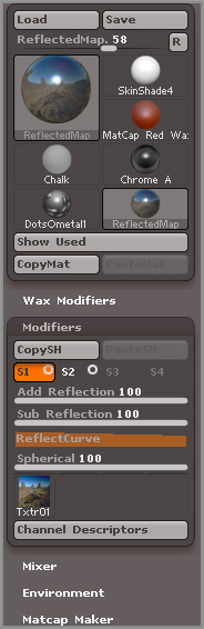
The PasteSH button is available only when a shader has been copied to the clipboard. This is how you create a new material by copying and pasting shaders and settings from one material to another. It’s an odd approach to building materials, but it’s pretty simple once you get the hang of it.
You can also copy an entire material and paste it over another material. To do this, select a material from the library and click the CopyMat button in the Modifiers section of the Material palette. Then select another material and click the PasteMat button. The settings and shaders of the selected material will be replaced with the settings and shaders of the copied material. This is a good way to quickly create duplicate materials in case you want to make variations of one of your own custom presets.
Figure 9-39: Copy the settings from the S1 slot of the ReflectedMap shader and paste them into the S2 slot of the TriShaders material.
Saving Materials
So what do you do once you’ve created a new material that you like? Save it, of course! ZBrush uses its own ZMT file format to store material information. You can quickly build up your own library of materials for use on all your ZBrush models. Use the Save button at the top of the Material palette. This opens your computer’s file browser. If you save the material file in the ZBrush 4R3/ZStartup/Materials folder, the file will appear in the material library the next time you start ZBrush. Alternatively, you can save the file in the ZBrush 4R3/ZMaterials folder; then the preset will appear in the Materials section of LightBox.
Downloading Materials
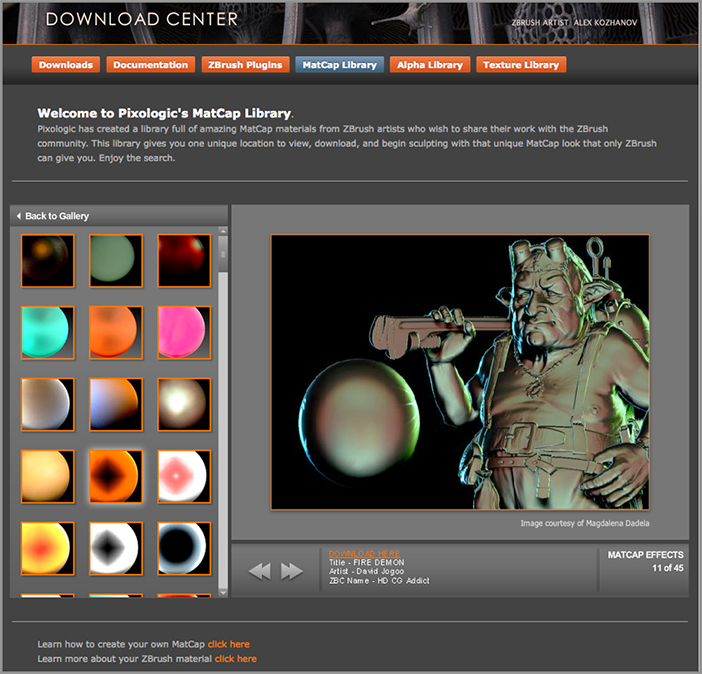
ZBrush artists love to create and share their own materials. Many artists use the forums at ZBrushCentral to share their materials and material-editing techniques. You can also find hundreds of free materials on the Pixologic home page; just point your browser to www.pixologic.com/zbrush/downloadcenter/library/ (see Figure 9-40). You can preview the materials on the Web; download the ones you like and load them into ZBrush.
Figure 9-40: Hundreds of materials are available for free download at Pixologic’s home page.
Designing Materials
By editing existing materials you can design your own presets. This section takes you through the process of designing some original materials.
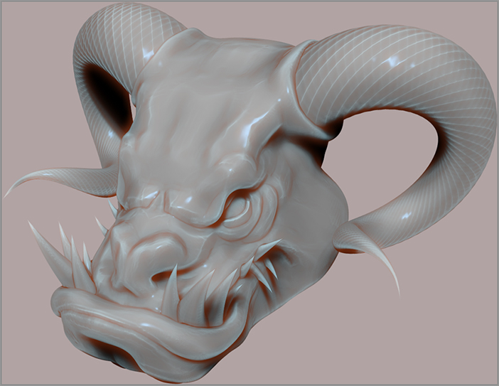
Understanding MatCap Materials
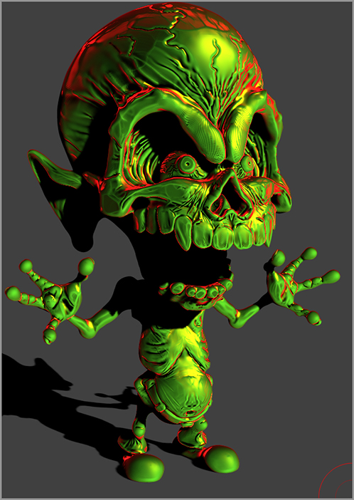
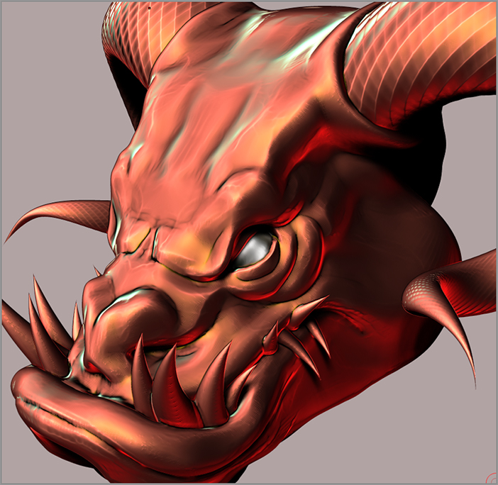
MatCap stands for “Material Capture.” This type of material captures lighting information and bakes it to a texture. It’s very similar to the way LightCap works when designing lights. In fact, you can use the LightCap editor to create your own MatCap. This example shows you how to use LightCap to make a demonic cartoon-style shader for the demon character:
Figure 9-41: As lights are added to LightCap, the appearance of the MatCap Red Wax material is updated to match the lights.
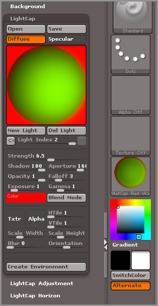
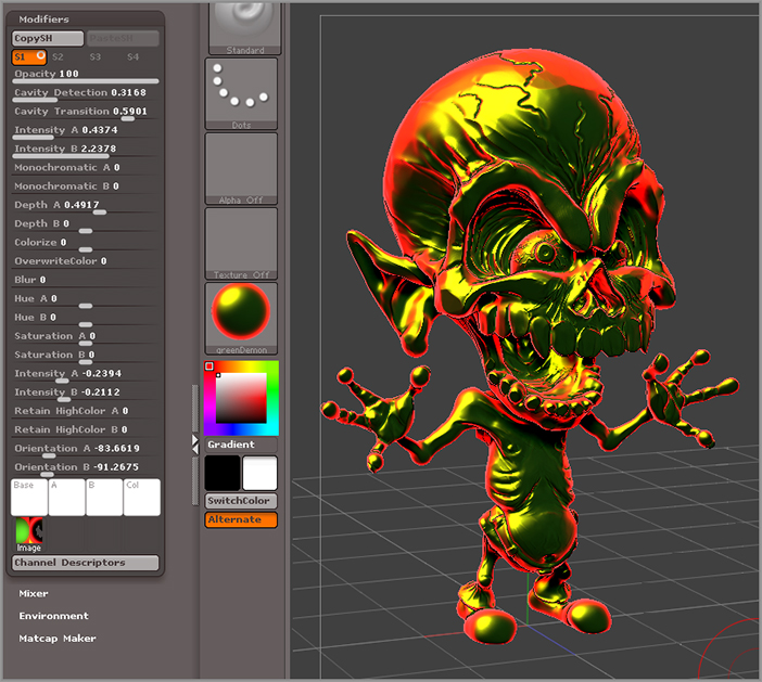
Now you have a rather stylistic LightCap arrangement that is just perfect for cartoons. If you look in the Material palette, you’ll see that the MatCap Red Wax material has taken on an appearance very similar to the preview in the LightCap window except that the material shows both the Diffuse and Specular components at the same time (see Figure 9-42).
Figure 9-42: The MatCap material has been created via the LightCap interface.

Figure 9-43: The MatCap material has been created via the LightCap interface.
Editing a MatCap Material
You can continue to alter the properties of a MatCap material after you create it using the sliders in the Modifiers subpalette of the Material palette.
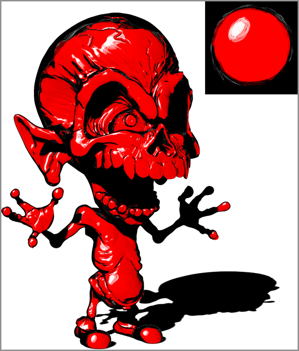
Figure 9-44: The MatCap material has been created via the LightCap interface.
Notice that the image has two circles. The circle on the left corresponds to the Diffuse channel of the LightCap, and the circle on the right corresponds to the Specular channel (see Figure 9-44). If you examine the properties of other MatCap materials, you’ll see that some of them use two circles and some use just one.
If you take a look at the sliders in the Modifiers subpalette of the Material palette, you’ll see that many of the properties are in pairs labeled A and B. For example, with Intensity A and Intensity B, the sliders labeled A control the influence of the left circle in the texture, and the sliders labeled B control the influence of the right circle. For those MatCap materials that have only a single circle, the B slider has no effect.
You can also change the direction of the light by adjusting the Orientation A and Orientation B sliders. This can be very useful because, although the standard lights do not affect the appearance of surfaces that use the MatCap materials, the surface they are applied to does cast and receive shadows, and you’ll want to make sure that the highlights and other lighting effects match the direction of the shadows. The Orientation sliders can help you do this (see Figure 9-45).
Figure 9-45: Adjust the sliders in the Modifiers subpalette of the Material palette to create variations of the material.
The colors you paint on the surface of the model are blended with the colors of the material. Currently, the color of the demon is white, but if you change the color in the color picker, the color of the surface is blended with the color of the material. You can control how much the material colors override the surface colors by increasing the OverwriteColor slider.
Painting Materials
So far you’ve been applying materials to the entire surface simply by selecting materials from the material library. You can also paint materials directly onto the polygons of a surface. In addition, you can use the Shader Mixer to determine how the shaders of the material are mixed together based on various surface properties. This section takes a look at some ways in which materials can be applied to your surface.
Polypainting Materials
The techniques for painting materials on a surface are very similar to the polypainting techniques you learned in Chapter 8. You can paint a material directly onto the polygons of a mesh using the sculpting brushes. There are a couple of tricks you can use to improve the look of the painted materials when rendering with BPR.
Figure 9-46: Click the M button on the top shelf to switch to Material mode; then use the FillObject button in the Color palette to fill the model with the current material.
You won’t notice an immediate change, but if you switch materials in the material library, the surface should no longer update.
You’ll notice that the material is applied to the entire polygon. Unlike polypainting, the materials are not blended across the surface, so the border edge where two materials meet looks very jagged. Don’t worry though; that’s an easy fix!
Figure 9-47: Use the Standard brush to paint the MatCapMetal02 material onto the eyeballs.
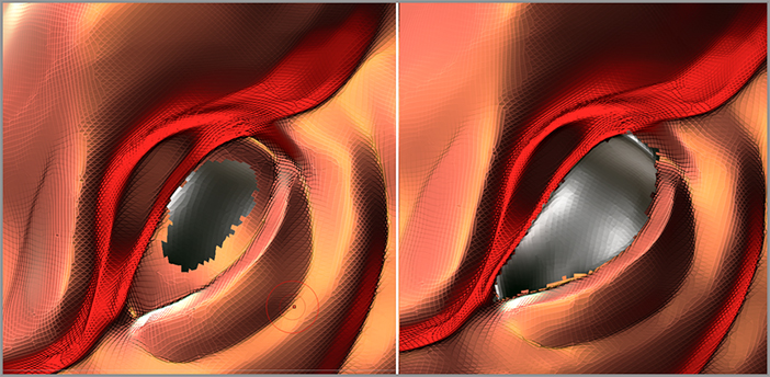
Figure 9-48: Set the Materials Blend-Radius in the Render palette to 3.
Figure 9-49: The border between the materials is blurred when rendered with BPR, resulting in a smooth transition.
This works well in most situations. There isn’t a way to directly adjust the opacity of materials. However, there is a way to indirectly adjust the opacity of shaders, which can allow you to create much more subtle transitions between material properties. This is done using the Shader Mixer.
The Shader Mixer
The Shader Mixer is a subpalette located below the Modifiers subpalette in the Material palette; see Figure 9-50. The sliders in the Mixer subpalette are active for any material that has more than one shader. The sliders determine how visible the shader is on the surface based on a variety of properties. For example, you can use the ByShadow slider to make a shader more prominent in the shadowed areas than in the lit areas. It is an amazingly powerful tool, especially when used in materials with three or more shaders. Each shader can have its own Mixer settings, leading to a wide variety of interesting material effects. In this section you’ll get a sense of how to work with the Mixer on a simple example.
Figure 9-50: The Shader Mixer controls are found in the Mixer subpalette of the Material palette.
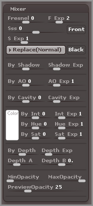
Figure 9-51: Turn off Shader 1 using the circle switch on the S1 button so that you can focus on Shader 2.
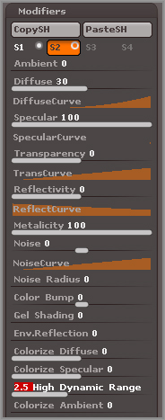
The result is a dark, shiny, gray shader, as shown in Figure 9-52. Metallicity caused the highlight to be influenced by the hue of the underlying surface color. Setting this to 0 ensures that the specular highlights will be white, making them look very glossy. High Dynamic Range boosts the intensity of the colors.
Figure 9-52: The S2 shader settings create a dark and shiny material.
Figure 9-53: Choose the Screen blending mode from the Blend Modes menu in the Mixer subpalette.
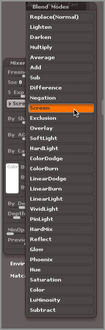
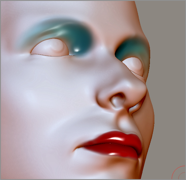
Figure 9-54: The Mixer settings tell ZBrush to make the shiny S2 shader appear only on the parts of the surface that have dark, saturated colors. This makes the lips appear glossy when they are painted dark red.
Using this technique, the Rgb Opacity slider controls not only the opacity of the colors but also the opacity of the S2 shader. Try painting a light blue color fading to a dark blue color in the area above the eyes. The dark blue color should appear a little shinier than the lighter blue colors. If you rotate the head and the light in the Light palette, this is easier to see (see Figure 9-55).
Figure 9-55: The intensity and opacity of the painted colors determine the intensity and opacity of Shader 2 so you can use color to blend areas, making them increasingly shiny as the color gets darker.
You can also use the Mixer to make a material appear only in shadowed areas, or just in cavities, or in areas where ambient light is occluded (AO). To see some of these effects you’ll need to render using BPR. The options can be mixed and matched and varied in strength, allowing for infinite possibilities.
For additional practice you can experiment with one of the projects that comes with ZBrush. The TwoTone_Beetle.ZPR project found in the Projects section of LightBox is a simple PolySphere that has been set up so that as you paint light colors on the surface of the sphere, the materials appear dull, and as you paint dark colors on the surface it appears shiny.
BPR Rendering Techniques
This section demonstrates some of the more advanced features of the BPR rendering system. These techniques can be combined creatively in your ZBrush projects.
Subpixel Anti-Aliasing Quality
As discussed in Chapter 1, anti-aliasing refers to a trick used by graphics software packages to improve the quality of the edges of a digital image. All images created on a computer are made up of tiny colored squares known as pixels. Without anti-aliasing, these tiny squares are clearly visible along the edges of an object on a computer screen, which gives the image a jagged appearance. The process of anti-aliasing blends the colors of the edges together, creating a softer appearance for the edges.
When rendering with BPR you can control the amount of anti-aliasing using the SPix slider on the top of the right shelf (see Figure 9-56). To increase the quality of the anti-aliasing in the rendered image, increase the value of the SPix slider. Note that higher values will increase the time it takes to create the render.
Figure 9-56: The SPix slider on the right shelf controls the anti-aliasing quality when rendering with BPR.
Ambient Occlusion
Ambient occlusion is a popular way to simulate the look of diffuse lighting in computer graphics by using soft shadows in the cracks and crevices of 3D objects. The settings on the Bpr Ao subpalette of the Render palette allow you to balance the quality of the ambient occlusion shadows with the time it takes to render them.
To create ambient occlusion shadows, ZBrush creates an array of virtual lights in a sphere around the model. Each light casts a shadow, and the shadows are blended together. You don’t actually see the lights in the scene, just their shadows. Models rendered with ambient occlusion tend to look solid and realistic. The settings in the Bpr Ao subpalette of the Render palette adjust the quality of the ambient occlusion shadows. To learn how each slider works, hold the Ctrl key and place the cursor over the name of the slider. These settings are similar to settings used to adjust the BPR shadow quality.
The following short exercise demonstrates a useful workflow for adding ambient occlusion to BPR renders:
Figure 9-57: In the Render palette turn off Shadows and turn on AOcclusion.

Figure 9-58: The model is rendered using ambient occlusion and the Chalk material.
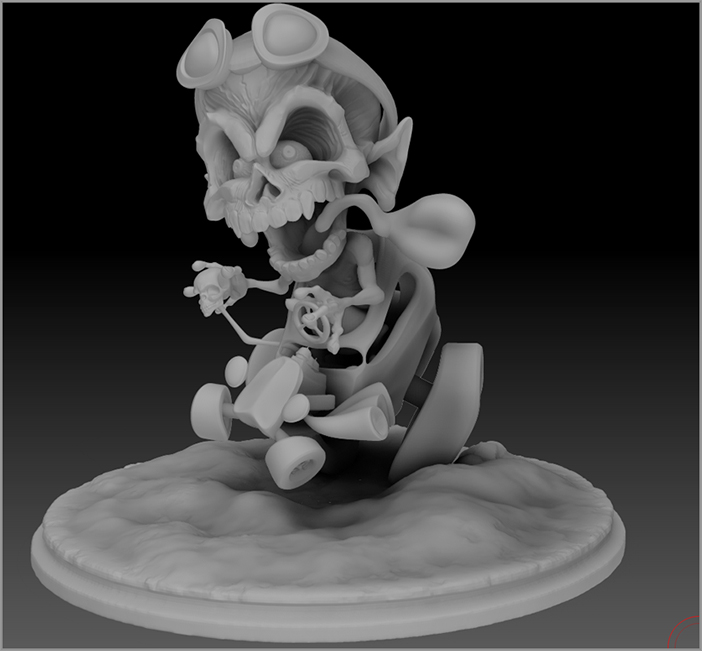
You’ll see the model with just the ambient occlusion shadowing. Try experimenting with the settings to see how you can change the look of the ambient occlusion shadowing. You can turn on the Spd button in the Bpr Ao subpalette of the Render palette to speed up render times while testing. Turning Spd off excludes ambient occlusion from the subpixel anti-aliasing calculations, resulting in a faster render. In addition, after the first time you render with ambient occlusion activated, ZBrush stores the calculations in temporary memory. If you do not change the view of the model, ZBrush will use this information so that it does not need to recalculate the ambient occlusion shadowing. This makes testing renders much faster. But if you change the view of the model, then the calculations will need to be re-created on the next render.
Subtool Transparency
When rendering with BPR, the Transparency controls in the material transparency don’t work. Instead, you use the controls in the Tool palette to determine which subtools will render as transparent, and then the settings in the Render palette determine how the transparency works. This exercise walks you through the process for rendering transparent surfaces in ZBrush.
Figure 9-59: Turn on Transparent in the Render palette and then activate BPR Transparent Shading for the Shield subtool in the Tool palette.
Figure 9-60: The character’s face is now visible through the transparent shield.
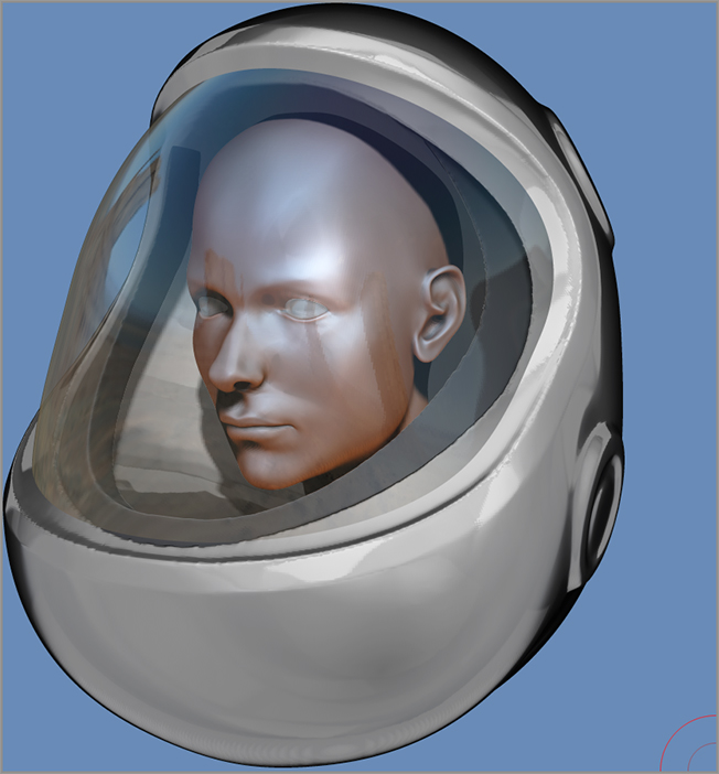
The reflections are not physically accurate; rather, they are baked into the material itself. If you want to reflect a specific image, you can use MatCap or LightCap lighting as demonstrated earlier in the chapter.
Figure 9-61: The quality of the transparency is defined using the controls in the BPR Transparency subpalette of the Render palette.
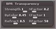
To control the transparency, use the BPR Visibility slider and lower the value to make the subtool render as less transparent. You can also use the settings in the BPR Transparency subpalette of the Render palette to set global properties for transparency (see Figure 9-61).
The Strength slider sets the overall strength of the Transparency.
The NFactor slider determines how the normal direction of the surface affects transparency. Low values mean the edges that face away from the viewing angle are less transparent than the areas of the surface that face the camera. A high value means that more of the surface is opaque.
The ByColor setting causes the transparency to be affected by the color intensity of the surface.
The CFactor setting determines how the color influences the transparency of the subtool. Think of it as a way to set a threshold value. When CFactor is at a low value, colors darker than white will make the surface appear transparent. When CFactor is at a high value, only the darkest colors will appear transparent.
The Refract slider creates the look of refraction, which is the distortion you see when looking at an object through thick glass. ZBrush refraction is not physically based, so it is limited in how realistic it can make refractions appear.
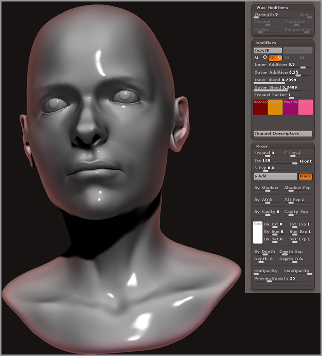
Wax Preview
Wax Preview creates a somewhat translucent effect in the surfaces you render with BPR. You can also preview the wax effect while you are sculpting your models in the Preview render mode. Each ZBrush material can have its own wax setting. Here’s how you can use this feature.
Figure 9-62: Activate WaxPreview in the Render palette and set the Wax Modifier Strength to 100 in the Material palette.
The sliders in the Wax Modifiers section affect how the wax effect appears in a BPR render; they do not affect the preview of the wax that you see while in Preview render mode. To learn more about how each slider affects the quality of the BPR render, hold the Ctrl key and place your cursor over the slider.
Figure 9-63: WaxPreview gives the model a slightly translucent effect.
Subsurface Scattering
The Subsurface Scattering option in ZBrush simulates the luminescent quality of the skin. As photons of light penetrate the layers of skin they bounce around, pick up the color of the deeper layers of tissue, and then exit the skin, giving it a kind of glow. This helps make the model look as though it is made up of living flesh. In many 3D packages this effect is simulated by more or less replicating the physical properties of light. In ZBrush the effect is created using a gradient of colors; this is a cheat rather than a physical simulation of light, but it’s an effective one!
Working with subsurface scattering (SSS) in ZBrush is a little tricky since there are a few ways to create this effect and the interface is not terribly intuitive.
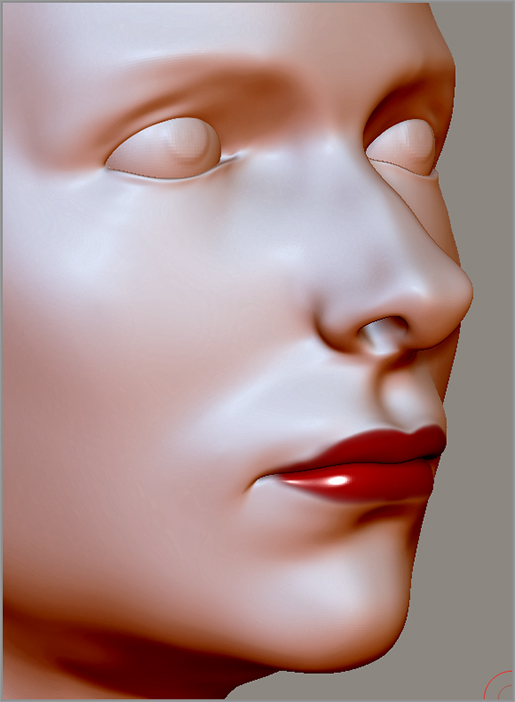
In this example you’ll learn how to set up subsurface scattering on the female head model. This will add a hint of reddish color that is stronger on the thinner parts of the model, such as the ear.
Figure 9-64: Activate Sss in the Render palette. Turn off the S1 shader and turn on the S2 shader for the FresnelOverlay material.
The color swatches at the bottom control the colors used in the gradient; the sliders at the top control the amount of influence of each color. The shader is essentially a way to mix the colors. The Fresnel Factor slider controls the strength of the gradient based on the viewing angle of the surface. You’ll want to test render using BPR as you change these settings to get a sense of how they work.
The colors I’m suggesting and their values are fairly subjective and will change depending on the model. You’ll most likely want to tweak them as you work. These warm colors are meant to give the impression of tissue beneath the skin. At the moment the gradient is applied to the entire surface. The Fresnel Factor slider is going to shift the gradient colors toward the edges when it’s set to a positive value and toward the center when it’s at a negative value. And you’ll tweak many of these settings once you start putting the material together, but at least now you have a place to start.
Of course, this is just a gradient; it’s not subsurface scattering just yet. To finish the basic effect you need to adjust some settings in the Mixer.
Figure 9-65: The settings for the FresnelOverlay shader are shown on the right. The left image shows the model rendered using BPU with both the S1 and S2 shaders turned on.
Many ZBrush artists will copy the FresnelOverlay shader into the S2 slot of the TriShader material and then use the S1 shader settings to control the diffuse properties and the S3 shader settings to create the specular properties of the material.
Figure 9-66: Turn on SSS Across Subtools when using subsurface scattering on multiple subtools.
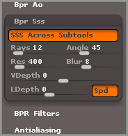
There are additional settings that control the quality of the subsurface scattering effect in the Bpr Sss subpalette of the Render palette. Most times you can leave these settings at their default values. The most important of these settings is SSS Across Subtools, which is off by default. If you are rendering subsurface scattering on multiple subtools at the same time, turn this option on (see Figure 9-66). Otherwise the subsurface scattering is calculated for each subtool individually, which does not look realistic.
Rendering Hair
Rendering hair created with FiberMesh is very easy; there are only a few settings you need to worry about to get a good result. These settings are found in the Tool palette at the bottom of the FiberMesh subpalette. There are also two Hair material presets that can help your hair look shiny and more realistic. Rendering hair can take a while, so it’s a good idea to start with fairly low-quality settings in the FiberMesh subpalette and then gradually raise the settings and test while you go. This will save you some time because often you’ll find that low-quality settings will still produce a very believable effect.
This example walks you through the basics of rendering hair created with FiberMesh.
Figure 9-67: Activate the M button on the top shelf to switch to Material mode.
Figure 9-68: Select the Hair material from the material library (left). Click the FillObject button in the Color palette (right).
Figure 9-69: Adjust the settings at the bottom of the FiberMesh subpalette of the Tool palette.
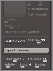
You can continue to adjust the settings to get the look you want to achieve. The Root and Tip Anisotropy sliders control the rotation of the specular highlights along the length of the hair. If you want to make the hair look more or less shiny, you can experiment with these settings as well as the specular strength of the Hair material. Figure 9-71 shows the hair with a Radius of 0.1 and Subdivision level of 3. Specularity has been increased in the Hair Material modifiers.
Figure 9-70: The hair is rendered at lower-quality settings using BPR.
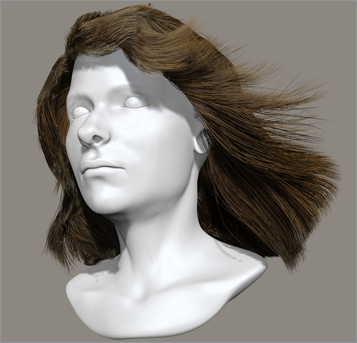
Figure 9-71: The hair is rendered at higher-quality settings using BPR.

BPR Render Filters
BPR render filters are a great way to enhance your render after it has completed. The filters allow you to make adjustments and create effects without having to re-create the render or go to an external image-processing program such as Photoshop. BPR stores much of the information concerning depth, shadows, and ambient occlusion in memory after you create a render, so as long as you don’t change the view or sculpt the model, you can apply the filters, make adjustments, and view the changes in real time. The following example demonstrates how to add depth-of-field blurring and other color adjustments to a render.
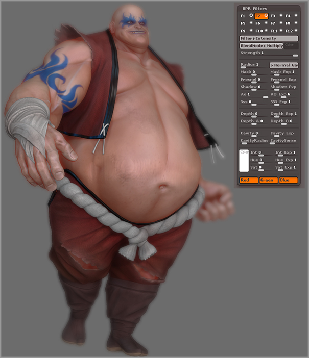
Figure 9-72: Load the Kotelnikoff_Earthquake.ZPR project from the Project section in ZBrush.
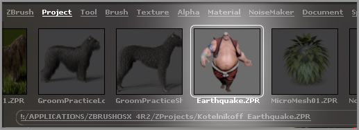
Figure 9-73: The BPR Filters subpalette of the Render palette
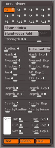
Each filter is stored in a channel slot. The buttons labeled F1 to F12 hold the settings for each filter, so you can apply up to 12 filters. Each filter is layered on top of the previous filter as you add it. The default F1 filter adds noise to the render. You can change this to get a different effect. Let’s try adding some depth-of-field blurring to the render so that the parts of the character that are farther from the front appear blurry. I think it makes it easier to see how this works if you exaggerate the strength of the blurring, adjust the filter to set the depth, and then fine-tune the settings. Follow these steps to see what I mean.
Figure 9-74: Set the BPR render filter to Blur.
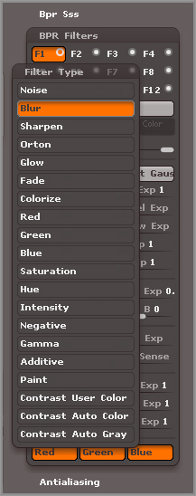
Figure 9-75: Drag from the Depth A slider to the belly button, and drag from the Depth B slider to the character’s fist. This will set the range of depth for the filter.
Figure 9-76: Edit the Blur settings once the depth has been established to create a more realistic depth-of-field–style blur.

Figure 9-77: Add a second filter and adjust the settings to enhance the ambient occlusion shadowing.
You can continue to add filters by clicking the F buttons in the palette. Layering filters opens up a wide number of possibilities for enhancing the look of your ZBrush compositions. Depth is only one of the ways in which filters can be applied. You can also use shadows, ambient occlusion, and subsurface scattering.
Figure 9-77 shows the result.
The best way to understand how the filters work is to experiment with the settings. If you want to apply a filter based on ambient occlusion or subsurface scattering, you have to remember to first activate Ambient Occlusion and Subsurface Scattering in the Render Properties palette. The filter settings are saved with your project, and if you change the view and create another render, the filters will be applied automatically once the render finishes.
ZBrush and Photoshop
ZBrush and Photoshop make a perfect combination for creating amazing images. Many professional concept artists working within the video game and film industries use the two together to quickly produce many variations of character and creature designs within a short amount of time. Regardless of whether your goal is to be a professional designer or to make some cool images, you’ll want to spend some time learning how the two programs can be used together. This section takes you through the process of setting up an image for a specific resolution, rendering in ZBrush, and then exporting passes to Photoshop for further processing. This is not meant to be a comprehensive Photoshop lesson.
If after reading this section you are hungry for more techniques, I recommend reading Scott Spencer’s book ZBrush Creature Design: Creating Dynamic Concept Imagery for Film and Games (Sybex, 2012). In the book Scott includes detailed tutorials covering how he paints his ZBrush creature designs into compelling compositions using many of the techniques he uses at the Weta workshop in New Zealand.
Document Size and Background
If you want to set the document to a specific resolution, you can use the controls in the Document palette.
Figure 9-78: Turn off the Pro button and adjust the Width and Height sliders in the Document palette.
Figure 9-79: Drag from the Back color swatch to the color picker to set the background color for the document.
Render Passes
Whenever you render using BPR, ZBrush separates the render data into passes that can be exported and brought into Photoshop for compositing. The passes ZBrush creates depend on the render options you have activated in the Render palette.
Figure 9-80: Hold your cursor over the icons in the BPR RenderPass subpalette of the Render palette to see a preview of the pass.
Here’s a description of each pass with suggestions on how they can be used in Photoshop:
Creating a Specular Pass
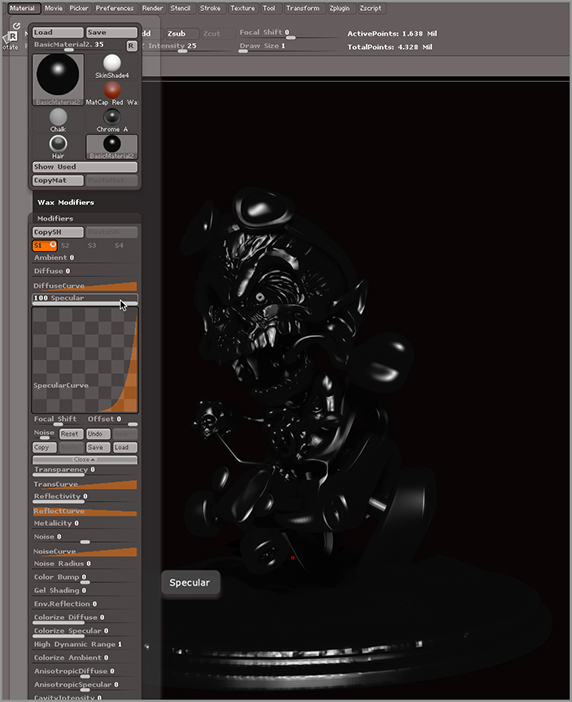
You may notice that the ZBrush does not offer an option for creating a specular pass, but it’s very easy to do this using materials. This technique can be used to create any number of special passes based on material properties:
Figure 9-81: Create a specular pass by rendering a version of the image with a dark, shiny material.
You can experiment with other materials to create additional types of passes. Try using LightCap to create a background panorama and export a render of the model for use as a background pass.
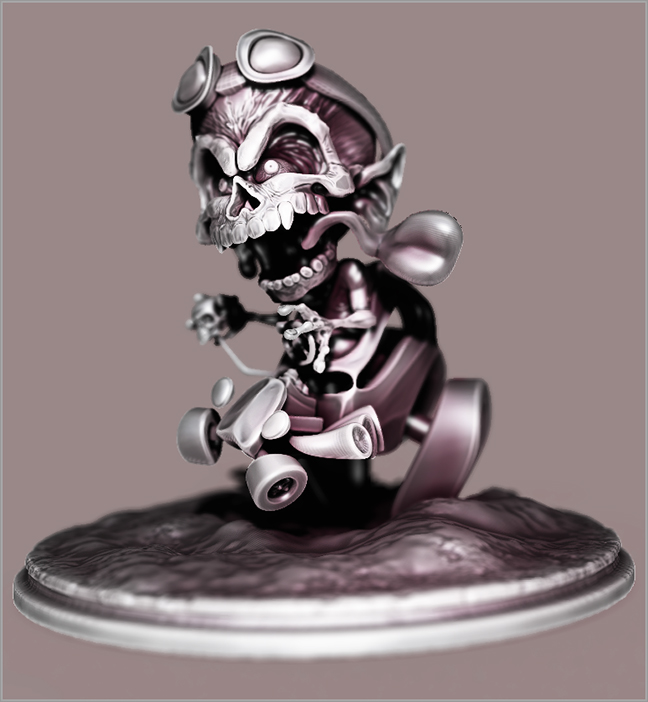
Figure 9-82 shows a composite created from render passes. The Photoshop file Photoshop_composite_BPRPasses.psd is included in the Chapter 9 folder of the DVD. If you have Photoshop, you can open the file and take a look at how the passes are composited together.
Figure 9-82: The exported passes are composited in Photoshop.
Summary
In this chapter you learned how to create hairstyles for your characters using FiberMesh. You learned how to generate a subtool from a FiberMesh preview and how to sculpt FiberMesh using the special hair brushes. You also learned how to set up basic lights in the Light palette and how to create advanced lighting rigs using LightCap. This chapter covered the basics of creating custom materials and how to render using BPR. Finally, you learned how to render passes from ZBrush and composite them in Photoshop.