Chapter 3

Basic Digital Sculpting

Digital sculpting refers to a brush-based approach to creating three-dimensional models on a computer. ZBrush revolutionized the computer game and entertainment industry as well as digital art by introducing its unique digital sculpting technology about 12 years ago. Since then, the older methods of pushing and pulling individual polygon vertices and faces have largely been replaced with digital sculpting. Digital sculpting in ZBrush offers a much more intuitive and artistic way to create models. This is what has made ZBrush so attractive to artists who are less interested in the technical aspects of computer software and more concerned with creating great artwork.

In this chapter, you’ll be introduced to the basics of digital sculpting in ZBrush. We will cover the following topics:

  • Understanding digital clay
  • Loading and saving ZBrush projects
  • Using sculpting brushes
  • Working with dynamic levels of subdivision
  • Using Dynamesh to create a sculpting topology
  • Applying masks to your surface
  • Using parametric 3D objects
  • Using deformations
  • Moving parts using Transpose

Digital Clay

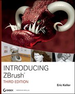
Digital clay is a term affectionately applied to a polygon mesh in ZBrush. This type of mesh is a surface made up of connected polygon faces. Each face shares vertices and edges with neighboring polygon faces (see Figure 3-1). ZBrush allows the polygon faces to be made up of three- or four-sided polygons. These meshes are called digital clay because of the way in which they are shaped by the sculpting brushes. Shaping polygon meshes with the brushes feels so intuitive that it’s a lot like working with clay.

Figure 3-1: Digital clay is a polygon mesh made up of three- or four-sided polygons.

c03f001.tif

Many terms are used interchangeably in ZBrush. Digital clay, polygon mesh, 3D model, and 3D tool all mean pretty much the same thing. You create your models by shaping the surface on the canvas using the sculpting brushes. In order to use the brushes, you must activate Edit mode on the top shelf. Think of Edit mode as Sculpt mode.

The digital clay you use to start your model can be generated a number of different ways. You can use one of the 3D primitive presets or one of the premade models that comes with ZBrush, or you can import a polygon model created in another software package such as modo, Autodesk® 3ds Max®, Cinema 4D, or Autodesk® Maya®. In addition to working with conventional meshes, ZBrush has a number of unique tools that allow you to generate digital clay that can then be sculpted into any shape you wish.

Edit Mode
Edit mode has been known to trip up many new ZBrush users, and it can cause some frustration at first. Often, you’ll find that you accidentally moved out of Edit mode (perhaps by inadvertently pressing the T hotkey), and when you try to sculpt on the surface of a model, a new copy of the model appears instead. And as you continue to draw strokes, more copies of the model appear. To stop this behavior, just remember these simple steps:
1. Press Ctrl+N to clear the canvas.
2. Drag on the canvas to add a copy of the model on the canvas.
3. Press the T hotkey to switch to Edit mode.
4. Continue working on your model.
What is the deal with Edit mode anyway? It makes more sense when you learn that ZBrush began as an innovative illustration tool. The 3D tools are special paintbrushes designed to paint copies of 3D objects on the canvas. Edit mode is used to change the shape of the 3D objects painted on the canvas. While in Edit mode, ZBrush stores the changes made to the 3D tool, keeping an update while you work. When you turn off Edit mode and paint on the canvas, the edited version of the object appears.
As a digital sculptor, you may not be interested in painting pictures with your edited 3D objects. In this case, you’re going to be working in Edit mode most of the time. But it’s important to understand what Edit mode is in case you encounter a type of behavior you don’t understand. When working with ZBrush keep in mind the motto “It isn’t broken; it’s just weird.” The more comfortable you become with ZBrush, the less weird it will seem, but try to be patient at first!

In this chapter, you’ll learn the basics by starting with a simple lump of digital clay that you’ll shape with the sculpting brushes. As you go, you’ll learn new tools and techniques, and in later chapters you’ll learn even more ways to start and sculpt a model.

Using the Sculpting Brushes to Create a Dragon’s Head

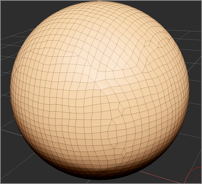
The easiest way to learn your way around ZBrush is to start with a clearly defined goal. In this case, I’ve chosen a dragon’s head as the subject because, well, everyone loves dragons; they are simple, familiar, culturally universal, and fun.

Regardless of how you generate your initial mesh, you will almost always use the sculpting brushes to shape your lump into something more exciting. Once you understand how to use the brushes, all the other elements of the ZBrush interface will make sense. The following demonstrates the fastest and easiest way to start sculpting.

1. Start ZBrush if it’s not open already.
2. Open the Light Box browser and choose the Project tab. Double-click the DefaultSphere.ZPR project (Figure 3-2). If you already have a model loaded on the canvas, ZBrush will ask if you want to save your work. If you do want to save it, click the Save button in the File palette. Once the work has been saved, a sphere will appear on the canvas.
Dragon Reference
A quick search on the Internet will pull up thousands of reference images for dragons. I also recommend the book Dracopedia by William O’Connor (David and Charles Ltd., 2009) as well as Fantasy Art Workshop and Forging Dragons by John Howe (David and Charles Ltd., 2008, 2009). I’ve included some images of real Komodo dragons that I took at the Los Angeles Zoo. Of course, you can also just try sculpting with your own vision; you might not end up with a masterpiece on your first try, but the goal of this chapter is just to have fun playing around in ZBrush so that you get the hang of how it works.
c03uf001.tif

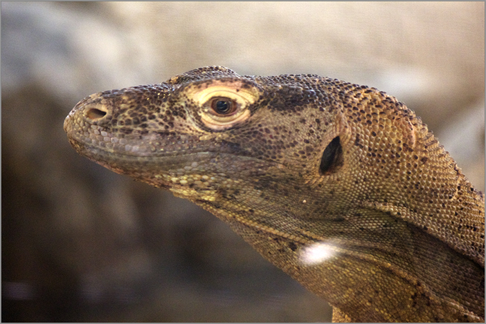
Light Box is a quick and easy browsing interface used to load projects, digital sculptures, textures, and other resources onto the ZBrush canvas. If you are not familiar with using Light Box, consult Chapter 2.

Figure 3-2: Choose the DefaultSphere.ZPR project from the Project section of Light Box.

c03f002.tif
Saving ZBrush Files
When you’re first learning ZBrush, you’ll want to save your files as a ZBrush project. This ensures that the next time you load the project file, you can pick up where you left off and nothing is lost. Later on, you’ll learn how to save individual elements such as 3D tools, textures, brushes, and more. To save a ZBrush project, click the Save As button in the File palette at the top of the screen. The project is saved in the special ZPR format. You can save the project anywhere you like on your hard drive. If you’d like the project to appear in the Project section of Light Box, save it in the ZBrush R3Projects directory. On Windows, this is located in the Program Files directory. On the Mac, it is found in the Applications directory. Be aware that projects save a lot of information, and therefore the files can get quite large. It never hurts to save multiple versions as you work just in case a file gets corrupted. This is true for all software. If your model disappears when you save your project just drag on the canvas and it will reappear; this is an odd display bug which can be a little unnerving especially when you are using the software for the first time!

The DefaultSphere that appears on the canvas is known in ZBrush terminology as the PolySphere. What is a PolySphere? It is a rounded cube and not a typical spherical mesh. A typical spherical mesh has poles—areas on the surface where a large number of triangular faces share a single vertex. These poles can cause pinching and distortion in your sculpt. The advantage of the PolySphere is that it does not have poles, so it is much easier to work with. I use the PolySphere all the time for this reason (see Figure 3-3).

Figure 3-3: The PolySphere on the left is easier to sculpt because it does not have poles like the Sphere3D on the right.

c03f003.tif

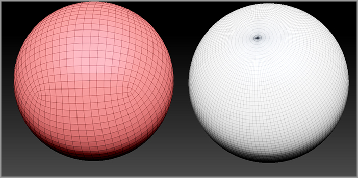
If you’re not sure whether you’re using a PolySphere or a typical spherical mesh, click the PolyF button on the right shelf, and you’ll see the wireframe display on the mesh. The PolySphere should look like the sphere on the left in Figure 3-3 and not the sphere on the right.

3. Move the cursor so that the tip of your sculpting brush appears above the mesh, and you’ll see two red dots above the surface. When you load the DefaultSphere project, symmetry along the x-axis is automatically turned on. This is great because it makes it easy to sculpt a simple head since most heads are symmetrical along the x-axis.

You can turn symmetry on or off by pressing the X hotkey. For now let’s leave it on. Later in this chapter you’ll learn about more advanced symmetry options. If you run into a situation where symmetry has been activated but you see only a single dot, you may need to rotate the model until you’re facing the correct axis, at which point the two dots should appear. Basic navigation is covered in Chapter 2, “Understanding the ZBrush Interface.”

When I start a sculpt, I like to use the BasicMaterial2 shader, which you will find in the material fly-out library on the left shelf. Simply open the library by clicking the Material icon, and choose BasicMaterial2. How to use the material library is covered in Chapter 2. The BasicMaterial2 shader is not as exciting as some of the others, but it gives you the best sense of the shape of your sculpt as you work. It’s good to change materials occasionally while you work.

4. Now let’s start shaping the head using the Move brush. Open the sculpting brush fly-out library in the upper left of the ZBrush canvas and find the Move brush.
Searching the Brush Library
The brush fly-out library contains a large number of brush presets. If you know the name of the brush you are looking for, you can speed up your search by typing the first letter of the brush’s name while the fly-out is open. For example, if you are looking for the Move brush, open the sculpting brush library and then type M. You’ll see all the brush icons become grayed out except those that start with M. This makes it easier to spot the Move brush.
You’ll also notice that each brush has a letter in the upper-left corner of its icon. If you type this letter while the brush fly-out library is open, ZBrush will set the brush preset as the currently active brush. For example, typing M and then B while the brush fly-out library is open will automatically set the current brush to the Move brush preset. Typing C and then B while the brush fly-out library is open sets the current brush to the ClayBuildup brush preset.

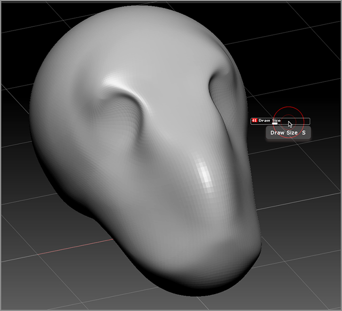
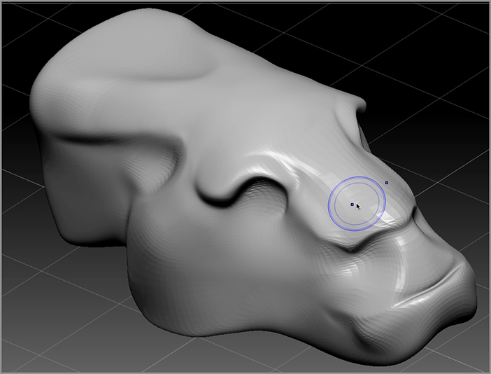
Figure 3-4: Use the Move brush to start shaping the PolySphere into something that looks like a dragon’s head.

c03f004.tif
5. Let’s start by getting a general sense of the dragon head shape. To do this we’ll push and pull on the PolySphere using a large brush size. Increase the brush size slider until there is a large red circle for the brush tip; then drag on the surface of the PolySphere. Notice that changes are made to both sides of the PolySphere at the same time.
6. Push, pull, drag, and shape until you have something slightly dragon-like (see Figure 3-4). Pull out the front to create a snout, and then push in areas for the eyes. Don’t be afraid to adjust your draw size while you work. In fact, if you hold the S hotkey, the Brush Size slider will appear on the canvas, saving you a trip to the top shelf.
Tips on Using the Move Brush
  • Increase the Z intensity if you want to have a stronger influence on the surface. Sometimes I like to have a strong intensity with a small brush size for precise changes and a low Z intensity with a large brush size to make more general changes.
  • Hold the Alt key while dragging on the surface to move the surface along the surface normal (surface normals are defined in Chapter 1, “Digital Art Basics”). Drag left while holding the Alt key to push in; drag right while holding the Alt key to push out.
  • Change the Focal Shift slider to adjust the brush falloff. A low focal shift will give the brush a hard edge; a high focal shift will create a smooth falloff.
  • Other variations of the Move brush are available in both the sculpting brush library and the Brush/Move section of Light Box. These variations can create some really interesting effects.
7. Open the sculpting brush library and select the Move Elastic brush. Try using the Move Elastic brush while shaping your head model. This brush has a very rubbery feel to it (Figure 3-5). I find that by moving the surface back and forth very gently, I can create some interesting shapes in the surface. It does take a little practice.

The Move Elastic brush works best on meshes with 24,000 polygons or less. If you use it on a dense mesh (meaning a mesh with a lot of polygons), it will slow down performance significantly. This is because ZBrush is updating the model as you work, which takes some calculations. As you work through the examples in this book, you’ll learn about other Move brush variations, such as the Move Topological and Move Parts brushes. Switching brushes while working is a great way to explore new ideas and forms.

8. Try the Nudge brush, which is similar to the Move brush but with a slightly more precise feel. Once you have something you like, click the Save button in the File palette and save the model to your local disk using a unique name such as dragon_01.ZPR. The basic dragon’s head is shown in Figure 3-6.

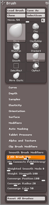
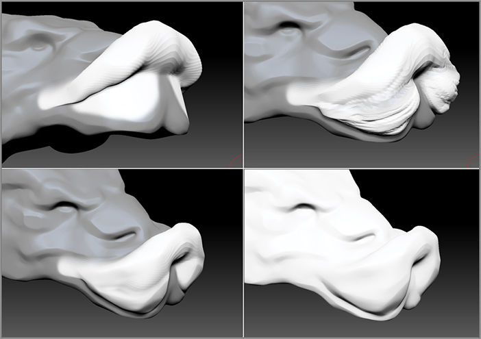
Figure 3-5: Try using the Move Elastic brush to shape the head; compare how the surface reacts to the Move Elastic brush versus the Move brush.

c03f005.tif

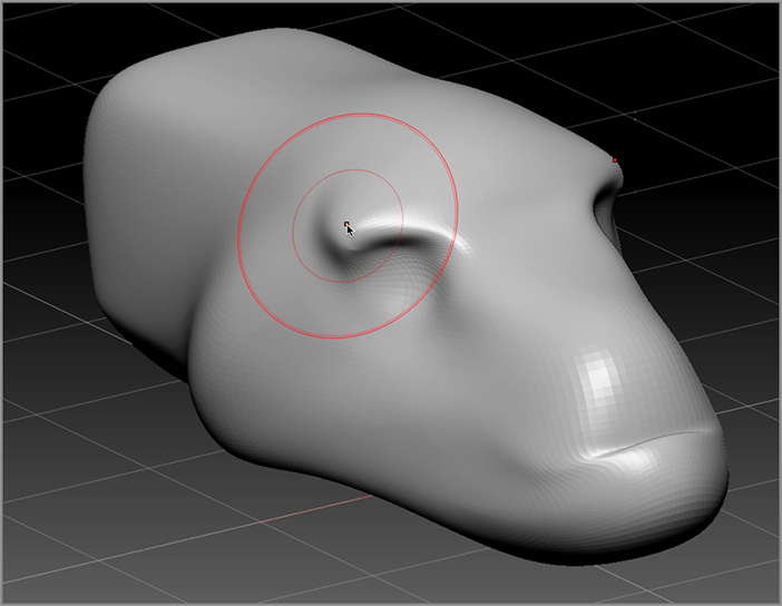
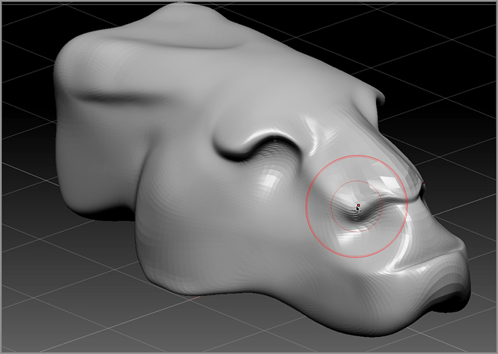
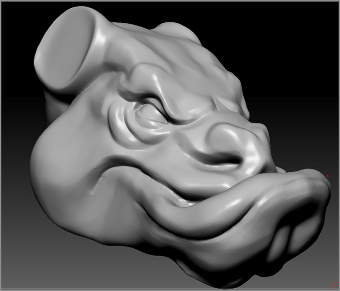
Figure 3-6: A basic dragon’s head is shaped using the Move, Move Elastic, and Nudge brushes.

c03f006.tif

Using the Smooth Brush

As you shape your model, you’ll no doubt get some stretching in the surface. One way to deal with this is to use the Smooth brush. Hold down the Shift key and drag over the model. The Smooth brush evens out the surface and reduces the stretching.

The shape of the surface seems to shrink and melt away as you brush over it while holding down the Shift key. The Smooth brush averages the distance between the vertices on the surface. If the changes are too extreme, you can lower the Z intensity of the Smooth brush.

1. Increase the draw size of the brush and smooth the parts of the surface that appear stretched. The smooth effect is stronger with a larger brush size because a larger area of the surface is being sampled as you brush. You can quickly call up the brush size controls by holding the spacebar while the brush is over the canvas.
2. Hold down the Shift key and adjust the Z intensity.
3. Paint over the stretched areas of the surface while holding the Shift key to smooth the surface. Note that the brush icon turns blue when you are holding the Shift key, indicating that you are in Smooth mode.
4. Release the Shift key, and pull on the model to continue shaping with the Move brush.
5. Sometimes gently tapping the surface using the digital tablet is the best approach; it can keep you from obliterating your work. Digital clay is flexible enough that you can test a large number of ideas while you work. When I start sculpting a model from a PolySphere, I spend a lot of time using just the Move and Smooth brushes while focusing on the form (see Figure 3-7).

Figure 3-7: Alternate using the Move and Smooth brushes while creating the basic shape of the dragon’s head.

c03f007.tif
6. Don’t forget to save the file frequently as you work! Click the Save As button in the File menu to save the ZBrush project.
Tips on Using the Smooth Brush
  • The Z intensity of the Smooth brush is independent of the current brush, meaning that the value changes when you switch to the Smooth brush. ZBrush remembers the Z intensity of the Smooth brush even when you release the Shift key and switch to another brush. This is also true of the Focal Shift setting but not Draw Size.
  • A high Z intensity, such as the default setting of 100, can quickly obliterate details sculpted into the mesh. It’s good practice to set the Z intensity of the Smooth brush to somewhere between 20 and 40 while working.
  • A number of other smoothing brushes are available in the brush fly-out library and in the Brush section of Light Box. If you choose one of these brushes, you’ll get a message letting you know that the chosen smoothing brush will be active only while you are holding down the Shift key. The other smoothing brushes have unique properties that will make more sense once you’ve learned more about ZBrush.
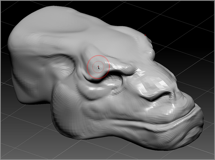
  • The Brush palette contains a set of controls that are dedicated to the Smooth brush. These are found toward the bottom in the Smooth Brush Modifiers subpalette, as shown in the following image. This palette will be explained in more detail in Chapter 7, “Advanced Brush Techniques.” For now it is useful to know that the Alt Brush Size slider adjusts the size of the Smooth brush. This value is a multiplier for the Draw Size setting. When you set Alt Brush Size to 2, every time you hold down the Shift key, the draw size of the Smooth brush will be twice the draw size of the current brush. A setting of 10 will make the Smooth brush 10 times the current brush size.
c03uf002.tif

Defining Forms with the Standard and Clay Brushes

Once you have the basic dragon’s head form established, you can start building basic detail using the standard band clay sculpting brushes. Of course, you can use the sculpting brushes in any order you wish and switch between the brushes at any time. I find it’s easier to introduce the sculpting process to new students by working with just a few brushes at a time. Focus on large bony forms for now; at this point you should not worry about little details like scales and wrinkles.

The Standard brush causes the points of the mesh to be pushed outward based on an average of their normal direction. If you hold the Alt key while dragging across the surface, the brush is reversed so that the mesh gets pushed inward.

The Clay brush also causes the surface to be raised, but it generally fills in the recessed areas of the surface first, making the brush feel as though you’re pressing clay into the surface. It’s important to understand that none of the sculpting brushes actually add or remove points from the surface; they just move the existing points around based on their own specific algorithms.

Just like with the other brushes, the Z intensity increases the amount of influence the brush has on the surface, and the Focal Shift adjusts the falloff.

1. Open the sculpting brush library and press the S key and then the T key to select the Standard brush. Reduce the size of the brush so the changes you make aren’t too extreme.

Figure 3-8: Use the Standard and Clay brushes to further define the forms of the head.

c03f008.tif
2. Brush over the surface of your shaped PolySphere to sculpt the bony forms above the eye for the dragon. Try making nostrils as well.
3. Experiment with adjusting the Z intensity, Draw Size, and Focal Shift while you work, and see what kind of shapes you can build into the head.
4. Hold the Alt key to dig into the surface. Remember to constantly rotate and examine the model as you work. Try to shape the whole surface, and don’t get too caught up in overworking a single area.
5. Open the sculpting brush library and chose the Clay brush (press the C key and then the L key to select the Clay brush). Brush over the surface, and compare how the brush behaves to the Standard and Move brushes (see Figure 3-8).
6. Don’t forget that any time you want to smooth the details on the surface, just press the Shift key.
7. Save your model when you have something that you like.
Tips on Using the Clay Brush
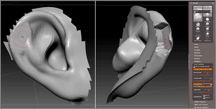
  • Sometimes the Clay brush can cause problems when you’re working on thin surfaces such as ears. While the part of the surface that is facing you may appear fine, the reverse side may become stretched, as shown in the following image below. To fix this, open the Brush palette, click the Auto Masking button, and activate the Backface Mask button. This is off by default simply because it may slow down performance on high-density meshes.
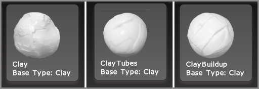
  • There are many variations of the Clay brush. Try using the Clay Tubes and Clay Buildup brushes, and see how they behave when working on your model.
  • Just like the Standard brush, the Clay brush will dig into the surface when you hold the Alt key.
c03uf003.tif
Brush Algorithms
By now you’ve gotten a taste of the basics when working with sculpting brushes, but let’s take a moment to contemplate the nature of these amazing tools.
Each sculpting brush is based on an algorithm, which is simply a recipe that tells ZBrush how a particular brush will affect the surface of the digital clay. As you brush across the surface of the model, imagine that a short conversation takes places between the brush tip and the surface of the clay. This conversation is known as sampling. While sampling, the brush determines the number of polygons within the Draw Size, the normal direction of the polygons, whether the surface is masked or painted (topics we’ll discuss in detail a bit later), and other important bits of information. At the same time, ZBrush is paying attention to the algorithm of the current brush and how it moves the points on the surface. It’s also keeping track of the brush’s Z intensity, Draw Size, Focal Shift, how the brush is oriented relative to the surface, and how the brush should react to the amount of pressure you are applying to your digital tablet.
You don’t need to have a computer science degree to understand how to work with the algorithms. It’s enough to know that the Standard brush moves the points of the surface outward based on an average of the normal direction of the surface. The algorithm of the Inflate brush, on the other hand, pushes the points out based on the normal direction of each point. The result is that the Standard brush and the Inflate brush behave in different ways when sculpting the surface.
ZBrush gives you a wide variety of controls that allow you to customize your brushes and even create your own variations. Most of these controls are found in the Brush palette. Many of these controls are discussed in more detail in Chapter 7. If you’re dying to know how to make your own brushes, feel free to skip ahead to that chapter. For now, you should understand that the brush presets are based on a few base types. You can find out which base type the brush uses by holding your pointer over the icon in the Brush palette. At the bottom of the preview you’ll see a little note that indicates the base type for the brush. Notice that the Clay, Clay Tubes, Clay Buildup, and Polish brushes all use the Clay base type. A description of the base types is found in Chapter 7 of this book.
c03uf004.tif

Working with Dynamic Levels of Subdivision

You may have seen many highly detailed ZBrush models on the Internet or in movies or video games. How do artists get all this detail into their ZBrush model? It’s done by subdividing the mesh, which means that the number of polygons that make up the surface is multiplied, giving you more polygons to work with so the brushes can easily add more detail.

The great thing about ZBrush is that when you add more polygons to the surface by subdividing, you can easily go back to a lower number of polygons. In fact, you can go back and forth between a version of the model that has few polygons and less detail and a version of the model that has many polygons and a lot of detail. You can do this as often as you like while you shape your model. So at lower levels of subdivision (known as an SDiv level) you can shape the overall form, kind of like what you’ve already done with your dragon’s head. Then you can subdivide, add more details like the nostrils and eye sockets, then subdivide a few more times to add scales and curling lips, and so on until the model is made up of millions of polygons and loads of realistic detail. But you can, at any time, go back to the lower SDiv level, make changes to the overall form, and ZBrush will remember and retain all of those crazy details, so that when you switch back to a high SDiv level, you still have your scales and wrinkles and curling dragon lips. This gives you an amazing amount of control as an artist, and it’s something you really can’t do in traditional media such as clay.

In this next section, we’ll take the dragon’s head you have been working with and add a few levels of subdivision to show how to use this to your advantage.

1. Use the File menu to open the most recent version of your dragon’s head model.
2. Make sure the Edit button on the top shelf is on, indicating that you are in Edit mode.
3. Expand the Geometry subpalette of the Tool palette, and take a look at the SDiv slider.

The default PolySphere you used to start your model already has three SDiv levels, and you can easily add even more.

4. Drag the SDiv slider to the left to move to a lower SDiv level. You’ll see that the model looks a little chunkier at lower levels of subdivision.
5. Turn on the PolyF button on the left shelf so you can see the wireframe. At lower SDiv levels there are fewer polygons and they appear larger (left image in Figure 3-9).
6. Move the SDiv slider all the way up to level 3. Click the Divide button in the Geometry subpalette to subdivide the model. This subdivides the model, which means that the number of polygons at SDiv 3 are multiplied by 4 (right image in Figure 3-9).
7. Look at the Total Points listed on the top shelf; the model now has 98,306 points. The SDiv slider now goes from 1 to 4, the highest level of subdivision.

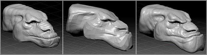
Figure 3-9: Low subdivision levels have fewer polygons and less detail (left image). Add a fourth level of subdivision to increase the number of polygons available for sculpting (right image).

c03f009.tif
8. Click the Divide button again; now the model has five SDiv levels, and at SDiv 5 the total number of points is 393,218.
9. Experiment with moving to different SDiv levels, and make changes with the Move, Standard, Smooth, and Clay brushes. See how this affects details at higher subdivision levels. It’s also easy to make major changes to the form at lower SDiv levels without destroying the details you sculpt at the higher levels (see Figure 3-10).

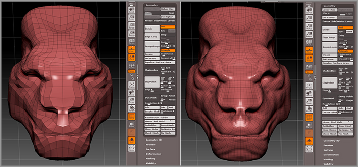
Figure 3-10: You can switch between higher and lower subdivision levels as you work to sculpt detail or make major changes to the form.

c03f010.tif
10. When you feel like you understand SDiv levels, use the File menu to save your model.
Tips on Working with Subdivision Levels
  • To add a level of subdivision, you must have the slider set to the highest SDiv level; otherwise, you’ll get a warning message.
  • You can delete the levels of subdivision by clicking the Delete Lower or Delete Higher Levels Of Subdivision button. Doing this will automatically renumber the SDiv levels, so if you are at level 3 and you delete lower levels of subdivision, what was level 3 now becomes level 1.
  • When you subdivide the model, the surface will be smoothed automatically. If you want to keep the hard-edge look of the model when you subdivide, turn off the Smt button next to the Divide button in the Geometry subpalette.
  • You can add a lower level of subdivision by setting the SDiv slider to the lowest level and clicking the Reconstruct Lower Subdivision button found in the Geometry subpalette of the Tool palette. Use this with caution because it can sometimes affect detail at the highest SDiv level. When in doubt, save the file before clicking this button! In some cases this won’t work. If the mesh has triangles, ZBrush will not be able to add a lower level of subdivision.
  • You can subdivide sections of a mesh if parts become overly stretched. To do this, move the SDiv slider to the lowest SDiv level and click the Equalize Surface button in the Geometry subpalette. You can also explicitly subdivide a section of the surface using masking. This will be discussed later in the chapter in the section on masks.
Topology
In the world of digital 3D modeling, the term topology refers to how the polygon faces that make up a 3D mesh are arranged on the surface. There are different methods for creating topology. Some topologies are better suited for digital sculpting than others. To create the best possible motion for the creatures and characters they animate, animators working in 3D software have special requirements for the topology of the models they use. If you intend to create models for use in video games or in animation, you will need to become very conscious of topology. ZBrush even has tools that allow you to re-create the topology of a model after you have sculpted it.
These days it has become common practice to sculpt the model first using a sculpting-friendly topology. Then, once the model has been approved for animation or printing, you can “retopologize” the surface to create an animation-friendly or printer-friendly topology. The original model is always available as a source for generating any kind of topology you need.
The following image shows the same model. The version on the left has an animation-friendly topology; notice how the edges of the polygons form loops around the mouth and eyes. This kind of edge flow deforms well when animating facial expressions. The version on the right has an even distribution of polygons that are all about the same size. This kind of topology works well when sculpting shapes into the mesh. You can create, sculpt, and use both types of topologies in ZBrush. Which topology you use depends on what you want to do with the model and your preference as an artist. The makers of ZBrush are not interested in restricting you to one workflow over another. They are more interested in giving you as much creative freedom as you need to achieve your goals. And, of course, ZBrush allows you many ways to move between animation and sculpting topologies; you’ll learn about these techniques throughout this book. The next section covers how to convert a model into a sculpting topology using Dynamesh.
c03uf005.tif

Creating a Sculpting Topology with Dynamesh

As you work over the surface with the sculpting brushes, the surface may appear stretched as the polygons of the mesh are pulled. This happens especially when you pull out the mouth of a dragon or try to make ears or horns. The Smooth brush can help alleviate this, but it can only take you so far, and too much smoothing results in kind of an amorphous blob. Subdividing the model also helps eliminate the stretching, but as you sculpt against the “grain” of the polygon, the surface still can look stretched unless you work on a mesh that has millions of polygons.

To eliminate these types of problems Pixologic has introduced a new technology known as Dynamesh. Dynamesh creates a sculpting-friendly topology dynamically as you work whenever you need it. Dynamesh is a special mode that, when activated, rebuilds the topology of your mesh to make it easier to sculpt. Let’s try it out on the dragon’s head you have been working on.

Z-speak
The folks at Pixologic love inventing new terms almost as much as inventing new tools. Dynamesh, ZSketch, ShadowBox, and FiberMesh are just a few of the terms that will soon become a part of your vocabulary as you delve deeper into ZBrush. As you become fluent in Z-speak, you’ll find it’s a handy way to connect and communicate with other ZBrush users; however, you may get some strange looks from “regular” 3D artists. But who wants to be regular anyway?

Using Dynamesh on the Dragon’s Head Model

1. Open the most recent version of the dragon’s head model. Turn on the PolyF button on the left side of the canvas so you can see how the polygons on the surface are arranged; this will also make it clear which parts of the model may be badly stretched.
2. Set the SDiv to the highest level, and click the Delete Lower SDiv Level button to remove the lower SDiv levels. The SDiv slider will become grayed out, indicating that there are no longer any lower levels of subdivision.
3. Expand the Tool palette to the Geometry tab. Turn on the Dynamesh button. After a few seconds you’ll see the model update (see Figure 3-11). The shape should look about the same, but notice that now, instead of stretched polygons of various sizes, the surface is made up of many square-shaped polygons plus a few small triangles. This type of topology is much easier to sculpt.

Figure 3-11: Dynamesh instantly retopologizes the surface of the model so it is easier to sculpt. The result is a surface made up of evenly distributed squares and triangles.

c03f011.tif
4. You may see stretch marks, but this is a result of the original shape being projected onto the new Dynamesh. Hold down the Shift key and drag over the stretch marks to remove them with the Smooth brush.

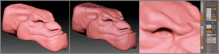
If you feel like you don’t have enough polygons (or maybe too many), you can easily change the number dynamically (hence the term Dynamesh) by changing the Resolution slider below the Dynamesh button. The surface updates automatically. Lower values mean fewer and larger polygons.

5. Now to see how powerful Dynamesh is, it’s time to go a little crazy. Make sure the Dynamesh button is still on while you work, and use the Move brush to push and pull, to drag out the parts of the dragon head to a crazy extreme, and to try pulling out some horns.
6. The stretch marks will appear again, but don’t worry! Press Shift+A (or hold down the Ctrl key and drag on a blank part of the canvas and release). Dynamesh re-creates each time you do this, so you can work very quickly and eliminate the stretch marks instantly (see Figure 3-12).

Figure 3-12: Pull some horns out of the head using the Move brush. Hold down the Ctrl key and drag on the canvas to instantly retopologize the surface, eliminating stretching.

c03f012.tif
7. The power of Dynamesh is that it frees you from worrying about stretched polygons while you work. Turn off the PolyF button and experiment using the sculpting brushes to shape the horn. Every time you feel the surface is becoming too stretched, just Ctrl+drag on the canvas to activate Dynamesh, and then use the Smooth brush to clean up the surface.
8. Try adding tendrils to the jaw or even some teeth popping out of the mouth using the Snakehook brush. Repeat the process of pulling geometry with the Move brush, updating the surface with Dynamesh, and then smoothing the surface with the Smooth brush.

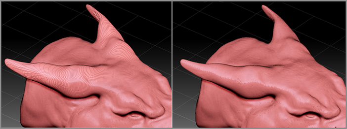
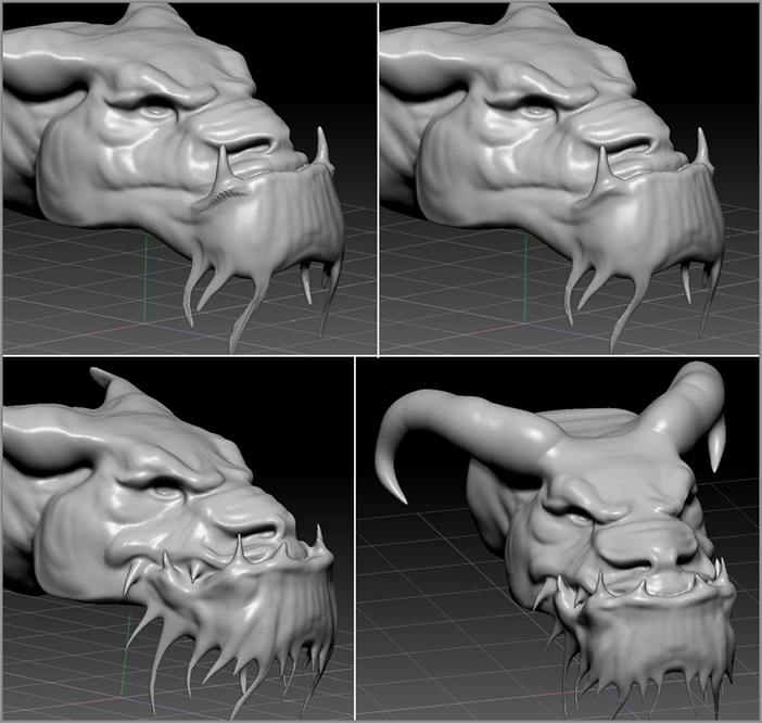
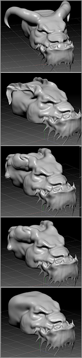
Figure 3-13 shows the process I went through in shaping my dragon’s head. Throughout this process I’m still experimenting with ideas, adjusting the anatomy and the personality of the dragon as I work. You’ll find that this workflow turns ZBrush into a great tool for sketching out ideas.

Figure 3-13: Using Dynamesh to update the topology of the surface as you work, you can easily pull clay out from the geometry of the head.

c03f013.tif

Editing Your Design

Using Dynamesh, you can feel free to experiment while sculpting. You’re never stuck with what you make, and you can always easily make radical changes and then remove them at will if you change your mind. For example, I’ve decided that the horns on my dragon make him look too much like a ram. I want to get rid of them without starting over. Using the Dynamesh workflow, I can simply squish the horns back into the head and try something different.

Figure 3-14: The Resolution slider is found below the Dynamesh button in the Geometry subpalette of the Tool palette.

c03f014.eps

To make this easier you can use the Move Topological brush to push the horns back into the head. The Move Topological brush samples the surface as you work to determine which parts of the mesh are connected. You can use this brush to move the horns close to the head without affecting the head itself. The brush may feel a little sticky because the mesh is fairly dense. Generally, it’s best to use the brush on a lower-density mesh.

Currently, my mesh has more than 150,000 points, but I deleted the lower levels of subdivision. So how can you create a mesh that’s a little easier to work with? You can change the resolution of Dynamesh so there are fewer polygons to work with, making it easier to edit the overall form:

1. In the Geometry palette, make sure the Dynamesh button is still on. It should be a bright color. Set the Resolution slider to 64 and Ctrl+drag on the canvas (see Figure 3-14). The surface should update. If it does not, touch the surface with the brush to make a small change and then Ctrl+drag on the canvas again. Sometimes Dynamesh requires that you make a small change before updating.
2. The mesh should now be a lower resolution; after I did this, the number of points in my surface moved from 190,000 down to 49,800. In ZBrush terms, that’s a medium-level resolution, which should work great with the Move Topological brush.

How did I come up with a setting of 64? I came to this value through experimentation. If the resolution you choose is not low or high enough for what you want, you can undo (Ctrl+Z), set a new value, and then try again until you get a resolution you like. The scale of the object will affect the resolution. A very small object requires a higher-resolution setting to get a decent number of polygons; a very large object can become extremely dense when you “dynamesh” at even a low-resolution setting.

Figure 3-15: Use the Move Topological and Inflate brushes to move the horns back toward the surface. Activate Dynamesh again, and the horns are fused to the surface. With a little cleanup, the horns are completely gone.

c03f015.tif
3. Select the Move Topological brush and move the horns toward the head. No need to be overly careful; just drag them back as if the head was made of clay.
4. Use the Smooth brush as you work to smooth the surface.
5. Once the horns are close to the head, use the Inflate brush to pump up the area so that the horn and head geometry overlap.
6. Now Ctrl+drag on the canvas to “re-dynamesh.” The horns are fused with the surface.
7. Use the Smooth, Move, and Clay brushes to clean up the area. Then Ctrl+drag on the surface to re-dynamesh as you go. Before you know it, those goofy horns are just a fading memory (see Figure 3-15).
8 Set the Resolution slider below the Dynamesh button back to 128 and Ctrl+drag on the canvas. Now you have a high resolution again, and you can continue to work.

I decided to get rid of the teeth and the tendrils using the same techniques (see Figure 3-16). You can continually model and shape with Dynamesh as you explore ideas.

Figure 3-16: The tendrils on the chin have been removed by simply pushing them back into the surface and re-dynameshing the surface.

c03f016.tif

Refining the Surface with Polish Brushes

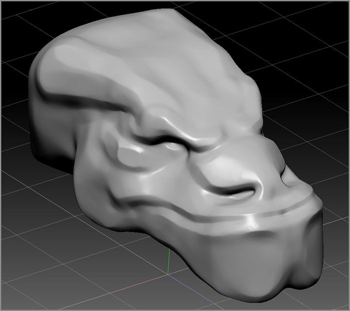
As you sculpt your digital clay, you may notice that the shape can become quite lumpy. You can reduce the lumpiness of the form as well as bring definition to the planes of the dragon’s head using the polish brushes.

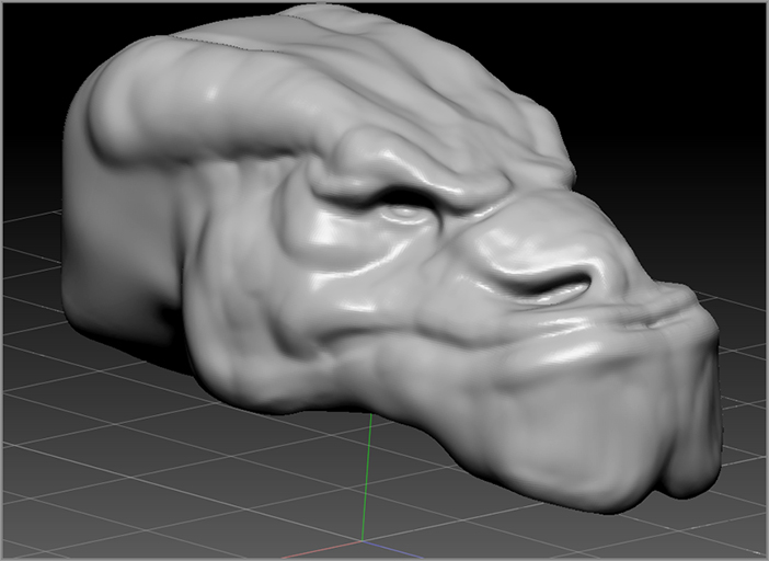
Figure 3-17: Use the hPolish brush to refine the forms of the dragon’s head.

c03f017.tif
1. Open the most recent version of your dragon’s head project. Make sure that the dragon’s head is on the canvas and that Edit mode is active.
2. Open the sculpting brush library and press the H key on your keyboard. This switches the current brush to the hPolish (hard polish) brush (the only brush preset that starts with the letter h).
3. Use the brush to start defining the forms of the head; think about the bone structure of the dragon as you work. Again, no need to worry about fine details such as scales and wrinkles; at this point you just want to establish the final overall form of the head (see Figure 3-17).
Tips on Using Polish Brushes
  • Just as with the other sculpting brushes I tend to smooth as I work by alternating holding and releasing the Shift key.
  • The hPolish brush can be used to create sharp angles when it is used to polish adjacent forms.
  • Several variations of the Polish brush are available in the brush library, including nPolish and sPolish, and even more in the Brush section of Light Box.
  • The hPolish brush presses down the surface; if you want to use the brush to build out the surface, hold down the Alt key.
  • The Trim Dynamic brush can also be used to refine the surface. It is similar to the hPolish brush but with some subtle differences. I use both while I am working. The Trim Dynamic brush is good at flattening sharp edges.
  • If you activate the Polish option to the right of the Dynamesh button in the Geometry subpalette of the Tool palette, then every time you re-dynamesh the surface, it will add an overall polish to the surface. This can eliminate lumps as well as accentuate the contours of your design. It also keeps the dynameshed surface from becoming too “soft.”

Masking

Masking protects a specified part of the mesh as you make changes. Masks give you more precise control over the mesh, and there are a number of ways to create masks. Masks are created using the Masking Pen brush. This brush is activated when you hold down the Ctrl key while the Draw button is active on the top shelf.

Using masks you can increase the level of precision you have when using the sculpting brushes. Also, a number of processes in ZBrush require that parts of the surface be masked in order to work properly. Let’s start by discussing the basics of creating masks.

Using Sculpting Brushes and Hotkeys
When you are using the sculpting brushes together with hotkeys, you can start to get tangled fingers and a little mixed up as to what hotkey does what. It does take some practice. Keep these general rules in mind when learning ZBrush hotkeys:
  • Hold Shift to activate smoothing brushes.
  • Hold Ctrl to activate masking function.
  • Hold the Alt button to reverse the brush; this creates the opposite action in the brush. If the brush normally pushes out, then it will push in when you hold the Alt key. If the brush normally smoothes, then the Alt key will make it sharpen, and if the brush normally masks, holding Alt will make it unmask.
By the end of the chapter I’ll add a few more rules to this list. But first you should try using these options as you practice in the next few exercises.

Mask Controls

In this exercise you’ll use masking to control which parts of the dragon’s head model can be edited with the brushes.

1. Load the most recent version of your dragon’s head model into ZBrush. We’re going to look at how masks can be used to modify the lower lip of the dragon.
2. Open the sculpting brush fly-out library on the left shelf and press S and then T to choose the Standard brush.
3. Make sure symmetry is activated along the x-axis. If you rotate the view of the head to the top, front, or bottom, you should see two red dots as you hold the brush tip over the mesh. This means symmetry is on. If you don’t see two dots, press the X hotkey to turn symmetry on.
4. Open the Material library on the left shelf and choose the SkinShade4 material (see Figure 3-18). This material will make it easier to see the masks you paint on the surface.

Figure 3-18: Open the Material library on the left shelf and select the SkinShade4 material.

c03f018.tif
5. Hold down the Ctrl key and brush along the lip of the dragon. The masked area appears as a dark gray color on the surface (see the left image in Figure 3-19).
6. Release the Ctrl key and try painting on the dark area with the sculpting brush. Nothing happens. Try painting on the white areas, and you’ll see that the surface is raised under the brush just as you would expect using the Standard brush. The darker areas are protected from the brush (see right image in Figure 3-19).

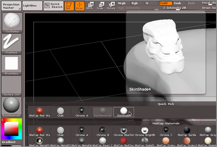
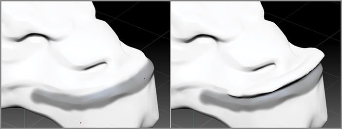
Figure 3-19: The mask on the lower lip of the dragon protects the surface from changes made with the sculpting brush.

c03f019.tif

When you press and hold the Ctrl key while the Draw button is on in the top shelf, you activate the MaskPen brush. As you hold down the Ctrl key, note that the brush icon on the left shelf displays the MaskPen brush (see Figure 3-20).

Figure 3-20: While you hold down the Ctrl key, the brush switches to the MaskPen brush.

c03f020.tif

Of course, the changes I just made on the surface are not what I want at all; in fact, I want the opposite. I want to pull out the lip to make room for some giant teeth jutting out of the lower jaw. So I need to undo the last few strokes, invert the mask, and then edit the lip while the rest of the head is masked.

7. If you’ve made similar changes on your dragon, press Ctrl+Z to undo those brush strokes. You can undo several times by repeatedly pressing Ctrl+Z. Return the dragon to the point before you sculpted the unmasked areas. Try not to undo painting the mask though.
8. You should end up with a mask painted on the lip. Now you’ll invert the mask so everything is masked except the lip. To do this you can either press Ctrl+I or hold Ctrl and tap on a blank part of the canvas. Either action inverts the mask painted on the surface. Now it should appear light colored while the rest of the dragon appears dark gray (see the left image in Figure 3-21).
9. Before sculpting the lower lip, you can blur the edges of the mask, which can help make the brushstrokes at the edge of the mask a little smoother. To do this, hold the Ctrl key and tap or click the masked part of the surface. The edges of the mask should look blurred. Each time you repeat this action, it will blur the mask a little more (see the right image in Figure 3-21).

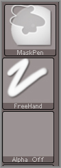
Figure 3-21: The mask is inverted (left image); then the edges of the mask are blurred (right image).

c03f021.tif
10. Now open the Brush palette and switch to the Move brush (press the M key and then the V key while the brush library is open). Use the Move brush to pull the lip up and out a little, as shown in the upper left of Figure 3-22.

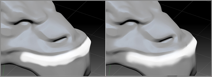
Figure 3-22 shows how I used the Move, Inflate, Smooth, and hPolish brushes to form an exaggerated underbite in the dragon.

Figure 3-22: The Move, Inflate, Smooth, and hPolish brushes are used to pull out the lower lip of the dragon.

c03f022.tif

Editing the Mask

Masks are useful and extremely flexible. You can edit the mask using the masking brushes in order to precisely isolate areas for further sculpting, all while protecting the areas you don’t want the brushes to affect. In this section, you’ll use more masking features to edit the mask painted on the dragon’s lip.

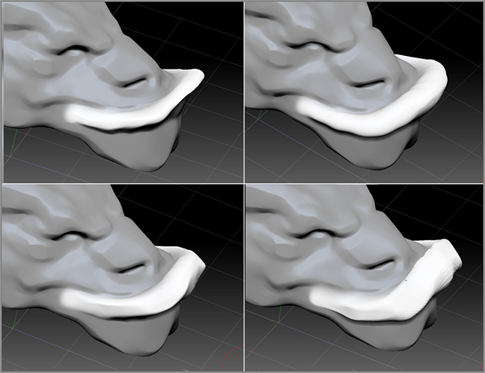
The big problem with the way the lip looks on my dragon is that it has too much of an overhang. I’m going to use the mask pen to expand the current mask and then use the ClayBuildup brush to create flesh below the lip so that it looks like the lip is stretched over large teeth coming out of the jaw. Here’s how you can accomplish the same thing on your model:

1. Start by erasing part of the mask below the lower lip. Hold Ctrl+Alt at the same time and paint two oval areas below the lip. (Remember that the Ctrl key masks and the Alt key reverses, so by holding Ctrl and Alt together you create a reverse mask, which erases the mask wherever you paint. (See the top-left image in Figure 3-23.)
2. Now open the Sculpting Brush library on the left shelf and select the ClayBuildup brush (the hotkey for this brush is C and then B while the brush library is open). Use the brush to fill in the area below the lip, as shown in the upper right of Figure 3-23.
3. Use the Smooth and hPolish brushes to clean up the sculpted area (see the lower-left image in Figure 3-23).

At this point the surface is getting stretched, so you can dynamesh the surface to remove the stretching. To do this you need to first clear the mask and then dynamesh. Both actions use the Ctrl+drag gesture.

4. Hold Ctrl, drag on a blank part of the canvas, and release. This clears the mask.
5. Hold Ctrl, drag on a blank part of the canvas, and release again. It’s the same action as in step 4, but this time, since Dynamesh is still active, the surface will be retopologized instantly (see the lower right in Figure 3-23).

Figure 3-23: The MaskPen brush is used as an eraser to expand the mask (upper left). The ClayBuildup brush is used to fill in the area below the lip (upper right). The unmasked portion is refined using the Smooth and hPolish brushes (lower left). The surface is unmasked and dynameshed to remove stretching.

c03f023.tif

By using similar techniques you can continue to shape the dragon’s head to get it ready for adding teeth and eyeballs. Figure 3-24 shows some of the steps I used to refine the surface. In addition to using the Standard, Clay Tubes, Smooth, Move, and hPolish brushes, I used the DamStandard brush (found in the brush library when you press the D key and then the S key) to create fine lines. Try this brush to start sketching lines on the surface to help separate the features. You’ll find this brush absolutely indispensible for sculpting. I also frequently re-dynamesh the surface with the Polish option activated in the Geometry palette; this keeps the surface smooth and the edges refined. Make sure you save your project if you come up with something you like!

Figure 3-24: Using the MaskPen, Standard, Smooth, Inflate, Move, DamStandard, and hPolish brushes, the features are shaped and refined. Dynamesh is applied with the Polish feature enabled to keep the surface smooth and edges sharp.

c03f024.tif
Basic Masking Hotkeys and Functions
  • ViewMask (hotkey = Ctrl+H) enables the visibility of the mask—the dark area on the surface. If this button is off, the mask will not be visible, but it will still prevent changes from being made to the masked area of the surface. Sometimes the dark area of the mask can be distracting while you work on the surface, so ZBrush gives you the option of turning mask visibility off. If you ever encounter a situation in which it seems as if a sculpting brush is not working properly, double-check to see if the ViewMask button is off. It may be that you have accidentally applied a mask that you can’t see.
  • Inverse (hotkey = Ctrl+I) swaps the masked and unmasked parts of the surface so that the masked parts become unmasked and the unmasked parts become masked. You can also invert the mask by holding the Ctrl key and clicking a blank part of the canvas.
  • Clear (hotkey = Ctrl+Shift+A) removes all masks from the surface. You can also clear the mask by holding down the Ctrl key while dragging on a blank part of the canvas. When you release the brush, all masks will be cleared.
  • MaskAll (hotkey = Ctrl+A) applies a mask to the whole surface. You can also hold down the Ctrl key and click a blank part of the canvas to mask everything, provided nothing is masked already.
  • BlurMask blurs the edges of the mask. The mask is still present but not as intense along the blurred edges. Another way to blur the mask is to Ctrl+tap on the masked area.
  • SharpenMask sharpens the edges of the mask, making them more defined. Another way to sharpen the mask is to Ctrl+Alt+tap on the masked area.
  • Hold the Ctrl+Alt keys together and paint on the surface to erase part of the mask.
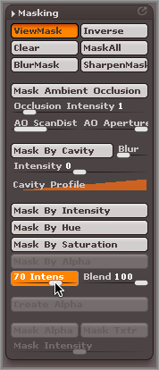
  • Toward the bottom of the Masking subpalette you’ll see a slider labeled Intens, as shown in the following image. This controls the intensity of the mask. The value of this slider is applied to the next mask painted on the surface; it does not affect any masks currently applied to the surface. If you set this to 50, the next mask you create will be at half the normal strength. This means that the surface will still be affected by changes you make with the sculpting brushes but only at half strength.
c03uf006.tif
  • There are many advanced masking features in the Masking subpalette, including Mask Ambient Occlusion and Mask By Cavity. These features will be covered in the sections on advanced sculpting techniques later in this book.

Mask Pen Stroke Types

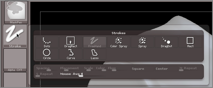
The MaskPen brush can use all of the stroke types that a regular sculpting brush uses and a few extra (Rectangle, Circle, Curve, and Lasso). To change the MaskPen brush’s stroke type, hold down the Ctrl key, and then open the stroke type fly-out library and click one of the stroke type icons (see Figure 3-25).

Figure 3-25: The MaskPen brush can use the same stroke types that are available for sculpting brushes plus a few special stroke types.

c03f025.tif
Tips on Using Stroke Types with the MaskPen Brush
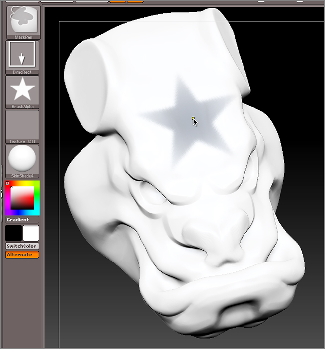
  • You can select an alpha texture from the alpha fly-out library to change the shape of the mask based on a 2D image. The following image shows how the Star alpha has been applied to a mask brush.
c03uf007.tif
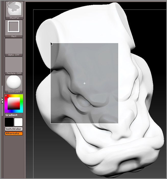
  • When you choose the Rect stroke type for the masking brush, you can then use the MaskPen brush to define a rectangular-shaped area to be masked. As you hold the brush down and drag, you can set the size of the masked area. The center of the mask is indicated by a white plus sign.
c03uf008.tif
  • Try not to confuse the Rect stroke type with the DragRect stroke type; they sound very similar but they behave very differently.
  • If you want to reposition the rectangular mask (Rect stroke type) while using the Rect stroke type, let go of the Ctrl key and hold down the spacebar. Once your mask is in position, release pressure from the tablet to apply the mask.
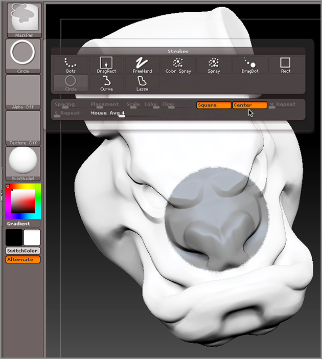
  • At the bottom of the stroke type fly-out library are two options: Square and Center. These buttons are shown in the following image. These options apply to the Rect and Circle stroke types. When the Square option is enabled, the masked area is always a perfect square. When the Center option is enabled, the center of the masked area is determined by wherever you initially click on the canvas. As you continue to drag, the mask is sized relative to the center. When Center is off, dragging out a corner of the rectangular area creates the mask.
c03uf009.tif
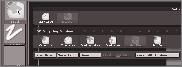
  • A number of masking brush presets already have some of these features enabled. These are the MaskCircle, MaskCurve, MaskCurvePen, MaskLasso, MaskPen, and MaskRect brush presets. These are shown in the following image. To choose one of these presets you can hold the Ctrl key and open the brush fly-out library on the left shelf. When you switch to a masking pen, it is mapped to the Ctrl key.
  • If you create a mask on a side of an object, the mask goes all the way through the surface and masks the opposite side as well.
  • The Circle stroke type behaves just like the Rect stroke type except that the selected area is an oval and not a rectangle. If you activate the Square option in the modifiers, the masked area will always be a perfect circle.
  • The Lasso stroke type lets you define a free-form area for the mask by drawing on the canvas while holding down the Ctrl key.
c03uf010.tif
  • The MaskCurvePen is a more advanced stroke type that will be discussed in Chapter 5, “ShadowBox and Clip Brushes.”

Masking is a big part of working with ZBrush. Before you move on to the next section, make sure you spend some time practicing. Open the DefaultSphere.ZPR project in Light Box and experiment with using masks and brushes on a simple surface.

Insert Brushes

The MeshInsert brush allows you to add a presculpted mesh to your model with a brush stroke. It’s a great way to add eyes, ears, teeth, and anything else you’d like to add to a surface. In this section, you’ll use the brush to add eyes to the dragon.

To use this brush successfully, you’ll need to understand the masking techniques of the previous section. You’ll also be introduced to the Transpose brush and learn a new way to generate digital clay.

Using the InsertSphere Brush to Add Eyes

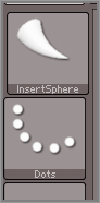
There are a wide variety of ways to add eyes to a creature or character in ZBrush. In this section, you’ll use the InsertSphere brush to add two simple spheres to the dragon’s head.

1. Open the most recent version of your dragon’s head model.
2. Make sure that the Dynamesh button in the Geometry subpalette of the Tool palette is still activated.
3. Make sure symmetry along the x-axis is still active. This is toggled on or off by pressing the X hotkey.
4. Open the brush fly-out library on the left shelf. Press the I key and then the P key to switch to the InsertSphere brush (upper-left image in Figure 3-26).
5. Rotate the view of the model so that you can see in the eye socket.
6. Drag on the surface deep in the eye socket; as you drag, you’ll see a sphere grow with the brush stroke. Don’t let go of the brush just yet! As you drag, you can adjust the size of the sphere by dragging left or right (the upper-right image in Figure 3-26).
7. When you are happy with the size, let go of the brush. The sphere is now placed, but notice that the rest of the head is instantly masked. This is convenient because it allows you to continue easily making adjustments to the sphere after drawing it out without affecting the rest of the model (lower-left image in Figure 3-26).

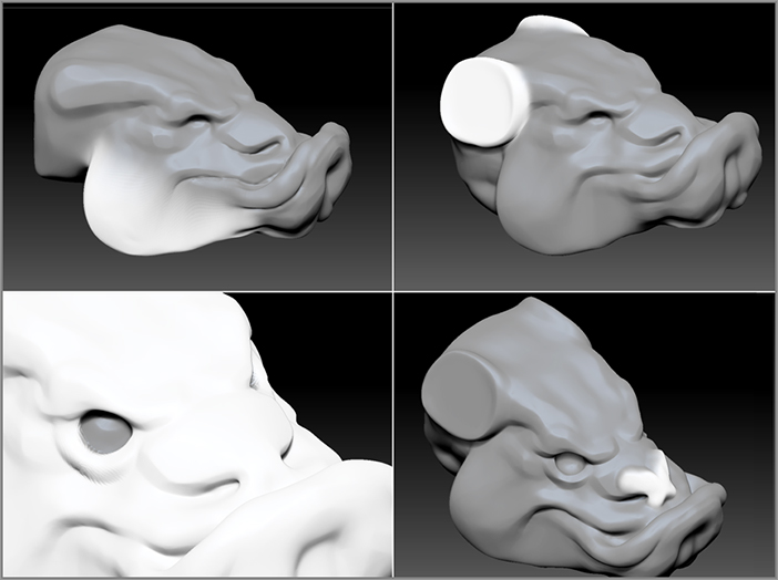
Figure 3-26: Select the InsertSphere brush from the brush library (upper left). Drag inside the eye socket to insert the sphere, and continue dragging to size (upper right). The model is automatically masked when you release the InsertSphere brush (lower left). After the sphere is inserted, it is fused with the rest of the surface using Dynamesh.

c03f026.tif
8. If you want to try that again, just press Ctrl+Z to undo, and try creating the eye again. I tried to scale mine so that there is just a slight gap between the eye socket and the sphere.
9. If you like the way the eye looks, Ctrl+drag on a blank part of the canvas once to clear the mask and then again to activate Dynamesh. Dynamesh fuses the eyeball sphere with the rest of the dragon’s head surface (see the lower-right image in Figure 3-26).
10. After placing the eye, I used the sculpting and masking brushes as well as Dynamesh to create an eyelid. Figure 3-27 shows the result with the BasicMaterial2 shader applied to the surface.

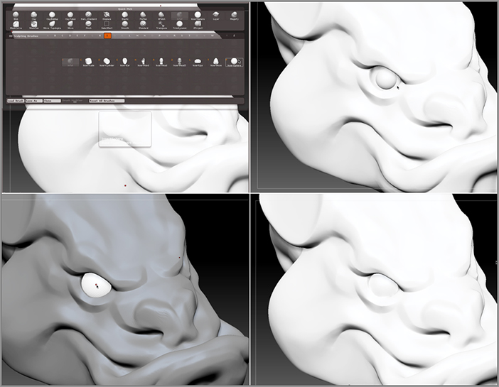
Figure 3-27: The sculpting and masking brushes are used to create the eyelid around the inserted eye.

c03f027.tif

This time I increased the Resolution slider under the Dynamesh button in the Geometry subpalette of the Tool palette to 256. This allowed me to retain more of the sculpted eyelid detail each time I activated Dynamesh.

The real power of the InsertSphere brush is that you can use it to insert your own custom mesh objects into a surface. You can customize the InsertSphere brush so that you can use it to add lips, even a whole robot arm to any model you create. This is true for the insertHead, insertCube, and many of the other insert brush types. But keep in mind that these brushes work best while your model is in Dynamesh mode.

In the next section you’ll see how you can use one of the parametric 3D primitives to create a nice sharp tooth and then see how you can use the insert brush to add the tooth to the model.

Creating Teeth Using Parametric 3D Objects

In this section you’ll create a tooth using a parametric 3D object. The 3D parametric objects are all contained in the ZBrush tool library. They are called parametric because you shape them using numerical controls and not the sculpting brushes. Once you have a shape you like, you can convert it into a regular 3D mesh that can then be sculpted with the brushes. It sounds a little confusing at first, but we’ll start simply with a basic tooth, which should make the idea clear.

1. Make sure the most recent version of your dragon’s head project is loaded into ZBrush.
2. Open the tool library in the Tool palette and select the Cone3D brush (see Figure 3-28).

Figure 3-28: Select the Cone3D object from the tool library.

c03f028.tif

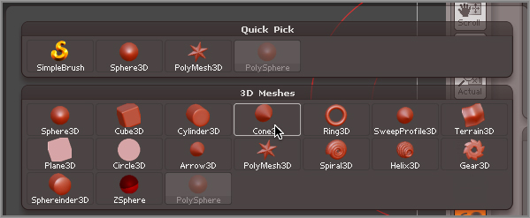
The dragon’s head will disappear, and you’ll see a cone on the canvas. Don’t worry; the dragon is just fine. By selecting a different tool from the Tool library, you’ve essentially moved the dragon off your virtual sculpting stand and replaced it with an instance of the cone. You can switch back at any time by opening the tool library and selecting the dragon’s head model. Most likely the model is still named PolySphere. We’ll talk more about organizing and renaming tools in Chapter 4, “Polymesh Editing.” For now let’s keep focused on the basics.

3. Try to touch the cone with the sculpting brush. You’ll get a warning telling you that you need to convert the primitive into a PolyMesh3D object (Figure 3-29). No need to do that just yet, but be aware that you get this warning whenever you try to sculpt a parametric object.

Figure 3-29: ZBrush displays a warning when you try to sculpt the cone.

c03f029.tif
4. Click the canvas to make the warning go away. At this point you don’t want to turn the model into a polymesh just yet. Before converting the cone into a polymesh, you will use the special sliders in the Initialize subpalette to shape the cone into a tooth.
5. Turn on the PolyF button on the right shelf so you can see the wireframe on the surface of the cone. This just makes it easier to see how the sliders in the Initialize subpalette affect the polygons of the mesh.
6. Select the Tool palette and expand the Initialize subpalette, which is located at the bottom of the Tool palette. Try adjusting the sliders; you’ll see the surface update as you make changes.

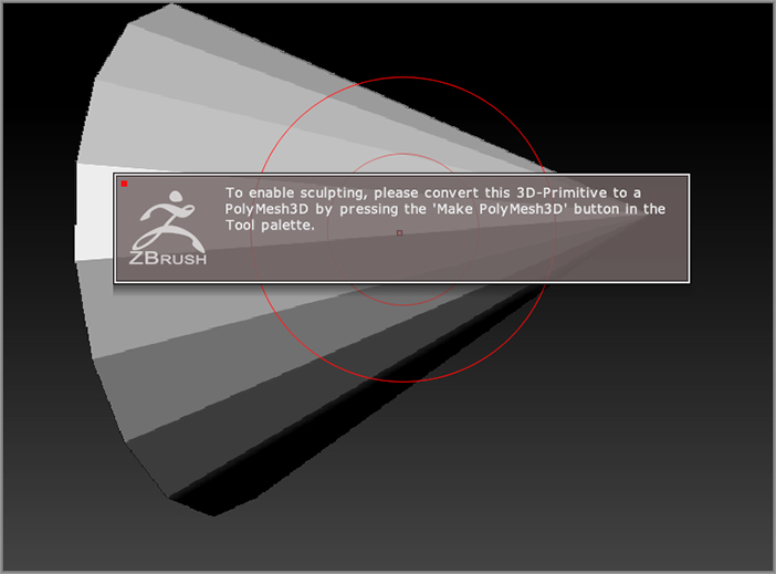
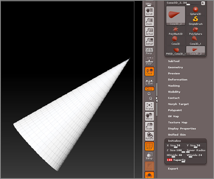
Using these sliders, you can decide how many divisions you want in the cone and whether the bottom is closed or has a hole through it.

7. Use the following settings for the Initialize subpalette in the cone:
X Size: 50
Y Size: 50
Z Size: 100
Inner Radius: 0
HDivide: 48
VDivide: 24
TaperTo: 100

The result should be a nice pointy cone, as shown in Figure 3-30.

Figure 3-30: The cone is shaped using the sliders in the Initialize subpalette of the Tool palette.

c03f030.tif

Now that the cone has been shaped parametrically, you can convert it into a sculptable mesh.

8. At the top of the Tool palette click the Make PolyMesh3D button (see Figure 3-31). You won’t see much happen to the cone. If the PolyF button is on, it will change color (this color change will be explained in Chapter 4).

Figure 3-31: The Cone3D object is converted into a sculptable polymesh object by clicking the Make PolyMesh3Dbutton in the Tool palette.

c03f031.eps
9. Turn off the PolyF button. Try touching the surface with a sculpting brush. Now the warning does not appear, and you can see that the brush is affecting the surface (see Figure 3-32).
10. Press Ctrl+Z to undo any of the changes in the cone.

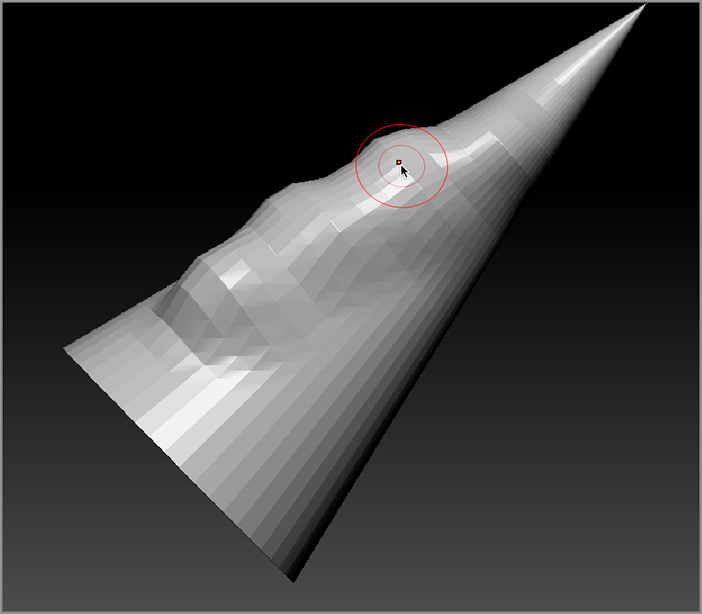
Figure 3-32: Once converted to a polymesh object, the cone can be sculpted with the sculpting brushes.

c03f032.tif

It’s important to understand that when you click the Make PolyMesh3D button, ZBrush actually creates a mesh copy of the parametric tool you’re working on. In fact, if you open up the sculpting library you’ll see two cones, one labeled Cone3D and the other labeled PM3D_Cone3D_1 (see Figure 3-33). Cone3D is the original cone and PM3D_Cone3D_1 is the mesh copy. This is actually very convenient because you can switch back to the original Cone3D object, make more changes with the sliders in the Initialize subpalette, and then make another copy with the Make PolyMesh3D button. Using this method you can quickly generate as many variations on the original cone as you like.

Figure 3-33: A polymesh copy of the parametric Cone3D tool is placed in the tool library when you click the Convert to PolyMesh3D button.

c03f033.tif
3D Parametric Objects
The great benefit of using 3D parametric objects is that they allow you to quickly create shapes that would be very difficult to do using the sculpting objects alone. I use them all the time for creating mechanical parts, horns, teeth, and even sea shells. The sliders in the Initialize palette determine their shape. You can find out more information on what a slider does by holding the Ctrl key while the cursor is over the slider. Here’s a description of each object and some tips on how you can use them:
Sphere3D This basic sphere has a pole at either end. Use the X Size, Y Size, and Z Size sliders in the Initialize subpalette of the Tool palette to shape the sphere into oblong spheroids. Use the Coverage slider to make the sphere a dome. The HDivide and VDivide sliders determine the horizontal and vertical divisions. In the following image you can see how a slice is removed from the Sphere3D by adjusting the Coverage slider.
c03uf011.tif
Cube3D At first this looks like a common cube, but it actually has a few surprises that you can discover when you play with the sliders in the Initialize subpalette. Like the Sphere3D, you can change the dimensions of the cube using the X Size, Y Size, and Z Size sliders. The Sides Count changes the number of sides around the z-axis, so you can change the cube into a hexagonal column or even a cylinder. The Twist slider twists the sides around the z-axis. This tool is great for fancy columns, drill bits, or modern architecture. In the image on the right of the previous graphic, the cube has been twisted around the z-axis.
Cylinder3D This object can be easily turned into a hollow pipe by adjusting the Inner Radius slider. You can also use the TaperTo slider to make one end narrower than the other.
Cone3D This object is essentially the same as the Cylinder but the TaperTo slider in the Initialize palette is preset to a value of 100, making it into a cone.
Ring3D This is an indispensible tool for making donuts and horns, or even demonic donuts that have horns. Use the SRadius slider to determine the thickness of the ring; use Coverage to make the ring open or closed. Scale adds a taper to one end of the ring. The Twist slider rotates the polygons of the surface around the axis, adding a twist along the surface. In the following graphic, Ring3D is shown on the left.
c03uf012.tif
SweepProfile3D This versatile tool uses a curve editor to determine its shape. This type of editor is a curve on a two-dimensional graph. You add points to the curve and drag them to shape the curve, which, in turn, shapes the object. The best way to understand this is to play with the curve. The Sweep Profile uses the S Profile curve to determine the shape and the T Profile curve to determine the thickness. The T Profile curve works only when the Thickness slider is above or below 0. This object is a great way to start lamps, goblets, and other lathed-type shapes. In the previous graphic, you can see how the curve is used to shape the sweep profile in the image on the right.
Only one Edit Curve interface can be open at a time. To expand the Edit Curve, click the collapsed graph; to close it, either open another curve editor or click the Close bar below the graph.
Terrain3D Like the Sweep Profile, this surface is shaped with two curve editors. The V Profile curve shapes the vertical profile, and the H Profile shapes the horizontal profile. This tool works well as a starting place for flowing fabric or rolling hills.
Plane3D This is pretty much just a plane. You can determine the size using the H Radius and V Radius sliders.
Circle3D This object is a flat circle. The outside radius is set using the ORadius1 and ORadius2 sliders; the inside radius is set using the IRadius1 and IRadius2 sliders. Using these sliders you can create some interesting abstract designs.
Arrow3D This object is like the cylinder with a cone on top. The TipR and TipH sliders set the radius and height of the tip. The InnerR sets the inner radius and the InnerI sets the inner inset. The BaseR and BaseL sliders set the radius and inset of the base. The Double button mirrors the pointed end to the opposite side of the arrow. This object is a good starting place for spikes, simple trees, and weapons.
Spiral3D This object has slider controls very similar to the Ring3D object, but it has additional controls that allow you to offset the helical shape of the surface, which is perfect for creating horns for rams, curling snakes, or snail shells.
Helix3D This is very similar to the Spiral3D except that instead of using numerical sliders it uses edit curves to determine the shape. This means that you have more control over the look of the object, so there is more variety in the types of surfaces you can make.
Gear3D This is the perfect tool for creating mechanical parts. The Initialize palette for the Gear3D object has a mixture of sliders and edit curves. I often find myself playing with these settings for hours on end because of the amazing number of options available. The following image shows a model created using the Gear3D tool after about 5 minutes of noodling with the various curve editors in the Initialize subpalette.
c03uf013.tif
When you use the curve editor to change the shape of a particular attribute, you can click on the curve to add a point, drag the point off the curve to remove it, adjust the circle around the point on the curve to edit its influence, and create a sharp angle in the curve by dragging a point off the curve editor and then back on again. As with many aspects of ZBrush, you should take some time to practice using the curve editor.
Sphereinder3D As the name suggests, this tool is a combination of the Sphere and the Cylinder. It’s great for making capsules or cylinders with rounded edges.
The 3D parametric objects are a great source for creative exploration. As I noted before, the general workflow is to select one of the objects that most closely resembles what you want to create, then shape it using the sliders and curves in the Initialize subpalette, and when you’re happy, click the Make PolyMesh 3D button at the top of the Tool palette. This makes a copy of the object, which you can now shape with the sculpting brushes.
It can be confusing when the tool library starts to fill up with copies of your objects. Keep in mind that only the parametric objects have an Initialize subpalette, and the polymesh copies start with the prefix PM3D_.

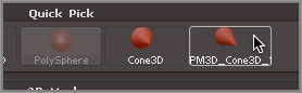
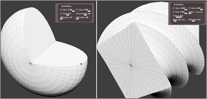
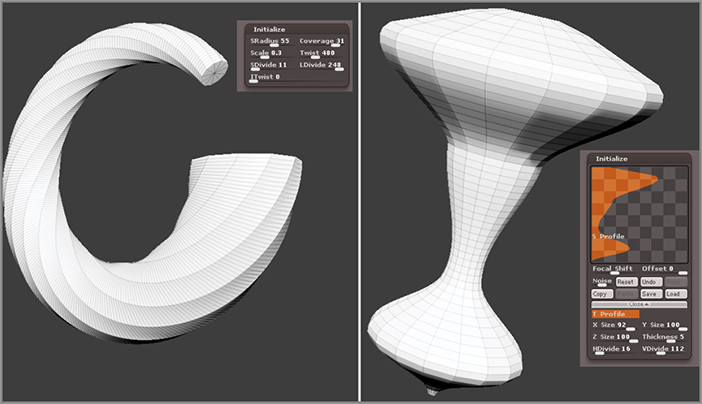
Figure 3-34: The deformers are a set of sliders found in the Deformation subpalette of the Tool palette.

c03f034.tif

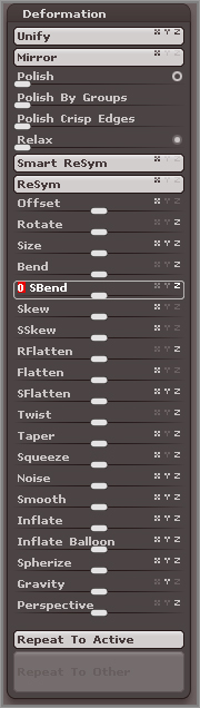
Bending the Tooth Using Deformations

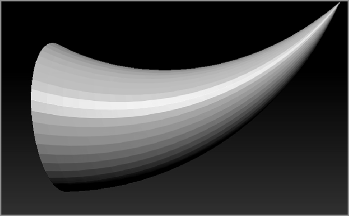
Now let’s put a slight bend in the tooth to make it more like a dragon’s tooth. To do this, we’ll use the Smooth Bend deformer in the Deformations subpalette of the Tool palette. The Deformation subpalette contains a large number of sliders, each of which can be used to deform your surface, allowing you to twist, mold, bend, and manipulate the overall shape of your object with numerical precision (see Figure 3-34).

1. Open the Deformation subpalette of the Tool palette. Find the SBend slider. You’ll see very tiny letters (X, Y, and Z) to the right of the SBend slider. These letters establish the axial direction for the deformation. You can turn them on or off by clicking them. Click the letter so that only Y is highlighted and X and Z are grayed out.
2. Nudge the slider to the right; as you do this, you’ll see the cone bend. You need to bend it only slightly. A value of about 15 should work fine. If you go too far, just press undo (Ctrl+Z) and try again (see Figure 3-35). The bent tooth is shown in Figure 3-36.

Figure 3-35: Set the SBend axis to Y, and set the deformer value to 15.

c03f035.tif

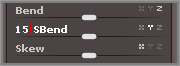
Figure 3-36: The dragon’s tooth is created by applying the SBend deformer to the polymesh cone.

c03f036.tif
Deformation Slider Values
Whenever you want to put an exact value into a slider such as a deformer, select the slider name; after a second you’ll see the number 0 highlighted, and you can then type in the precise value of the slider. This can be a little easier than trying to move the slider to get an exact value.
The actions of the deformations are cumulative. In other words, if you set SBend to 20, then the deformer bends the surface by a factor of 20. Type 20 again, and it bends it again by another factor of 20. To get the object to deform in the opposite direction, you can move the slider to the left or type in a negative number. You can always undo the action of a deformer. Sometimes it takes a few tries to get exactly what you want. To find out more about what each deformer does, hold the cursor over the slider and press the Ctrl key.
3. Once you have a nice-looking tooth, it’s a good idea to save the project using the Save As button in the File menu. When you save a project, all of your tools are saved as well, including the dragon head and the tooth (both the original parametric tooth and the polymesh version).

Using the Insert Brush to Add the Tooth to the Dragon

Now that you have a tooth modeled, it’s time to add it to the dragon. Just like with the eye, you’ll use an insert brush to accomplish this. The first step is to edit one of the existing brushes so that it will allow you to add the tooth created in the previous sections by simply dragging on the model.

1. Open your most recent version of the dragon’s head model by clicking the Open button in the File palette.
2. Open the sculpting brush library and choose the InsertSphere brush (or any of the other insert brushes).
3. Open the Brush palette at the top of the interface, and expand the Modifiers subpalette. I find it helpful to place the Brush palette in the tray on the right of the screen (as shown in Figure 3-37). You’ll see a little window with a red sphere in it. Click this window to open the tool library. Select the PM3D_Cone_1 tool from the library. This is your dragon’s tooth created in the previous sections (it’s possible that your tool may have a slightly different name depending on how many cone tools you created in the previous exercise; just make sure it is the bent cone and you should be fine).

Figure 3-37: Use the Modifiers subpalette of the Brush palette to select the tooth from the tool library.

c03f037.eps
4. When you select the tooth model, notice that the icon for the brush in the palette also changes (see Figure 3-38). The brush is still named InsertSphere.

Figure 3-38: The icon for the InsertSphere brush changes automatically.

c03f038.tif
5. Now to insert the tooth, rotate the view of the dragon so you are looking at it from the top. See if you can find a good spot to place a tooth. Be sure symmetry is enabled (hotkey = X) and drag on the surface of the model. Symmetry will cause ZBrush to create a copy of the tooth on the other side of the dragon as well.
Saving Your Tooth Brush
You have just created your first custom brush! This brush can be used to insert the tooth as long as this session of ZBrush is open. But what if you want to use this brush again for future toothy monsters? You can simply click the Save button in the Brush palette to save the brush and reopen it later on. To do this, follow these steps:
1. Open the Brush palette and click the Save As button at the top of the palette.
2. Use the Save dialog box to save the brush as insertTooth.zbp. Save this file in the Pixologic/ZBrush 4 R3/ZBrushes/Insert folder. Then you can find it in Light Box in the Brushes/Insert folder. (Mac users note that this folder is found in ApplicationsBrush 4R3BrushesInsert.)

The tooth appears in the mouth, and as you drag it, the tooth continues to grow in size. If the dragon’s head disappears while you are dragging, don’t panic; once you let go, the head reappears.

6. Let go of the brush once you have a medium-size tooth (see Figure 3-39). You’ll notice that the head become instantly masked when you let go (if this does not happen, double-check that the Auto Mask Mesh Insert button is enabled in the Auto Masking subpalette of the Brush palette).
7. Save your project by clicking the Save button in the File palette.

Figure 3-39: The tooth is placed in the dragon’s mouth from above.

c03f039.tif

It’s highly unlikely that the placement of the tooth was exactly what you want. You can undo and try again, but you might find yourself going crazy trying to get it perfect using the InsertTooth brush alone. This is why the dragon’s head is instantly masked when you insert a mesh. It allows you to adjust the inserted mesh after you draw it into the object without affecting the original surface.

After you insert the mesh, you’ll need to perform a few more steps to get it positioned perfectly. The first time you do this it may feel a bit overwhelming, but it actually becomes very intuitive and fast with a little practice. In the next section you’ll learn how you can use the versatile Transpose brush to move, scale, and rotate the tooth.

Using the Transpose Brush to Position the Tooth

The Transpose brush is a special type of brush that lets you move, scale, and rotate your meshes. Generally it’s used in conjunction with masking as a way to pose figures or move individual parts of an object. In this section, you’ll learn the basics of using it as a way to position the tooth you’ve added to your dragon’s head.

The Transpose brush is activated when you click the Move, Scale, or Rotate button on the top shelf while a mesh is in Edit mode, or you can select the Transpose brush from the sculpting brush library. When you select this brush, the brush cursor changes into a line with three pairs of concentric circles (see Figure 3-40). One pair of circles is at the center, and the other two are at either end of the line. The line that connects the three pairs of circles is known as the action line, and it determines the central axis of the control.

Figure 3-40: The Transpose control looks like a line connecting three pairs of concentric circles.

c03f040.tif

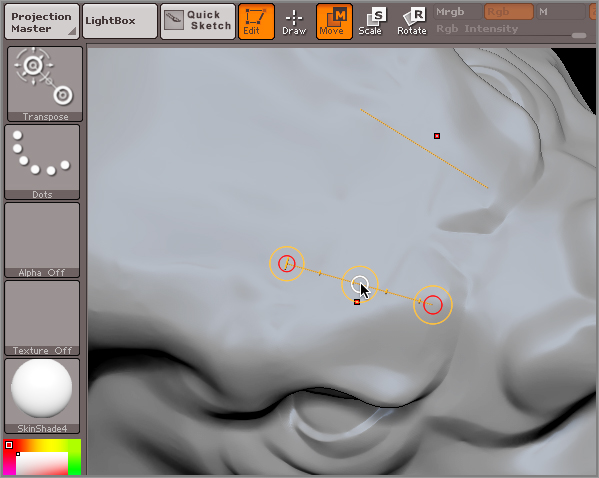
The three pairs of circles along the action line are the handles. The outside circle of each pair is used to position the control, and the inside circle of each pair is used to pose the mesh. It takes a little practice, but after some experimentation, you’ll find that using the control becomes easy. I like to think of the Transpose brush as a virtual wrench. Any part of the surface that is not masked can be pulled, scaled, or twisted as you move around the handles of the brush.

The following demonstrates how to use the Transpose control to position the tooth you inserted into the mouth in the previous section:

1. Continue with the model from the previous section or click the Open button in the File palette to open the most recent version of your dragon’s head. Make sure that the mask is still applied to the head and that the teeth remain unmasked.
2. Make sure the Persp button on the right shelf is off. This is not always necessary, but I find that it’s easier to move parts of the object precisely when Perspective mode is off.
3. Rotate the view of the dragon’s head so that you are looking at it from the side. Remember that as you rotate the view, you can hold the Shift key to snap it into place for a perfect side view (yes, it takes a little practice as well!).
4. Open the Sculpting Brush palette and press the T key for transpose and then R to select the brush. Alternatively, you can click on the Move button on the top shelf.

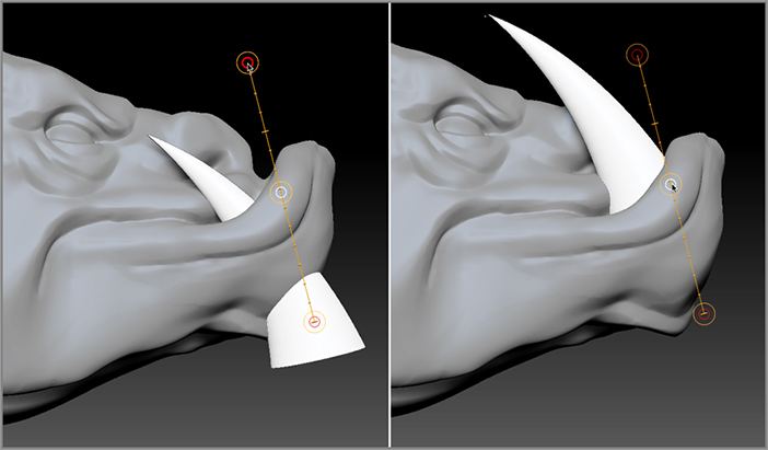
In the case of my dragon, the teeth are very large and stick out of the bottom of its jaw. I’m going to start by moving the teeth up, and then I will scale them down and finally rotate them. Since symmetry is activated, anything I do to one tooth will be mirrored to the tooth on the opposite side.

5. Click the bottom part of the tooth in the side view, and drag upward to a blank area on the canvas. As you do this, the Transpose brush draws out the line with the circular handles. No need to be overly precise when doing this, just a general position is fine (Figure 3-41, left image).
6. Hold the cursor over the center circle; you’ll see a second white circle appear at the center or the handle; drag upward on the center circle to move the tooth up. Continue to drag on this until you have the tooth in a rough position, situated in the mouth but poking out from behind the lower lip (Figure 3-41, right image).
7. Now to scale the tooth down, click the Scale button on the top shelf or press the E hotkey. The Transpose brush looks the same, but you’ve just switched to Scale mode.
8. Drag again from the bottom of the tooth toward the top to create a new handle. Select the center of the circular handle at the top of the tool, and drag downward toward the opposite end of the handle. This scales the tooth down. Repeat this dragging action a few times until the tooth is a more reasonable, yet still fearsome size (Figure 3-42, left).

Figure 3-41: Draw the Transpose line from the bottom of the tooth to the space above the head (left image). Drag on the center circle to move the tooth into position (right image).

c03f041.tif

Keep the idea of a virtual wrench in mind; it’s a good way to visualize how Transpose works. Basically, each handle on the Transpose brush works in a different way.

The Fundamental Rules of Transpose
  • The outer circle of each handle lets you position Transpose in 3D space. Drag on the outer circles at the end of the handle to position the ends.
  • The inner circle of each handle deforms the unmasked parts of the mesh based on the current mode (Move, Scale, or Rotate) of Transpose.
  • The circle on the opposite side of the Transpose handle sets the pivot point from the deformation.
  • The hotkeys for each mode of the brush are Move = W, Scale = E, and Rotate = R.
  • More advanced Transpose techniques are discussed in Chapter 4.
9. To rotate the tooth, click the Rotate button on the top shelf or press the R hotkey. Drag on the tooth again from the bottom toward the top, but this time drag into empty space above the tooth.
10. Just as in step 8, select the center of the circle in the top handle, and drag it left or right to rotate the tooth. Notice that the pivot point of rotation is the circle at the opposite end of the Transpose handle. You can change the pivot point by simply dragging on the outer circle of the handle at the opposite end (Figure 3-42, center image).
11. Rotate the view of the head so that you can see it from the top. Try dragging out a new handle and rotate the tooth again. You can see that because symmetry is active, the tooth on the opposite side is affected as well (Figure 3-42, right image).

Figure 3-42: The tooth is scaled and rotated using Transpose. Because symmetry is activated, changes on one tooth are mirrored to the tooth on the opposite side.

c03f042.tif
12. Spend some time practicing moving, scaling, and rotating the tooth until you like the way it is positioned. Be careful not to clear the mask on the surface. As long as the head is masked, you should be able to easily manipulate the tooth without affecting the work you’ve done on the head.
Mastering Transpose
Many beginning students have a bad, if not allergic, reaction to the Transpose brush. It’s not like anything you’ll find in another 3D program, and I’ve had a number of students give up in frustration when they first encounter these techniques. The tool seems to defy all logic.
In reality it’s an amazing feature, but it does take practice. If you spend 30 minutes transposing an object using this tool, you’ll be on your way to mastering it. Patience is the key.
Before Transpose was introduced in version 3 of ZBrush, digital sculptors would often export their model, rig it in another program such as Maya, pose the rigged version, and then export and reimport it into ZBrush. That can take a few hours even for an experienced modeler.
With ZBrush you’ll find that you can skip all the exporting and rigging and posing and focus on posing each part of the model at any stage of its development.
One thing that can trip you up is if two symmetrical surfaces, such as the dragon’s teeth, overlap along the center line. If symmetry is enabled, you can find that the overlapping parts become all stretched and stuck together. The best way to avoid this is careful placement of the surfaces when you use the insert brush. Make sure that the surfaces are not too close together as you place them. This is why I suggested placing the teeth from a top view of the dragon.
13. Once you have your tooth scaled, rotated, and positioned, click the Save button in the File palette to save your work.

In the next section, you’ll learn a great trick for quickly duplicating the teeth. And you’ll finish the head of the dragon with some nice curling horns.

Duplicating the Teeth Using Transpose

In this section you’ll learn a cool trick for duplicating objects using the Transpose brush. Using this technique you’ll add a row of teeth to the dragon’s head you’ve been developing throughout this chapter.

1. Click the Open button in the File palette to open the most recent version of your dragon’s head. Make sure that the mask is still applied to the head and that the teeth remain unmasked.
2. Press the W hotkey to switch to the Move mode of Transpose.
3. Using the Transpose brush, drag an action line across the tooth. Again, you don’t need to be overly careful, as long as you can clearly see the center circle of the tool.
4. Drag the center circle of the Transpose handle while holding the Ctrl key. This instantly duplicates the unmasked surface. The original tooth is now masked along with the rest of the head.
5. Use the Transpose brush to position the new tooth next to the original. Since symmetry is still enabled, a mirrored copy of the tooth has been duplicated on the other side (Figure 3-43, left image).
6. Press the E hotkey to switch to Scale mode, and scale down the duplicate tooth.
7. Press the R hotkey to switch to Rotate mode, and rotate the tooth into a better position. If the teeth are all perfectly aligned, the dragon will not look quite as fierce (Figure 3-43, right image).

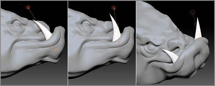
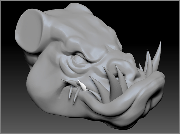
Figure 3-43: The tooth is duplicated and moved toward the center using the Transpose brush (left image). The duplicate tooth and its mirror copy are scaled and rotated using the Transpose brush (right image).

c03f043.tif
8. Repeat these steps to add a number of teeth that poke out between the lips. Make the teeth different sizes and rotate them in different directions. You can see how I have used this technique in Figure 3-44.

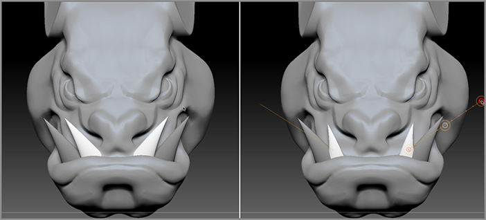
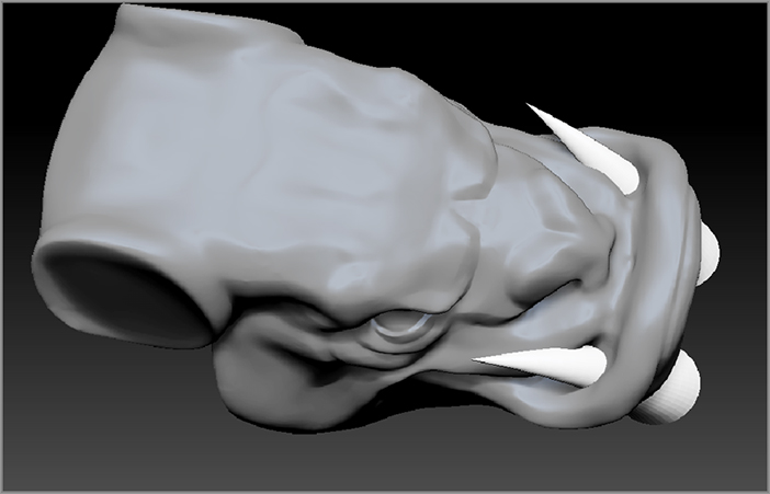
Figure 3-44: Multiple teeth are created by duplication with the Transpose brush. The teeth are scaled and rotated to create a gruesome array.

c03f044.tif
9. Once you feel like you have enough teeth, click the Save button in the File palette to save the project.

Adding Horns to the Dragon Head

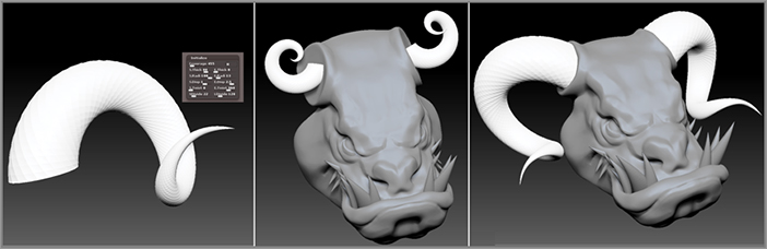
You’ll notice that in my version of the dragon I have two round, flat areas on either side of the head. I created these with the intention of adding horns to the surface. To add horns, I used the same techniques as I demonstrated with the teeth. Instead of using the Cone parametric tool to make the horns, I used the Spiral3D tool. I created my own InsertHorn brush from a polymesh version of the Helix3D tool and then inserted into the mesh. I then used Transpose to align the horns on the head correctly. Figure 3-45 shows stages in the process. I recommend trying these techniques on your own model as a way to review the techniques described in this chapter. ZBrush gets much easier with practice. I highly recommend going through these steps.

Figure 3-45: Horns of the dragon are created using the Spiral3D tool and then inserted using a customized insert brush. Using the Transpose brush they are moved, scaled, and rotated to match the head.

c03f045.tif

It may take a while to get the horns aligned. Remember that you can invert the mask (Ctrl+I) and use the Move brush to make the flesh of the dragon head meet the end of the horns. Just make sure that you don’t clear the mask entirely!

Save the file when you are happy with the placement of the horns. Don’t worry about detail just yet. In the next chapter you’ll take this model even further as you learn about polygroups, subtools, and ZSpheres.

To see a version of the head that I created up to this point, open the dragonHead_v01.ZPR project from the Chapter 3 folder on the DVD that comes with this book. I also included my insertTooth.zbp brush and my insertHorn.zbp brush. You can load these brushes using the Load button in the Brush palette.

ZBrush Practice
There is a common misconception that art generated on a computer is the product of simply pressing a few buttons. Many feel that if they can’t create great-looking images instantly on their first try, then the problem lies with the software. This is simply not true.
Computer art is a medium, just like pencil, clay, and paint. You will only get better with practice. Some people take to ZBrush like a fish to water, just as some people seem to be able to play the piano perfectly from the first time they touch the keyboard. But trust me, I’ve had students who excel instantly and students who struggle (and I have struggled much over the years as well!). In the long run, it’s only the students who practice who do well. The work of my students who struggled a year ago but kept practicing is indistinguishable from the work of students who seemed to be great from the first time they tried ZBrush. In fact, sometimes the work of those who struggle and persevere is even better! If this chapter has been a challenge, then just try it again. Keep it up until it clicks, and you’ll be amazed at what you can create! It’s a lot like skiing. The first day of skiing you get a lot of snow in your face, but at some point, after falling down enough times, everything suddenly makes sense and you’re flying. Keep going until it works; trust me, it is worth it!

Summary

In this chapter you’ve taken your first steps into the world of digital sculpting with ZBrush. You’ve learned how to take a simple polymesh sphere and shape it into the form of a dragon’s head using the sculpting brushes. You’ve learned how to use Dynamesh to create a sculpting-friendly topology and how to add parts using parametric 3D objects and Transpose.

In Chapter 4, “Polymesh Editing,” you’ll learn how to organize the mesh using polygroups, how to create a simple multi-object hierarchy using subtools, and how to work with ZSpheres to create an armature for your model.

..................Content has been hidden....................

You can't read the all page of ebook, please click here login for view all page.
Reset
18.218.15.205