Chapter 5

ShadowBox and Clip Brushes

The digital sculpting tools you’ve encountered so far in this book lend themselves very well to the creation of organic surfaces. Subjects such as creatures, characters, clothing, and natural environments are easily achieved using sculpting brushes, ZSpheres, and ZSketching. ZBrush has long held the reputation of being the best way to create these kinds of organic objects.

ZBrush also has several tools that are designed to expand the power of digital sculpting to hard-surface objects as well. Things like vehicles, buildings, robots, and armor can now be created just as easily as organic surfaces.

This chapter introduces some tools that you can use to sculpt hard-surface objects including the ShadowBox tool, clip brushes, and curve brushes.

This chapter includes the following topics:

  • Creating meshes with ShadowBox
  • Using radial symmetry in ShadowBox
  • Using custom alphas in ShadowBox
  • Refining surfaces using clip brushes and ClayPolish
  • Using the InsertCube brush to cut into a surface

ShadowBox

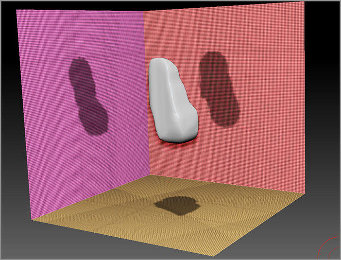
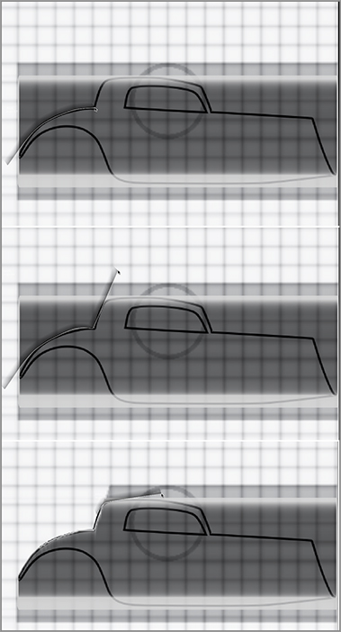
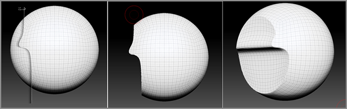
ShadowBox offers a completely different way to create meshes than anything you’ve seen in other 3D modeling packages. The technology is included as a special tool in ZBrush, and you’ll find that once you get the hang of the basic concept, it’s easy to use and a lot of fun. In a nutshell, here’s how ShadowBox works: A mesh is generated at the center of the ShadowBox tool based on the intersection of profiles that you draw on the three sides of the box (see Figure 5-1). You create the silhouettes on the sides of the box using the masking brushes, and as you edit the silhouettes the mesh at the center of the box instantly updates. Once you have the basic shape you want, you can turn ShadowBox off and you’re left with a mesh that you can then refine using the sculpting brushes, Dynamesh, and other techniques. It’s a very fast way to get an idea into three dimensions. Just as with the other ZBrush tools, the approach is artistic and intuitive, and there are only a few technical details that you need to worry about.

Figure 5-1: ShadowBox creates a mesh using silhouettes drawn on each side of a three-sided box.

c05f001.tif

Creating a ShadowBox

The easiest way to get started with ShadowBox is to open the ShadowBox128.ZPR project found in Light Box.

1. Start a new ZBrush session.
2. Open Light Box to the Projects section and open the DemoProjects folder.
3. Scroll to the left and find the ShadowBox128.ZPR icon (see Figure 5-2); double-click the icon to open the project. After a few seconds the project will open.

Figure 5-2: Open the ShadowBox128.ZPR project in the Projects/Demo Projects folder in Light Box.

c05f002.tif

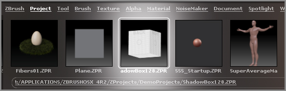
The project consists of a cube that has three sides visible. This is a ShadowBox tool. You’ll create your surfaces inside the box by drawing masks on the side. It’s kind of weird but also very cool.

4. Rotate the view of the ShadowBox so that you can see the three sides, hold the Ctrl key to activate the MaskPen brush, and drag on one of the sides to paint a mask.

When you let go to complete the stroke, you’ll see a flat blob appear at the center of the ShadowBox tool. The profile of the blob matches the shape of the mask painted on the side of the ShadowBox.

5. Turn on the Transp button on the right shelf. Make sure the Ghost button on the right shelf is activated, and rotate the view. Now you can see the mask on the side of the ShadowBox through the blob at the center (see Figure 5-3, left image).

Figure 5-3: Paint a mask on each side of the ShadowBox to create a mesh at the center.

c05f003.tif
6. Paint another mask on the other side of the ShadowBox (see Figure 5-3, middle image).

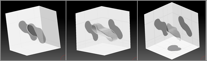
Figure 5-4: Click the ShadowBox button in the Geometry subpalette of the Tool palette.

c05f004.tif

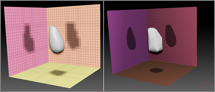
When you let go, the blob at the center updates. If you rotate the view, you’ll see that from the sides, the profile of the blob matches each of the masks drawn on the sides of the ShadowBox. As you view the blob from a perspective view, you’ll see that the shape of the blob is determined by the combination of the two masks.

7. Paint a third mask on the bottom of the ShadowBox. You can see that the blob is now generated based on the combination of the three masks (see Figure 5-3, right image).
8. In the SubTool subpalette, click the ShadowBox button in the Geometry subpalette of the Tool palette (see Figure 5-4). The box disappears, and you are left with the blob that was generated from the masks. At this point you have a mesh that you can subdivide and sculpt just like any other lump of digital clay (see Figure 5-5).

Figure 5-5: The resulting mesh created from painting masks in ShadowBox

c05f005.tif

This is the basic workflow for creating a mesh using ShadowBox. However, you can get much greater control by taking advantage of the various options the mask brush has to offer. In the next sections, you’ll learn how you can adjust the resolution of the mesh and how to use reference images within the ShadowBox tool.

The ShadowBox Tool

ShadowBox is a 3D tool similar to other 3D tools in that many of the options for controlling ShadowBox are found in the Tool palette, specifically in the Geometry subpalette of the Tool palette. You can also append the ShadowBox tool as a subtool to any existing 3D tool. This is a great way to add details to an object.

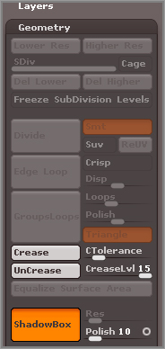
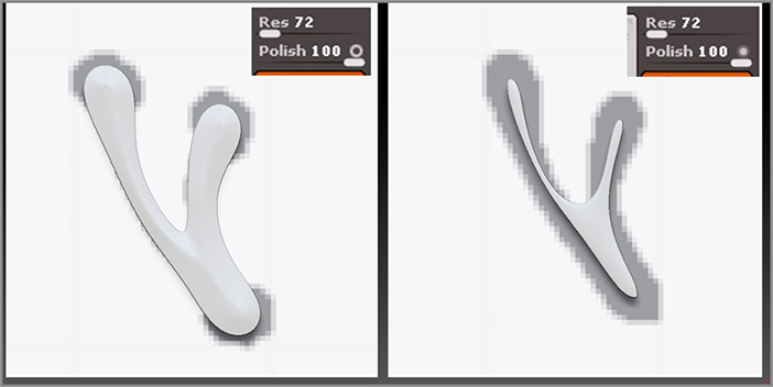
ShadowBox uses the unified skin method for generating the mesh created by the mask profiles. This means that the mesh is made up of quadrilateral polygons; this type of mesh is similar to the kind of mesh you create when you activate Dynamesh. So how do you set the number of polygons for the ShadowBox mesh? You do this using the Res slider in the SubTool subpalette of the Tool palette. The smoothness of the mesh can be adjusted using the Polish slider. However, you must set these sliders before you create the ShadowBox tool. Here are some tips on how to adjust the resolution of ShadowBox:

1. Continue with the tool created in the previous section. Click the ShadowBox button in the Geometry subpalette of the Tool palette.

The ShadowBox appears again, and the masks are regenerated on each side of the ShadowBox based on the profiles of the selected subtool.

2. On the right shelf, click the PolyF button to activate the wireframe display. Turn off the Transp button as well.

The wireframe appears on each of the sides of the ShadowBox (see Figure 5-6). This gives you an indication of the density of the mesh created by ShadowBox. Also, notice that the ShadowBox tool has been organized into color-coded polygroups so that each side is in its own polygroup.

Figure 5-6: The wireframe display appears as a grid on each of the sides of the ShadowBox tool.

c05f006.tif

While the ShadowBox button is on, the Res slider is grayed out. In order to change the resolution of ShadowBox you need to leave ShadowBox by turning this button off, adjust the resolution, and turn ShadowBox back on.

3. Turn the ShadowBox button off, and you’re left with a blobby little mesh but the Res slider is now available.

Take a look at the controls above the ShadowBox button in the Geometry subpalette of the Tool palette. The Res slider determines the resolution of the mesh, or in other words, the number of polygons that make up the surface of the mesh. The Polish slider determines how smooth the mesh is.

4. Set the Res slider to 244, and click the ShadowBox button once to turn ShadowBox back on.

Notice that the squares that make up the wireframe display on the sides of the ShadowBox are larger and that the mesh at the center of the ShadowBox is at a lower resolution (see Figure 5-7, left image). At a setting of 24, each side of ShadowBox is made up of a grid that is 24 × 24 polygons.

Figure 5-7: At a lower Res setting, the grid on the sides of the ShadowBox is larger and the resolution of the mesh is lower (left image). Higher-resolution settings for ShadowBox produce smoother masks and a denser mesh (right image).

c05f007.tif
5. Turn the ShadowBox button off, set the Res slider to 400, and then turn ShadowBox on again.

This time the grid on each side of the ShadowBox is very dense, and the mesh at the center is at a much higher resolution. Notice that the edges of the masks on each side of the ShadowBox are smoother as well. The quality of the mask is directly related to the resolution of ShadowBox (see Figure 5-7, right image).

There are different approaches to how you use ShadowBox, and depending on how you want to use the mesh generated by ShadowBox, you may want to choose a medium or low resolution or a high resolution.

The purpose of ShadowBox is to allow you to quickly determine the shape of a surface, which you can then subdivide and sculpt with the sculpting brushes. If you plan to subdivide the mesh after you leave ShadowBox, then you may want to choose a low resolution so that you can take advantage of having a range of SDiv levels to work with. But if you plan to convert the mesh into a Dynamesh surface, then you can choose a higher ShadowBox resolution since Dynamesh is going to automatically retopologize the surface anyway. The workflow is very flexible, and how you choose to incorporate ShadowBox into your modeling process is up to you.

6. Turn ShadowBox off again, set the Res slider to 256, and set the Polish slider to 0. This time notice that the surface of the mesh is very “blocky” (see Figure 5-8).

Figure 5-8: Setting Polish to 0 creates a blocky-looking mesh.

c05f008.tif

The Polish slider determines the smoothness of the mesh surface. Without smoothing, the surface will appear very blocky and rough. In some cases, you can use this aspect of ShadowBox as a creative advantage. Using a low or 0 Polish setting with a rectangular mask is a great way to create hard-edged surfaces. Later in this chapter you’ll see how to use rectangular masks in ShadowBox.

7. Experiment with different Polish settings and see how they affect the appearance of the mesh.

You can save the ShadowBox tool for future use, and the settings you have established will be included whenever you load the tool into ZBrush.

8. Turn ShadowBox off, and set the Res slider to 256 and the Polish slider to 10. This will establish the settings for the tool. Then turn ShadowBox back on.
9. Hold the Ctrl key and drag on the canvas to clear any masks that may be drawn on the sides of the ShadowBox. Clearing the masks will also clear any meshes that may be at the center of the ShadowBox.
10. Now click the Save As button in the Tool palette and save the tool as ShadowBox256.ztl. Save this in the ZBrush 4 R3/ZTools folder. The tool will appear in Light Box under Tools. Note that there is already a ShadowBox64.ZTL tool and a ShadowBox128.ZTL tool in Light Box. The numbers refer to the resolution of the ShadowBox.
Polish Volume Control
The Polish slider has two modes that can be set by clicking the circle on the right side of it. The open circle means that as the surface is polished, the volume of the mesh will be preserved. The closed circle means that the volume of the surface will not be preserved when it is polished. Experiment with these two modes when working with ShadowBox. You can create some interesting effects using one mode or the other. The difference is more noticeable on surfaces that have variations in thickness.
c05uf001.tif

Using Reference Images in ShadowBox

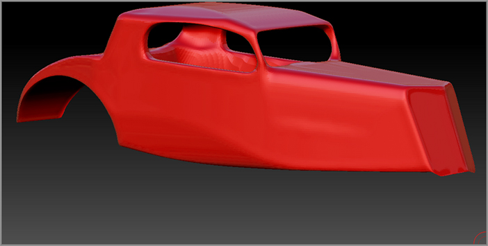
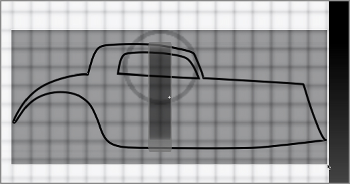
Now that you have the basics of ShadowBox down, let’s look at how you can use ShadowBox to create a sculptable mesh. The goal is to create the body for a hot rod (see Figure 5-9). It’s tempting to jump right in and start roughing out the shape for the body inside ShadowBox, but it might be helpful to first create a guide within ShadowBox that can be used as a reference for the shape of the masks.

Figure 5-9: Image of the hot rod body

c05f009.tif

The ShadowBox256.ZTL tool has a texture applied to it. This texture is a grid pattern with labels that helps you understand how ShadowBox is arranged while you create your reference images. The grid pattern is aligned so that you can easily find the center of each side of the box. You can see how the grid texture is applied by opening the Texture Map subpalette of the Tool palette (see Figure 5-10).

Figure 5-10: A grid texture is applied to the ShadowBox256.ZTL tool.

c05f010.tif

Follow these steps to create a hot rod reference image for ShadowBox:

1. In the UV Map subpalette of the Tool palette, click the Morph UV button, as shown in Figure 5-11. This unfolds the ShadowBox tool so you can see how the texture corresponds to the sides of the ShadowBox tool.

Figure 5-11: Click the MorphUV button in the UV Map subpalette of the Tool palette.

c05f011.tif
UV Texture Coordinates
UV texture coordinates (or UVs for short) are a set of coordinates used to tell 3D software how to map a 2D image onto the faces of a 3D object.
2. In the UV Map subpalette of the Tool palette, click the Morph UV button again, and ShadowBox reforms back into the cubical shape.

The texture that is applied to ShadowBox is an image file. This image is found in the ZBrush 4R3ZTools folder. The name of the texture file is SBRef.PSD. This image file can be opened in your favorite digital painting program and used to place reference images. Just make sure you save the altered image file under a different name so that you don’t overwrite the existing SBRef.PSD file.

3. You can exit ZBrush and open the SBRef.PSD image in your favorite painting program.

Figure 5-12 shows the reference image I created in Corel Painter. You can create a similar image using Photoshop or your favorite image-editing program. I created very simple silhouettes of the front, side, and top view of the hot rod body.

4. When you’re happy with the reference image, save it as a BMP file to your local drive. Go back into ZBrush and make sure the ShadowBox256.ZTL tool is loaded on the canvas, and the Edit button on the top shelf is on.
5. Open the Texture palette and click the Import button. Find the saved reference image on your local drive and load it into ZBrush.

Figure 5-12: The reference image for the body of the hot rod is painted in Corel Painter.

c05f012.tif
6. To apply the reference image to the ShadowBox, open the Texture Map subpalette of the Tool palette, expand the texture fly-out library by clicking the large gray icon box, and select the texture as shown in the top of Figure 5-13. The Texture On button should activate automatically; if it does not, click it and you’ll see the texture appear on the ShadowBox tool (bottom of Figure 5-13).
7. In the Tool palette, save the tool as hotRodSB.ZTL. The texture will be saved with the tool. Save the file in the Pixologic/ZTools folder so that it appears in Light Box.

Now you have a guide for creating the hot rod. You can use the reference I created if you’d like. Copy hotRodRef.BMP from the Chapter 5 folder on the DVD. The next step is to start roughing out the forms of the body by painting masks in ShadowBox.

Figure 5-13: Select the imported texture by clicking in the Texture subpalette of the Tool palette (top image). The reference image of the hot rod is applied to the ShadowBox tool (bottom image).

c05f013.tif
Reference Imagery
Finding reference images for a project is not too hard as long as you have an Internet connection and some time to search the web. However, sometimes finding the exact image you need for a particular detail can be particularly difficult. This is why I always keep a camera on me; you never know what you might stumble across while wandering out in the wild. I accidentally came across these hot rods at a highway rest stop while on vacation in New Zealand. Who knew Kiwis loved cars so much! On a separate occasion I came across this bizarre engine design that powered a homemade hot rod that was parked in a convenience store lot on Sunset Boulevard in Los Angeles.
c05uf002.tif

Create the Car Body in ShadowBox

Now you’re ready to start working on the car body. When approaching a shape such as this one, think about how you might carve the body of the car out of a piece of wood. You’ll start by creating an overall block for the car and then whittling down each side using the Mask brushes:

1. Load the hotRodSB.ZTL tool into ZBrush, and make sure that it is on the canvas and that the Edit button on the top shelf is activated. This tool is available in the Chapter 5 folder of the DVD.

Figure 5-14: Activate Local Symmetry so that the brush tips are aligned symmetrically on either side of the center line of the reference.

c05f014.tif
2. Make sure the Persp button on the right shelf is off. It will be easier to create masks in ShadowBox if Perspective mode is off.
3. Rotate the view of the ShadowBox tool so that you can see the plane labeled Back, and then click the Frame button on the right shelf (hotkey = F) to center the view. Turn on the Transp button on the right shelf so you’ll be able to see the reference images through the mesh generated in ShadowBox. Make sure Ghost is on as well. The Ghost transparency style is easier to use in ShadowBox than the standard transparency style.
4. Scale up the view of ShadowBox so that you can clearly see the reference image. Press X to activate Symmetry. Hold the brush over the ShadowBox tool. You should see two red dots indicating that Symmetry is activated along the x-axis (see Figure 5-14).
5. The two dots should meet at the center line in the middle of the back plane. If they do not, you’ll need to press the LSym button on the right shelf to activate Local Symmetry.
6. Open the sculpting brush fly-out library on the left shelf. Press the M key and then the R key to select the MaskRect masking brush. A warning will appear reminding you that this brush is active only while you hold the Ctrl key (Figure 5-15). Click OK.

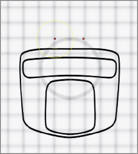
Figure 5-15: The MaskRect brush is automatically mapped to the Ctrl key.

c05f015.tif
7. Hold the Ctrl key and open the stroke type fly-out library on the left shelf. Click the Center button, as shown in Figure 5-16. Now whenever you draw a rectangular mask using this brush, the mask will be created from the center of the brush stroke.

Figure 5-16: Turn on Center in the options within the stroke type library.

c05f016.tif

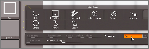
Figure 5-17: Hold the Ctrl key and drag from the center of the reference to create a rectangular mask that covers the reference image.

c05f017.tif
8. Hold the brush over the ShadowBox tool. You want to place the brush stroke roughly at the center of the front view of the reference image.
9. Hold the Ctrl key and drag out from the center to create a rectangular mask that covers the front view (see Figure 5-17). Don’t worry too much about being absolutely precise; you’ll be reshaping the rectangle in the next section.
10. Let go of the brush and you’ll see a gray transparent box appear. This is the ShadowBox mesh. The next step is to whittle the shape down a little to refine it.

Using the MaskCurve Brush

To shape the front view, you can use the MaskCurve brush. The MaskCurve brush uses the Curve stroke type. This means that you use the brush to draw out a curve to define the mask. This can make your masking very precise.

To whittle down the rectangular mesh you created in the previous section, you’ll actually be using the MaskCurve brush to erase parts of the mask drawn on the back of ShadowBox. This means that you’ll hold the Alt key before releasing the masking brush.

Before you try it out, here’s a little background on how the MaskCurve brush works. You’ll draw the curve by holding the Ctrl key and dragging on the canvas. You’ll see a dashed line appear as you drag. The curve starts at the point where you initially touch the canvas, and it will be a straight line as you draw it. One side of the curve is shaded with a gray gradient. This indicates which side of the curve will be masked. If you start the curve and then drag to the right, the shaded area appears on the top; if you start the curve and drag to the left, it appears on the bottom.

To make the line curved rather than straight, you add a point and then continue dragging. The point pins down a section of the curve, and then you can bend the line from there. To add a point to the curve, press the Alt key; to add a sharp corner, press the Alt key twice.

Once you release the mask by lifting the pen from the tablet (or releasing the mouse button if you’re using a mouse), the area on the shaded side of the line becomes masked, and thus a mesh is created. The mask will extend all the way to the edge of the ShadowBox and so will the mesh. The following steps show how you use this technique to shape the front profile of the hot rod:

1. Open the sculpting brush fly-out library and switch the masking brush to the MaskCurve brush. This brush will now be mapped to the Ctrl key. Click the Skip Warning Until Next Restart button so you don’t see the warning every time you switch masking brushes.
2. Let’s take a little off the top. Hold the brush to the left of the reference image, near the top but outside of the area that has already been masked. Press the Ctrl key and drag out toward the right, as shown in the left image in Figure 5-18. Drag all the way past the center and outside of the original rectangular mask. The idea is that you’ll be lopping off the corner of the rectangular mask.
3. Before you let go of the brush, press and hold the Alt key (it’s OK to let go of the Ctrl key at this point). The dashed curve will turn white, indicating that you’re in Erase mode.
4. Release the brush by lifting your pen from the tablet. The corners of the mask will disappear. Since Symmetry has been enabled, the corner on the other side will also disappear (see the right image in Figure 5-18).

Figure 5-18: Drag the MaskCurve brush out at an angle from left to right (left image). Release the stroke to cut off part of the top of the mask (right image).

c05f018.tif
5. If instead you see two long masks shooting out at an angle, then you forgot to hold the Alt key or you let go before pressing the Alt key. This is an easy mistake to make. Just press Ctrl+Z to undo and try again.
6. To chop off any extra mask on the top, start the mask from the left side and drag toward the right. Hold the Alt key and then release to erase the little peak from the top of the mask (Figure 5-19).

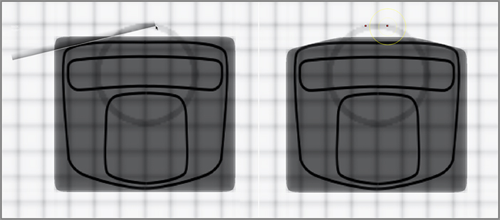
Figure 5-19: Use the MaskCurve brush to remove the very top of the mask.

c05f019.tif

Once you get the hang of refining the shape of the mask using straight lines, you can try using a curved line. To make a bend in the curve, press and release the Alt key while dragging out the curve. To make a sharper corner, press and release the Alt key twice.

7. Use Figure 5-20 as a guide for shaping the sides of the mask. Don’t worry about detail at the moment; you just want to get a rough shape established. Sometimes it’s easier to use series of mask curves rather than try to make a single mask curve that follows the reference perfectly.

Figure 5-20: The MaskCurve brush is used to shape the mask so that it fits the shape shown in the reference image on ShadowBox.

c05f020.tif
8. When you’re satisfied with how the front looks, rotate the view so you can see the result.

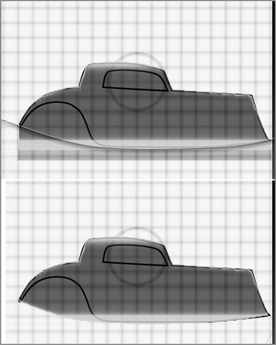
From the Perspective view, the mesh should look like a thick flat plane with angled corners, kind of like a piece of toast (see Figure 5-21). This is easier to see if you turn off the Transp button on the right shelf.

Figure 5-21: From a perspective angle the resulting mesh looks like a slice of toast.

c05f021.tif
9. Rotate the view so that you can see the side view clearly (remember to hold the Shift key after you start rotating the view in order to snap to a side view), and then scale up the view so that you can clearly see the profile of the car. Turn the Transp button on the right shelf back on if it has been turned off.
10. Use the MaskRect masking brush to create a rectangle that covers the general shape of the profile. In this case, it may be easier to turn off the Center option in the Stroke palette and drag the mask out from the upper-left corner of the profile (see Figure 5-22).

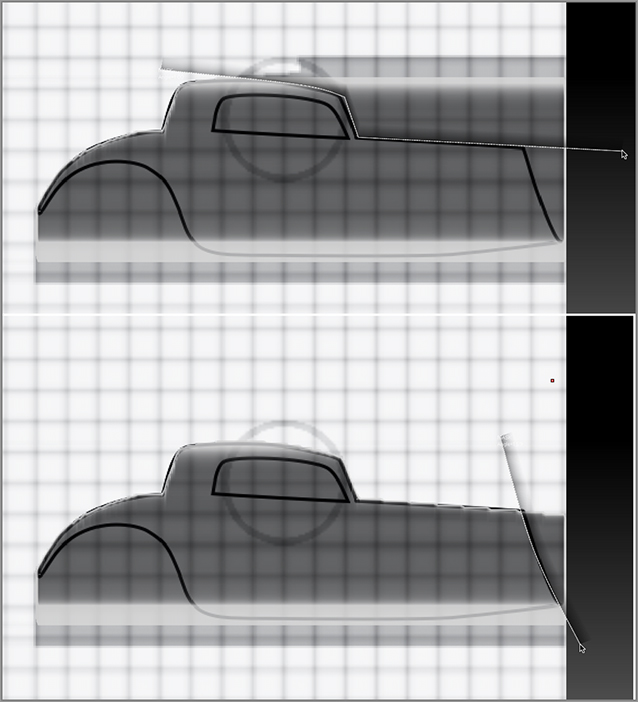
Figure 5-22: Draw a rectangular mask around the overall shape of the car body profile.

c05f022.tif

It doesn’t matter how tall the mask is, only how long it is. The resulting mesh will use the mask you’ve already created on the back side to constrain the height and width of the mask you create on the right side.

11. Once you have created the rectangular mask, switch back to the MaskCurve brush. You’ll use this brush again to whittle down the rectangular mask until it matches the profile of the car body.
12. Rotate the view a little so you can see what’s going on. Ctrl+Shift+click the plane that displays the right profile of the car body to isolate its visibility.
13. Rotate the view again so that you can see the profile.
ShadowBox Polygrouping
Before you start slicing up the mask, I’d like to point out a tip that will save you some headaches while working in ShadowBox. Each side of the ShadowBox is grouped separately, as shown in the following image. This means that you can hide all of the planes of the ShadowBox except the one you are currently working on. This is helpful because a mask drawn on one side of the box can easily spill over to one of the other sides, which will cause strange behavior in the mesh created at the center. This is especially true when using the MaskCurve stroke type.
c05uf003.tif
When you use the MaskCurve brush, the mask is generated on the shaded side of the curve, and the mask continues on to infinity out into space. So let’s say you use the MaskCurve to erase part of the mask near the back of the car. When you release the mask and then look at the mesh in Perspective view, the top part has been chopped off, ruining all the work you did on the front. This is because the mask shoots out from the curve and erases not only part of the mask on the right side but also part of the mask on the back side.
The solution to this problem is simple. Since each plane is a polygroup, just Ctrl+Shift+click the plane you need to work on and the other planes will be hidden. If part of the ShadowBox is hidden, the masking brush won’t affect it, so you won’t lose parts of your model. You can see this in the following image where the back side of ShadowBox has been hidden. Now the MaskCurve brush can easily be used on the side view of the car.
Remember that you can Ctrl+Shift+click a polygroup to isolate its visibility, Ctrl+Shift+click it again to invert visibility, and Ctrl+Shift+click on a blank part of the canvas to unhide everything.
c05uf004.tif

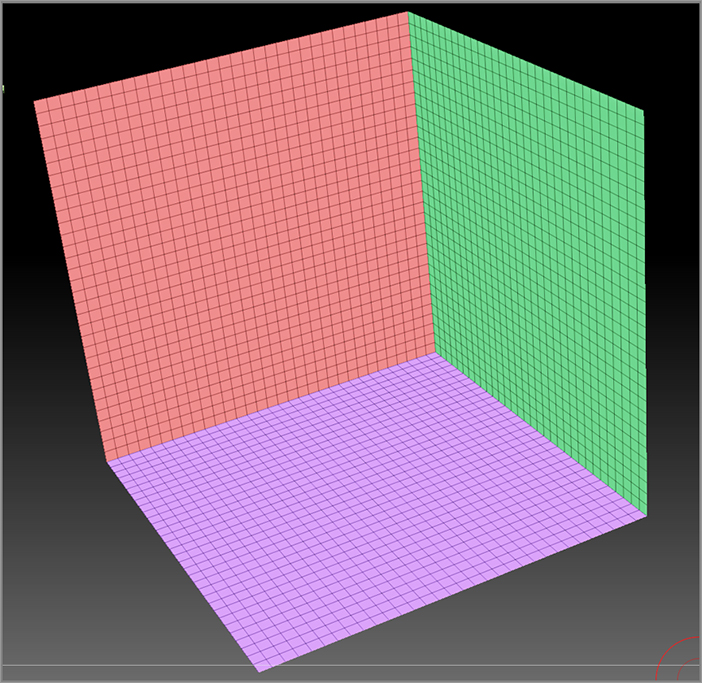
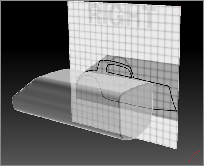
Figure 5-23: Draw the curve to match the shape of the trunk and the back of the car’s top.

c05f023.tif

You’ll continue to use the MaskCurve brush to work on the car, but now you’ll add points to the stroke’s curve so you can match the curves of the profile. You’ll start at the back of the car, work your way around the top toward the front, and then work back toward the wheel well. This will take several strokes; it’s not something you can do using a single curve.

To add a point to a curve, press and release the Alt key while dragging the curve out. Keep your curves as simple as possible.

14. Click near the back of the car and drag up toward the right along the curved edge of the rear of the car. Press and release the Alt key to add a point. Try to match the arc of the rear of the car. You should need to add only two points to match this curve in the reference image (see Figure 5-23, top).
15. When you reach the point where the rear trunk meets the back of the car’s top (where the rear window is), tap the Alt key twice. This adds two points on top of each other, allowing for a sharp corner. Drag the curve up past the top of the car (see Figure 5-24, middle image).
16. Press and hold the Alt key and release the masking brush. The resulting mask should match the back of the car. It may take a couple of tries at first until you get used to creating masking curves.
17. Create another curve to form the rounded back of the top (see Figure 5-24, bottom image).

Figure 5-24: The profile of the top of the car is formed by using the MaskCurve brush to cut out parts of the mask.

c05f024.tif

Now you can create a curve that forms the roof, windshield, and hood (see Figure 5-24).

Figure 5-25: Use the MaskCurve brush to refine the bottom edge of the car.

c05f025.tif
18. Finally, use a series of curves to refine the bottom. This time start each curve from the right and drag toward the left. The shaded side of the curve will face downward so that when you hold the Alt key and release the masking brush, the bottom parts of the mask will be erased. At this point, don’t worry about creating the wheel well (see Figure 5-25).
19. This is a good place to save the project. Click the Save As button in the File menu to save the project as HotRod_v01.ZPR.

Using the MaskCircle Brush

The MaskCircle brush simply creates the mask in the shape of an oval. This can be used to cut out the wheel well in the profile of the car. As with the MaskRect brush, you can activate the Center option so that the mask is created from the center of the stroke:

1. Continue with the project from the previous section.
2. Open the sculpting brush fly-out library and press M and then C to switch to the MaskCircle brush. Remember that this brush is active only while you hold the Ctrl key.
3. Hold the Ctrl key, open the stroke type fly-out library on the left shelf, and turn on the Center button.
4. Turn on the Square button as well. This means that the circle fits within a square area, so instead of being an oval it will be a perfect circle (see Figure 5-26).
5. Hold the Ctrl key and drag outward from the center of the circular area of the wheel well.

Figure 5-26: Turn on the Square and Center buttons in the stroke type fly-out library for the Mask Circle brush.

c05f026.tif
6. It’s usually impossible to get the mask perfectly placed the first time you drag it out, but this is an easy problem to solve. Before you release the mask, hold the spacebar. You can then move the mask around until you find the best position. This technique also works with the other type of mask brushes, such as MaskRect and MaskCurve.
7. Once you have the mask positioned, hold the Alt key and release. This will cut a hole into the mask in the shape of a circle (see Figure 5-27).
8. Once you have used the MaskCircle brush to cut out the wheel well, switch back to the MaskCurve brush and use the curve to try to make the mask match the reference image a little better (see Figure 5-28).
9. Save the project as HotRod_v02.ZPR.

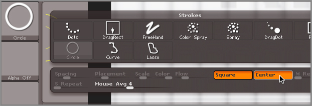
Figure 5-27: The MaskCircle brush is used to cut a circular hole for the wheel well.

c05f027.tif

Figure 5-28: The extra parts of the mask are trimmed away using the MaskCurve brush so that the mask matches the profile.

c05f028.tif

Creating the Top View of the Hot Rod

If you rotate the view of the ShadowBox, the mesh at the center looks a little jagged or “chunky.” That’s okay. As you create the final mask for the top view, you’ll see that the mesh becomes a bit smoother again. Here are the steps:

1. Continue with the project from the previous section or open the HotRod_v02.ZPR project you saved.
2. Rotate the view of the ShadowBox so that you can see the mesh. Hold Ctrl+Shift and click on a blank part of the canvas to unhide the rest of the box.
3. Hold Ctrl+Shift and click on the bottom plane of the ShadowBox tool to hide everything but the bottom.
4. Rotate the view so you can see the ShadowBox from the top. Press X to activate Symmetry.
5. Use the MaskRect brush to draw a rectangle around the top of the reference image. It’s easy to forget to do this, and then when you start to refine the edges, it seems as though nothing is happening. Don’t forget to first create a rectangular mask that covers the top view of the car, and then use the MaskCurve brush to shape the rectangular mask.
6. Use the MaskCurve brush to make the edges of the mask match the reference image. Use Figure 5-29 as a guide.
7. Save the file as HotRod_v03.ZPR.

Figure 5-29: Use the MaskCurve brush to trim the mask from the top view.

c05f029.tif

Using the MaskLasso Brush to Create Windows

To finish off the basic body of the hot rod, you can cut holes in the top for the windows. Using the MaskCurve brush won’t work because you can’t form a closed loop with the curve. Since the mask is created on one side of the curve, ZBrush won’t understand how to create the mask when you try to make a loop. Instead, you can use the MaskLasso brush:

Figure 5-30: Use the MaskLasso brush to create a window in the side view.

c05f030.tif
1. Continue with the project from the previous section or open HotRod_v03.ZPR.
2. Hold the Ctrl key and select the Mask Lasso brush. Remember that the brush is active only when you hold the Ctrl key.
3. Rotate the view of the hot rod so that you can see the right side.
4. Hold the Ctrl key and use the lasso to draw a shape roughly matching the window. Hold the Alt key before releasing the brush so that the mask is in Erase mode; otherwise nothing will happen when you let go of the brush (see Figure 5-30).
MaskLasso or MaskPen?
The great thing about having so many masking options is that you can choose whichever mask brush fits your own modeling style. If you find that the MaskLasso brush is hard to use, try switching to MaskPen. Using MaskPen, you can hold the Alt key and simply erase the window area on the ShadowBox plane. It’s really up to you which method you prefer.
5. Rotate the view of the ShadowBox so that you can see the back plane. Use the same technique to create the front windshield. Make sure Symmetry is active so that you only have to draw the mask on one side of the windshield (see Figure 5-31).
6. Click the Save As button in the File menu to save the project as HotRod_v04.ZPR.

Congratulations! You’ve created your first ShadowBox model. The next step is to use the clip brushes to refine the edges, but before you get to that you can use a few more tricks in ShadowBox to create hubcaps for the wheels.

Figure 5-31: Use the MaskLasso brush to create a window while facing the back plane of the ShadowBox.

c05f031.tif

Using Radial Symmetry in ShadowBox

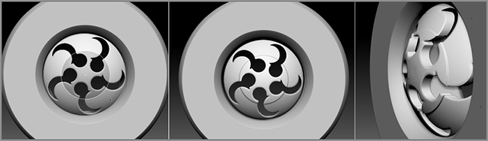
ShadowBox is a great way to explore shapes. Once you start to combine techniques, you can create some really interesting things. In this exercise, you’ll look at some approaches for creating stylish hubcaps for the hot rod:

1. Start a fresh ZBrush session. Open Light Box to the Tool section and double-click the ShadowBox128.ZTL tool. Draw it on the canvas and switch to Edit mode.
2. To make nice, crisp designs in ShadowBox, you’ll want to increase the resolution. In the Geometry subpalette of the Tool palette, turn the ShadowBox button off. This will make the Resolution slider available. Set the slider to 256.
3. Click the ShadowBox button to turn it back on. After a few seconds it will appear. It will likely be filled with a cubical mesh. Ctrl+drag on a blank part of the screen to clear the mask from the sides of the ShadowBox. This will make the cubical volume disappear.
4. In the material fly-out library on the left shelf, select the skinShade4 material so you can easily see the grid texture on the tool.
5. Turn off the Persp button on the right shelf, and turn on Transp and Ghost.
6. Click the Frame button on the right shelf to center the view of ShadowBox (hotkey = F).
7. Turn on the L.Sym button on the right shelf so that Symmetry will be in line with the center of the back view of the ShadowBox.
8. Expand the sculpting brush fly-out library, and press M and then C to switch to the MaskCircle brush.
9. In the stroke type fly-out library, make sure the Square and Center buttons are on so that you can easily draw a perfect circle. (The Square button just makes sure that the mask is perfectly round, that is, it fits into a square.)
10. In the Transform palette, turn on Activate Symmetry if it’s not on already. Turn on the >Z< button so that Symmetry is activated on the z-axis. Turn on the (R) button so that Radial Symmetry is active, and set RadialCount to 5 (see Figure 5-32).

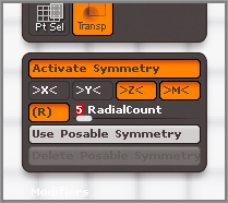
Figure 5-32: Turn on Radial Symmetry on the z-axis and set RadialCount to 5.

c05f032.tif

Using Radial Symmetry, you can easily find the exact center of the back view of the ShadowBox.

11. Hover the brush over the ShadowBox. You’ll see five red dots; these are the brush tips. Bring them toward the center until you see a single point. Hold the Ctrl key and drag outward to create a circular mask (the left image in Figure 5-33).
12. Let go of the brush to create the mask. The mesh at the center of the ShadowBox will be a circular disc (right image in Figure 5-33).

Figure 5-33: Use the five brush points to find the center of the back side of the ShadowBox. Create a circular mask from the center.

c05f033.tif

Now for the fun part. You can start to experiment with designs using Radial Symmetry. This can get a bit addictive.

13. Move the brush tip away from the center of the ShadowBox so that you see five red dots. Hold the Ctrl key and drag to create a circular mask. Make a small circle above the center. Hold the Alt key and release the brush to cut a circular hole into the mask (the left and center images in Figure 5-34). Five holes appear around the mask.
14. Create a second series of larger circles slightly offset from the first. The result is a nice “bat wing” design for the hubcap (the right image in Figure 5-34).

Figure 5-34: Circular masks are used to cut holes in the original mask. Using Radial Symmetry, you can easily create a pattern.

c05f034.tif

Experiment with different variations. You can try turning off the Square option in the stroke type fly-out library and use ovals. Try using the MaskRect brush. Add more or less detail if you want. Figure 5-35 shows a few variations using different masking techniques. Try making freeform shapes using the MaskLasso brush. Remember that you can hold the spacebar to reposition the mask before you release the masking brush.

Figure 5-35: Use a variety of mask brushes and Radial Symmetry to come up with alternate hubcap designs.

c05f035.tif

Using Alpha Textures within ShadowBox

You can apply alpha textures to the masking brush to create precise designs. These can be the alpha textures that come with ZBrush or even your own custom textures that you can create in paint programs such as Photoshop, Painter, and Illustrator. Follow these steps:

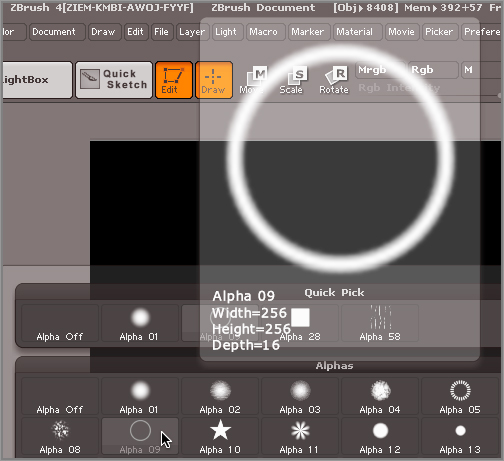
Figure 5-36: Select the MaskRect brush and choose Alpha 09.

c05f036.tif
1. Continue with the hubcap design you created in the previous section. Make sure Radial Symmetry is still active along the z-axis.
2. Open the sculpting brush fly-out library and press M and then R to switch to the MaskRect brush. This is the best masking brush to use when you want to apply alpha textures to the ShadowBox. (Don’t confuse this stroke type with the DragRect brush. You can use DragRect, but the alpha will be blurry and the resulting mesh will not be as well defined).
3. Open the alpha texture fly-out library on the right shelf and choose Alpha 09. This is a simple circle alpha (see Figure 5-36).
4. Hold the Ctrl key and drag out across the back of the ShadowBox, and then release the brush to create the mask (see Figure 5-37).

Try variations to see what kind of designs you can create with this texture. You can also click the Import button in the Alpha palette to import your own alpha textures, as shown in Figure 5-38. The textures you import must be grayscale textures saved in TIFF, Photoshop, or BMP format.

Figure 5-37: Using an alpha texture with the MaskRect brush allows you to add complexity to your hubcap design.

c05f037.tif

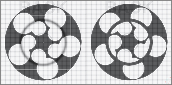
Figure 5-38: You can import custom alpha textures to create even more complex designs.
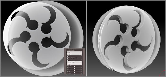
c05f038.tif

MatchMaker Brush

The purpose of the MatchMaker brush is to make one surface conform to another. For example, you can round the shape of the hubcap so that it’s no longer a flat piece by using Match Maker to push the surface against a PolySphere. In this section you’ll do just that. The technique is very easy to use and a lot of fun:

1. Open the HubCap_v01.ZTL tool from the Chapter 5 folder on the DVD. Draw the hubcap tool on the canvas and switch to Edit mode (hotkey = T).
2. The hubcap is currently still a ShadowBox object. Open the SubTool subpalette of the Tool palette and turn the ShadowBox button off. Now the hubcap is a mesh that you can sculpt with any of the sculpting brushes (see Figure 5-39).

Figure 5-39: The hubcap is now a sculptable mesh.

c05f039.tif

You’ll need a round surface to act as a template for the MatchMaker brush. A slightly flattened PolySphere should work just fine.

3. Open Light Box to the Tool section and double-click the PolySphere to load it into ZBrush. The canvas will automatically switch to the PolySphere in Edit mode. Don’t worry if the hubcap disappears; it is still available in the Tool palette.
4. Open the SubTool subpalette of the Tool palette and click the Append button. Choose the hubcap to append it to the PolySphere.
5. On the right shelf, click the Transp button and rotate the view. You should see the hubcap appear as a transparent object inside the PolySphere.
6. Chances are the hubcap and the PolySphere are not aligned very well (Figure 5-40). There is a quick way to fix this. Select the hubcap in the SubTool subpalette of the Tool palette. Expand the Deformation subpalette of the Tool palette, and click the Unify button at the top.

Figure 5-40: The hubcap is out of alignment with the PolySphere tool.

c05f040.tif

The MatchMaker brush pushes the selected subtool up against the other visible subtools to make the surfaces conform. For it to work properly, there should be no empty space behind the selected subtool, so the PolySphere needs to be scaled up a little so that the edges of the hubcap don’t get distorted (see Figure 5-41).

Figure 5-41: If there is empty space behind the subtool, the Match Maker brush will not function properly.

c05f041.tif
7. In the SubTool subpalette of the Tool palette, select the PolySphere subtool. Expand the Deformations palette. Click the Size deformer slider so that the numeric value appears highlighted in red. Type the number 10 and press Enter. You’ll see the PolySphere grow slightly so that now the hubcap easily fits inside.
8. Rotate the view of the PolySphere and hubcap so that you can see them from the side. In the Deformations subpalette, click the x and the y letters to the right of the Size slider to turn off these axes. Drag the Size slider all the way to the left; this will flatten the PolySphere a little (see Figure 5-42, left image).

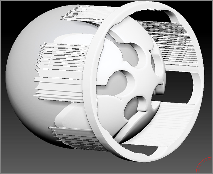
Figure 5-42: The PolySphere is flattened and moved to the left of the hubcap in the side view. From the front view the hubcap is ready to be pressed against the PolySphere with the MatchMaker brush.

c05f042.tif
9. In the Deformations subpalette of the Tool palette, turn off the x and y buttons for the Offset deformer. Drag the Offset slider to the right until the PolySphere appears to the left of the hubcap (see Figure 5-42, middle image).
10. Switch to the HubCap subtool and rotate the view so that you can see the hubcap straight on from the front (see right image in Figure 5-42). Turn off the Transp button on the right shelf.
11. Open the sculpting brush fly-out library. Press M and then M again to switch to the MatchMaker brush (see Figure 5-43).

Figure 5-43: The MatchMaker brush is selected in the sculpting brush library.

c05f043.tif
12. On the top shelf, make sure the Zsub button is on. Set Z Intensity to 40. At this strength you’ll be able to deform the hubcap against the PolySphere while still having a fair amount of control.
13. Turn off Symmetry (hotkey = X). Position the brush at the center of the hubcap and then drag outward. You’ll see the hubcap change, although it won’t be clear what’s happening until you’ve finished.
14. Once you’ve dragged all the way out past the edge of the hubcap, let go of the brush and rotate the view. You’ll see that the hubcap now appears rounded, matching the surface of the PolySphere. The design on the hubcap has been preserved (see Figure 5-44).

Figure 5-44: The hubcap appears rounded after using the MatchMaker brush.

c05f044.tif

The MatchMaker brush is extremely useful and versatile. In the Tool section of Light Box, you’ll find several example tools named MatchMaker1.ZTL, MatchMaker2.ZTL, and so on. These have been set up for you to experiment with.

15. In the SubTool subpalette of the Tool palette, select the PolySphere subtool. Click the Delete button at the bottom of the SubTool subpalette to remove the PolySphere. Click the Save As button in the Tool palette to save the tool as HubCap_v02.ZTL.

Clip Brushes

The ZBrush clip brushes are particularly well suited for hard-surface modeling, and, among their many possible applications, they do a good job of refining the edges of meshes created in ShadowBox.

Clip brushes use the same stroke types as the masking and selection brushes—namely the rectangular, circle, lasso, and curve stroke types. They are used to slice away parts of the surface, but it is important to understand that they don’t actually delete geometry; rather, they squash the selected polygons so that they conform to the selected shape. Imagine taking a lump of clay and squashing it down on a flat surface; that’s the basic idea behind how clip brushes work. Clip brushes work really well when combined with Dynamesh as a way to create hard-surface objects. After you flatten an edge with a clip brush, you can then “dynamesh” the surface, which will eliminate the “squished” polygons and rebuild the topology of the surface while retaining the hard edges.

In the following exercises, you’ll get a taste for the kinds of things you can do with these brushes, but the creative possibilities stretch far beyond this simple introduction. Let’s start by trying the brushes out on a PolySphere.

Clip Brush Basics

There are a few rules you have to be aware of when using the clip brushes. An understanding of these rules will help you make sense of how the brushes work. Clip brushes are automatically mapped to the Ctrl+Shift hotkey, just like the selection brushes. When you choose ClipCircle, ClipCircleCenter, ClipCurve, or ClipRect, you’ll get a warning that lets you know that these brushes are activated by holding Ctrl+Shift together. Be aware that both the clip brushes and the selection brushes share the Ctrl+Shift hotkeys.

This example demonstrates the basics of using the clip brushes.

1. Start a fresh session of ZBrush, open Light Box to the Tool section, and double-click the PolySphere.ZTL tool. Make sure the tool is on the canvas and that Edit mode is enabled on the top shelf.
2. From the material fly-out library, choose the skinShade4 material.
3. On the right shelf, activate the PolyF button (hotkey = Shift+F) so that you can see the wireframe display on the polygons.
4. Open the sculpting brush fly-out library and press C and then R to choose the ClipRect brush. A warning appears reminding you that this brush is activated by holding Ctrl+Shift together (see Figure 5-45). Click the Skip This Note Until Next Restart button so that the next time you choose a Clip brush, you don’t see the warning.

Figure 5-45: The ClipRect brush is assigned to the Ctrl+Shift hotkey combination.

c05f045.tif
5. Make sure Symmetry is disabled.
6. Hold Ctrl+Shift and drag the rectangular shape over the top two-thirds of the PolySphere (see Figure 5-46, left image). When you release the brush, it appears as though the bottom has been chopped off (see Figure 5-46, middle image).

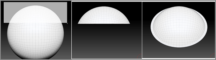
Figure 5-46: The ClipRect brush squashes all the polygons outside the rectangular selection so that they fit within the selection area.

c05f046.tif
7. Rotate the view and zoom in so that you can see the bottom. You can see that the polygons have not been deleted; they’ve just been flattened (see Figure 5-46, right image).

All the polygons outside the selected area are pushed up so that they fit within the rectangular selection.

8. Press Ctrl+Z to undo the last action. The PolySphere should return to its rounded state.
9. Now hold Ctrl+Shift and select just the upper third of the PolySphere (see Figure 5-47, left image).

The bottom two-thirds disappear, but notice that when you rotate the view, you can see what appears to be a flattened lip around the edge of the remaining section (see Figure 5-47, right image). This is because the lower two-thirds are pushed straight up to meet the outer edge of the selection rectangle, but they are not pushed inward toward the center. This creates a flattened rim. When using the clip brushes, keep this in mind.

Figure 5-47: The top third is selected using the ClipRect brush, but this leaves a very thin lip around the edges of the selected area.

c05f047.tif

Holding the Alt key inverts the selection so that polygons within the selected area are pushed out of the selected area. Be careful when using this technique with the ClipRect brush because it usually creates very strange results (see Figure 5-48).

Figure 5-48: Holding the Alt key before releasing the ClipRect brush inverts the clipping action but can cause some odd results.

c05f048.tif

You can use the Square option in the stroke type fly-out library to make the selected area a perfect square and the Center option so that the selection starts at the center of the stroke rather than at the corner. To turn these on, hold Ctrl+Shift and open the stroke type fly-out library on the right shelf. Click the Square and Circle buttons.

You can reposition the selection area before you release the brush. Just hold the spacebar and drag on the canvas. This allows you to precisely position the clipping area.

Using the ClipCircle Brush

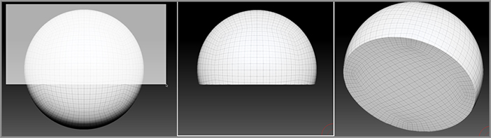
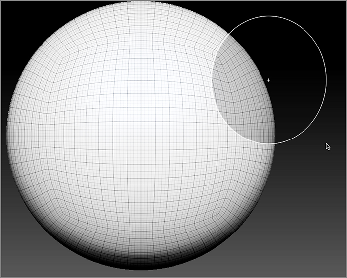
The ClipCircle brush works just like the ClipRect brush except that the selection area is circular:

1. Press Ctrl+Z to undo any changes you’ve made to the PolySphere.
2. Open the sculpting brush fly-out library and choose the ClipCircle brush.
3. Hold Ctrl+Shift and drag an oval over the top two-thirds of the PolySphere. Release the brush.

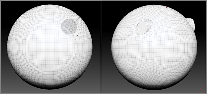
Just as with the ClipRect brush, the area outside the selection is clipped away. When you rotate the view, you can see how the polygons outside the circular selection are pushed up to match the edges of the circle (see Figure 5-49).

Figure 5-49: The ClipCircle brush clips away everything outside of the circular selection area.

c05f049.tif
4. Press Ctrl+Z to undo the last action.
5. Press Ctrl+D twice to add two more subdivisions to the PolySphere.
6. Hold Ctrl+Shift and drag a small circular selection on top of the PolySphere. Hold the Alt key and release.

The result is strange but also kind of interesting. The polygons are pushed out of the selected area as much as possible, resulting in a flattened circular plane within the PolySphere. This can be used for interesting details (see Figure 5-50). This kind of detail is perfect for robotic or mechanical details. Notice that the wireframe on the PolySphere shows how this technique distorts the topology of the surface.

Figure 5-50: Hold the Alt key before releasing the ClipCircle brush on a small section of the PolySphere to create interesting details.

c05f050.tif

The ClipCircleCenter brush is just like the ClipCircle brush except that the Center and Square options in the stroke type fly-out library are already enabled.

7. Spend a few minutes experimenting with the ClipCircle and ClipRect brushes. They take a little practice to get used to. As you’ll soon discover, they are great tools for creating crisp edges and details for hard-surface models.
Clip Brush Center
At the center of the clip brush boundary, you’ll see a little plus sign indicating the center of the selection area. When using the Clip Circle brushclip brush and the Alt key together to cut away part of a surface, you’ll get better results if the plus sign remains outside the mesh.
c05uf005.tif

Creating a Tire Using Clip Brushes

Now let’s get some practice using these techniques to create a tire for the hot rod. You’ll use the ClipRect and ClipCircle brushes to shape a torus into a tire:

1. Start a fresh session of ZBrush.
2. In the Tool palette, open the tool fly-out library and select the Ring3D tool. Draw the tool on the canvas and switch to Edit mode.

The Ring3D tool is a parametric 3D tool, meaning that it can’t be edited using the sculpting brushes—including the clip brushes. You can convert it into a polymesh object, but first you can establish a few settings just to thicken it up a little.

3. At the bottom of the Tool palette, expand the Initialize subpalette.
4. Set SRadius to 60. Set SDivide to 40 and LDivide to 80 (see Figure 5-51).

Figure 5-51: Set SRadius and the divisions in the Initialize palette.

c05f051.tif
5. At the top of the Tool palette, click the Make PolyMesh 3D button. At this point the object has been converted into a sculptable mesh.
6. In the material fly-out library, choose the Basic material.
7. Press Ctrl+D twice to add two levels of subdivision to the mesh.
8. Rotate the view of the tire so that you can see it from the side, as shown in the left image in Figure 5-52.
9. In the Transform palette, turn on the Activate Symmetry button. Turn the >Z< button on and the >X< button off so that symmetry is created along the z-axis.
10. Hold Ctrl+Shift and drag out a selection box starting from the right and moving to the left. The box should cover most of the torus, as shown in the middle image of Figure 5-52. Release the brush. The tire will be flattened on both sides because Symmetry has been activated, as shown in the right image of Figure 5-52.

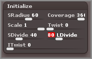
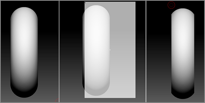
Figure 5-52: The ClipRect brush is used to flatten the sides of the tire.

c05f052.tif

Next you’ll use the ClipCircleCenter brush to flatten the area of the tire tread. However, it can be a little tricky to find the center of the tire since there’s a big hole at the center. Using Radial Symmetry can help with this problem.

11. In the Transform palette, turn on Radial Symmetry and set Radial Count to 16. Remember that to turn on Radial Symmetry you need to first activate Symmetry (hotkey = X) and then turn on the R button in the Transform palette.
12. Rotate the view of the tire so that you can see it from the front.
13. From the sculpting brush library, choose the ClipCircleCenter brush.
14. Hold Ctrl+Shift and drag out from the center of the tire. Drag just so the edge of the selection circle is about halfway between the flattened edge of the tire and the outer edge, as shown in the left image of Figure 5-53.

Figure 5-53: The edges of the tire are flattened using the ClipCircleCenter brush.

c05f053.tif
15. Before you release the brush, hold the spacebar and move the selection circle. Try to center the selection with the tire as well as you can. Radial Symmetry will ensure that the clipping remains fairly circular.
16. Let go of the clipping brush to flatten the outer edge of the tire (see Figure 5-53, right image).
17. Repeat steps 14 and 15, but this time align the selection brush with the inner edge of the flattened side of the tire. Once it’s aligned, drag back toward the center.
18. Hold the Alt key and release the brush. This will flatten out the inside edge of the tire. This is a little tricky and may take you a couple tries to get perfect (see Figure 5-54).

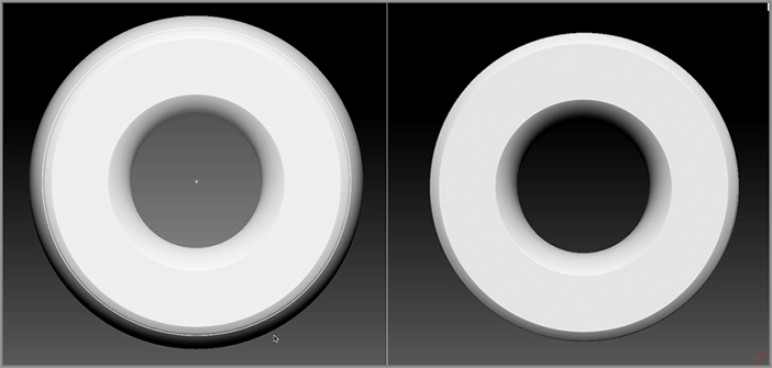
Figure 5-54: The inside edge of the tire is flattened using the ClipCircleCenter brush.

c05f054.tif
19. If you want to make the tire a little wider, expand the Deformations palette, turn off the x and y buttons to the right of the Size slider, and move the slider to the right.
20. Click the Save As button in the Tool palette to save the tool as tire_v01.ZTL.

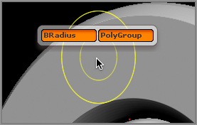
Brush Radius and PolyGroup Clip Brush Options

You can activate two options that affect how the brushes clip the surface: Brush Radius and PolyGroup. The Brush Radius option constrains the size of the clipping based on the current radius of the brush. The PolyGroup option automatically divides the object into polygroups based on the clipped areas. These options are found in the Clip Brush Modifiers subpalette of the Brush palette. In this section you’ll use these options to add a little detail to the hubcap.

1. Continue with the tire model you created in the last section or open the tire_v01.ZTL tool.
2. Open HubCap_v02.ZTL, which you created earlier in the chapter, using the Load Tool button in the Tool palette.
3. In the SubTool subpalette of the Tool palette, click the Append button. Choose the tire_v01.ZTL tool from the fly-out tool library to append it to the hubcap.
4. Turn on the Transp button on the right shelf. Expand the Deformation subpalette of the Tool palette.
5. Make sure the x, y, and z buttons are all active to the right of the Size slider. Move the slider to the left to scale down the hubcap so that it fits within the center of the tire (see Figure 5-55).

Figure 5-55: The hubcap is scaled down to fit within the tire.

c05f055.tif
6. Rotate the view of the tire to the side. In the Deformations subpalette of the Tool palette, turn off the x button next to Offset and turn on the z button. Move the slider to the left to move the hubcap out a bit (see Figure 5-56).

Figure 5-56: The hubcap is moved out from inside the tire.

c05f056.tif
7. Turn off the Transp button.
8. Hold Ctrl+Shift. In the sculpting brush fly-out library on the right shelf, select the ClipCircle brush. Turn on Radial Symmetry on the z-axis for the hubcap if it’s not already on.
9. Set the Draw Size slider on the top shelf to 10.
10. Rotate the view of the tire so that you can see the hubcap face on. Position the brush at the center of the hubcap.
11. Open the Brush palette and expand the Clip Brush Modifiers subpalette; turn on both the BRadius and the PolyGroup buttons, as shown in Figure 5-57.

Figure 5-57: Turn on the BRadius and PolyGroup button.

c05f057.tif
12. Hold Ctrl+Shift and drag outward from the center, as shown in left image in Figure 5-58.
13. Hold the Alt key and release the brush. This creates a groove in the hubcap (see Figure 5-58, center and right images).

Because the BRadius option is on, the size of the clip is restricted by the Draw Size setting on the top shelf. This is a great technique for creating hard-surface details such as grooves.

14. Turn on the PolyF button on the right shelf. You’ll see that the face of the hubcap is now divided into polygroups based on the clipped area.
15. Save the tool as wheel_v01.ZTL. Save it to the ZBrush 4/ZTools folder so that it appears in the Tool section of Light Box.

Figure 5-58: Create a circular selection with the clip brush. A groove is created in the hubcap because the BRadius option is on.

c05f058.tif
Clip Brush Options Hotkey
If you’re using a clip brush you can access the BRadius and PolyGroup options by holding the spacebar. This means you’re holding the Ctrl+Shift keys and the spacebar all at the same time. A little pop-up menu appears on the canvas that lets you turn these options on or off.
c05uf006.tif

Using the ClipCurve Brush

The ClipCurve brush uses a curve stroke type and is similar to the MaskCurve brush except that instead of masking an area, it clips it so that all the polygons on the shaded side of the curve are squashed to match the shape of the curve. The ClipCurve brush is great for designing complex surfaces and also works well for refining the meshes you make with ShadowBox.

Let’s take a look at how the ClipCurve brush works by trying it out on a PolySphere:

1. Start a fresh session of ZBrush, open Light Box to the Tool section, and double-click the PolySphere.ZTL tool. Make sure that the tool is on the canvas and that Edit mode is enabled on the top shelf.
2. From the material fly-out library, choose the skinShade4 material.
3. On the right shelf, activate the PolyF button so that you can see the wireframe display on the polygons.
4. Open the sculpting brush fly-out library and press C and then C again to choose the ClipCurve brush. If this is a new session of ZBrush, you’ll see the familiar warning advising you that the brush is mapped to Ctrl+Shift.
5. Hold the Ctrl and Shift keys and start a curve above and to the right of the PolySphere. Drag out a straight line that goes down past the right corner of the center of the PolySphere. The shaded side of the curve should be on the right of the curve line.
6. Release the brush. You’ll see that the side of the PolySphere is now flattened (see Figure 5-59). The clipping action goes all the way through the surface in a direction that is perpendicular to the canvas.

Figure 5-59: The surface is clipped on the right, the shaded side of the curve.

c05f059.tif
Curve Snapping
You need to hold Ctrl+Shift only long enough to activate the brush and start the curve. Once the curve is started, you can let go of Ctrl+Shift. If you continue to hold the Shift key, the curve will snap to specific angle increments. This can be helpful in creating precise curves, but it can be confusing when you’re just getting the hang of using the brush. If you notice that the curve is snapping from one angle to the next, let go of the Ctrl+Shift keys.
7. Press Ctrl+Z to undo and return the PolySphere to its unclipped state.
8. Now start a curve below and to the left of the center of the PolySphere; this time drag upward.
9. As you drag the curve up through the PolySphere, press the Alt key to add a point, and then change directions as you drag to make a curve. Add a few more points and then let go. The PolySphere is clipped so that it matches the curve (see Figure 5-60).

Figure 5-60: The clipped surface matches the contour of the curve.

c05f060.tif

There is a limit to the types of curves you can create. A curve that loops around will mangle the surface or create unpredictable results. Remember that all the polygons of the surface are squashed against the form of the curve in a straight line, so if the curve loops around, ZBrush will have a hard time clipping the surface (see Figure 5-61).

Figure 5-61: Complex curves cause unpredictable results when using the clip brush.

c05f061.tif

It’s also important to pay attention to which side of the curve is shaded. If you drag the curve downward, the shaded side will be on the right; if you drag upward, the shaded side will be on the left. If you drag from right to left, the shaded side will be on top, and from right to left, the shaded side will be on the bottom. The shaded side is the clipping side. Holding the Alt key inverts the function of the brush so that the unshaded side becomes the clipping side. While you are first getting used to the way the brush works, avoid using the Alt key. Once you get the hang of it, you can start experimenting with using the Alt function.

If you need to reposition the curve, hold the spacebar and drag before releasing the brush. This is very helpful because it can be hard to draw the curve exactly where you want it on the first try. Typically you’ll create a curve, then hold the spacebar and reposition the curve, and then let go. After a little practice this becomes somewhat second nature.

10. Press Ctrl+Z to undo and return the PolySphere to its unclipped state. Press X to activate Symmetry along the x-axis.
11. Rotate the view of the PolySphere so that you can see two red dots when you hold the brush over the surface.
12. Use the ClipCurve brush to create a curving line down the right side of the surface. Release the brush. The surface is clipped symmetrically on both sides (see Figure 5-62).

Figure 5-62: The surface is clipped symmetrically along the x-axis.

c05f062.tif

Using Symmetry with the clip brush, you can create some really interesting shapes, but be aware that if you draw a curve that crosses over the center while Symmetry is enabled, you’ll get some strange results because the clipping action of one curve will overlap the area clipped by the symmetry (see Figure 5-63). Try using Radial Symmetry with the curve to create an interesting shape (see Figure 5-64).

Figure 5-63: Curves that overlap the center point of the surface while Symmetry is enabled can cause unpredictable results.

c05f063.tif

Figure 5-64: Use Radial Symmetry to create interesting shapes.

c05f064.tif

There is no ClipLasso brush in the Brush palette, but you can use the Lasso stroke type with the clip brushes. To select this stroke type, select one of the clip brushes and then, while holding Ctrl+Shift, open the stroke type fly-out library and choose Lasso.

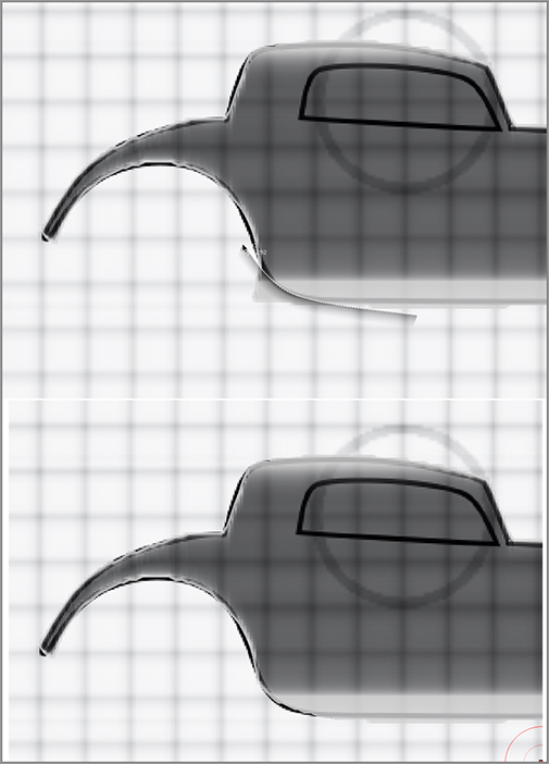
Refining the Car Body Using Clip Brushes

In this section, you’ll get some hands-on experience using the ClipCurve brush to neaten up the edges of the hot rod car body created in ShadowBox. The general idea is to use the brush to refine the edges and prepare the model for detailing with the sculpting brushes. Here are the steps:

1. Click the Open button in the File menu to open the HotRod_v04.ZPR project you created earlier in this chapter.
2. At this point the body is still a ShadowBox tool. Expand the SubTool subpalette of the Tool palette and turn off the ShadowBox button to convert the mesh into a surface that can be sculpted.
3. Make sure the Persp button on the right shelf is off. The brushes work best when the tool is not in Perspective mode.
4. Rotate the view so that you can see the model from the side view. Open the sculpting brush fly-out library and press C and then C again to select the ClipCurve brush.
5. Scale up the view so that you are zoomed in to the car’s roof. You’ll use the curve to refine the back of the car’s top.
6. Hold Ctrl+Shift and start a curve by clicking to the left of the car, as shown in the left image of Figure 5-65.
7. Let go of Ctrl+ Shift but drag the curve up to the right. Press the Alt key to add a bend in the curve. You want to create a curve that matches the shape of the top of the car. At the moment it’s OK to draw the curve away from the car (see Figure 5-65, left image).

Figure 5-65: Draw the clip curve to match the contour of the surface, and then hold the spacebar to position the curve over the surface. Release to create the clip.

c05f065.tif

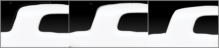
Figure 5-66: With the ClipCurve brush, clean up the edges of the car.

c05f066.tif
8. When you have a curve that you like, hold the spacebar and drag the entire car up so that it overlaps the edge of the surface slightly (see Figure 5-65, middle image). Release the brush to create the clip (see Figure 5-65, right image).

If you mess up, just press Ctrl+Z and try again. It usually takes a couple of tries. Even experienced users have to try a few times to get exactly the curve they want. The beauty of computer graphics is that you can undo the action, as opposed to sculpting in the real world where it is possible to permanently ruin your work!

9. Repeat these steps to refine the outside edges of the car’s profile, as shown in Figure 5-66. Remember that to make a sharp angle, tap the Alt key twice.
10. For the wheel well, you can try using the ClipCurve brush or switch to the ClipCircleCenter brush. Position the circular selection but hold the Alt key before releasing to create the circular clip (see Figure 5-67).

Figure 5-67: Use the ClipCurve brush to refine the wheel well.

c05f067.tif
11. You can use the same approach to refine the edges of the car from the top (see Figure 5-68). Press the X hotkey to activate Symmetry, and make sure the LSym button on the right shelf is on.

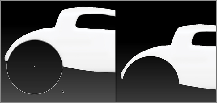
Figure 5-68: With the ClipCurve brush, clean up the edges of the car.

c05f068.tif
12. Click the Save As button in the File menu to save the project as HotRod_v06.ZPR.

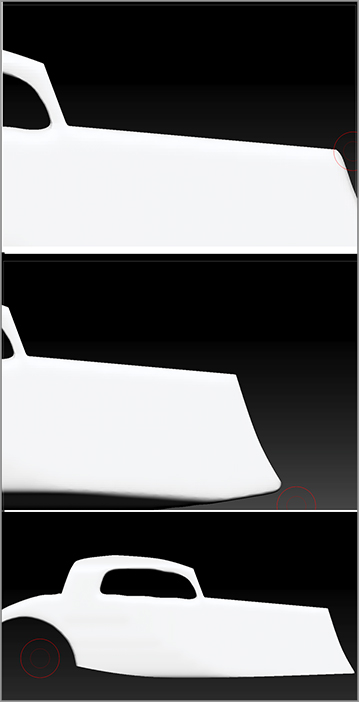
Clipping at an Angle

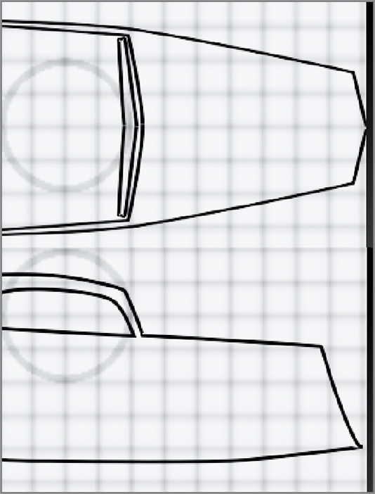
For some parts of the car, you’ll need to rotate your model to an odd angle in order to make a clean, straight cut. For example, in the reference drawings used in ShadowBox, the front of the car is pointed out like a wedge. In the side view, the front slopes down at an angle (see Figure 5-69).

Figure 5-69: From the top view (top image), the front of the car is angled to form a wedge. From the side view (bottom image), the front slopes at an angle.

c05f069.tif

If you use the ClipCurve brush to cut the wedge from a straight-on, top view, you’ll lose the sloping angle seen from the side. So in this case, to replicate that shape in 3D, you can simply rotate the view of the car to match the sloping angle of the front. It takes a little practice, but after a few tries you’ll get the hang of it. Follow these steps:

1. Open your saved version of HotRod_v06.ZPR.
2. Rotate the view of the car while holding the Shift key, and snap the view so that you’re looking at the car from the top (top image in Figure 5-70).
3. Carefully right-click drag on the canvas from right to left so that the front of the car rotates away from the camera. You want the slope of the front of the car to be perpendicular to the viewing angle (see Figure 5-70, bottom image).
4. Open the sculpting brush fly-out library and press C and then C again to choose the ClipCurve brush.
5. Make sure Symmetry is active across the x-axis, and click the LSym button on the right shelf to turn on Local Symmetry.

Figure 5-70: Rotate the view of the car so that you can see it from the top. Carefully rotate the view so that you’re looking down along the slope of the car’s front.

c05f070.tif
6. Hold Ctrl+Shift, and start dragging a curve down at an angle from left to right, as shown in Figure 5-71.
7. Release the brush, and then rotate the view and inspect the shape. If you didn’t quite get it, press Ctrl+Z to undo and try again.

Once you get the hang of this, you can try creating a rounded curve for the edge of the trunk. This is a bit trickier because it requires making a curve line that clips the edge of the hood and goes from the front of the car up to the front plane of the windshield. Before you make the clip, you’ll need to mask out the part of the car behind the windshield so it is not clipped as well.

Figure 5-71: Use the ClipCurve brush to clip the front of the car at an angle.

c05f071.tif
8. Rotate the car so that you can see it straight on from the side.
9. In the brush fly-out library, press M and then R to set the mask brush to MaskRect.
10. Hold the Ctrl key and drag a rectangular mask that covers the car from the windshield to the rear (see Figure 5-72).

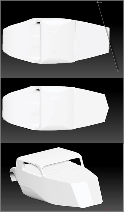
Figure 5-72: From the side view the car is masked from the windshield to the trunk.

c05f072.tif
11. Rotate the view so that you’re looking at the car along the edge of the hood.
12. Hold Ctrl+Shift and draw a short curving line, as shown in Figure 5-73. In this example, I clicked the Alt key twice while drawing the curve to create the two points necessary to make a smooth curve.
13. Release the brush to make the clip.
14. Rotate the view and inspect the clip. Undo and try again if it wasn’t quite right. This area will be cleaned up even further with the sculpting brushes, so it’s okay if the clip leaves some small bumps on the trunk (see Figure 5-73, lower-left image).

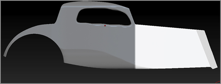
Figure 5-73: The view of the car is rotated so that the car is viewed down the edge of the hood. A clip curve is used to create the rounded edge.

c05f073.tif
15. Use these techniques to add a rounded edge to the roof and the trunk. Remember to use masks to control which parts of the car are clipped.
16. Click the Save As button in the File menu and save the project as HotRod_v07.ZPR.

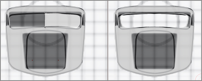
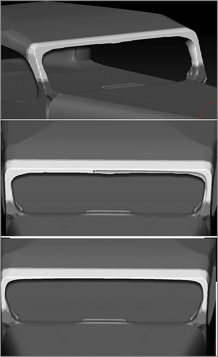
Refining the Windows Using Clip Brushes

The lasts parts of the car body that need some cleaning up are the window openings. This is a little tricky since you can’t create a closed loop with the clip curve. Again, using masks will help a lot (see Figure 5-74):

Figure 5-74: The window edges are refined using masking and the clip brushes.

c05f074.tif
1. Open your saved version of the HotRod_v07.ZPR project.
2. Rotate the view of the car while holding the Shift key, and snap the view so that you’re looking at the car from the side.
3. Use the MaskRect brush to mask everything below the top of the car.
4. Scale up the view so that you can see the window area up close.
5. Starting from the lower-right edge of the window, carefully draw out a curving line to match the shape of the upper part of the window opening.
6. Release the brush to make the clip.
7. Press Ctrl+I to invert the mask (or Ctrl+click on a blank part of the document). Draw the curve starting from the lower left and move toward the right to clip the bottom part of the window.

Figure 5-75: Use the ClipCurve brush to refine the opening for the windshield.

c05f075.tif
8. Use the same technique to clean up the edges of the opening for the front windshield. This time mask the bottom of the car as well as the back part of the car top so that the work you do on the front of the windshield does not affect the opening for the back window.
9. Enable Symmetry so you only have to draw a curve for one side of the windshield. Start from the lower right and draw a curve moving up and to the left around the top edge of the windshield. To eliminate kinks in the curve, press the Alt key to add points, even along the straight parts of the curve at the top (see Figure 5-75).
10. Save the project as HotRod_v08.ZPR.

Dynamesh and ClayPolish

At this point the edges should appear more refined, but no doubt the geometry is starting to look mangled. To fix this you can use Dynamesh, which will replace the topology with a unified skin while retaining the shape of the surface. Dynamesh was first introduced in Chapter 3. Follow these steps to “dynamesh” the surface:

1. Open your saved version of the HotRod_v08.ZPR project.
2. Open the Tool palette, and expand the Geometry subpalette. Under the Dynamesh button set the Resolution to 304. Based on the scale of this particular model I found that this resolution setting does a good job of retaining the overall contour of the body.
3. Click the Dynamesh button. After a couple seconds the body of the car will be retopologized. You can see the results of the new topology by turning on the PolyF button on the right shelf (Figure 5-76).

Figure 5-76: After you apply Dynamesh, the surface is retopologized.

c05f076.tif
4. Use the clip brushes to clean up any stray polygons, and click the Dynamesh button to retopologize again if needed. This removes any squished polygons created by using the clip brushes.
5. The edges may become “soft” or overly round after “dynameshing.” To sharpen the edges click the ClayPolish button in the Geometry subpalette of the Tool palette (see Figure 5-77).

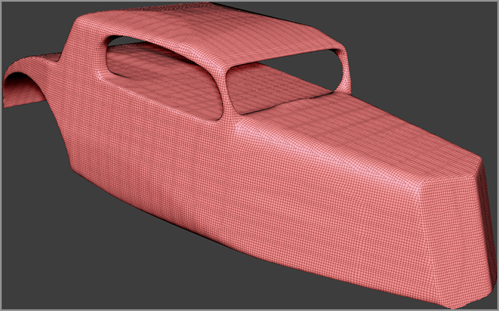
Figure 5-77: Click the ClayPolish button to sharpen the edges of the surface.

c05f077.tif
6. The ClayPolish button refines the corner of the mesh automatically. It also adds a mask that is not visible by default. After applying ClayPolish, hold Ctrl and drag on the canvas to remove the mask.
7. Save the project as HotRod_v09.ZPR.

You can turn the Polish option on in the Dynamesh settings. This automatically polishes the surface each time you apply Dynamesh.

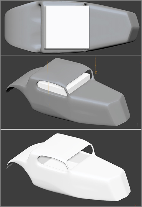
Creating a Space for the Interior of the Car

The car model will look a little more convincing with space inside for the driver and passengers. To accomplish this, you can use Dynamesh and the InsertCube brush:

1. Open HotRod_v09.ZPR.
2. Make sure the LSym button is activated on the right shelf so that the symmetry is aligned with the center of the car. Leave Symmetry on so that it’s easier to find the center of the car.
3. Select the InsertCube brush from the brush library.
4. Rotate the view so that you can see the car from the top.
5. Hold the Alt key and drag the cube. Make it large enough to cover the passenger area, and don’t worry if it intersects with the roof. Use Symmetry on the stroke so that you can insert the cube at the center of the car (see the top image in Figure 5-78).
6. Let go of the brush. A mask will be applied to the car, but the inserted cube is unmasked.
7. Switch to the Transpose brush in Move mode (hotkey = W). Use Transpose to move and scale the cube so it fits under the roof but does not penetrate the bottom of the car (see Figure 5-78, middle image).
8. Once the cube is positioned, hold Ctrl and drag on a blank part of the canvas to clear the mask. Then Ctrl+drag on the canvas to dynamesh the surface (see Figure 5-78, bottom image).

Because you held the Alt key when you inserted the cube instead of combining the cube and the car, the cube is used to cut a hole in the surface when Dynamesh is activated.

9. Save the project as HotRod_v10.ZPR.

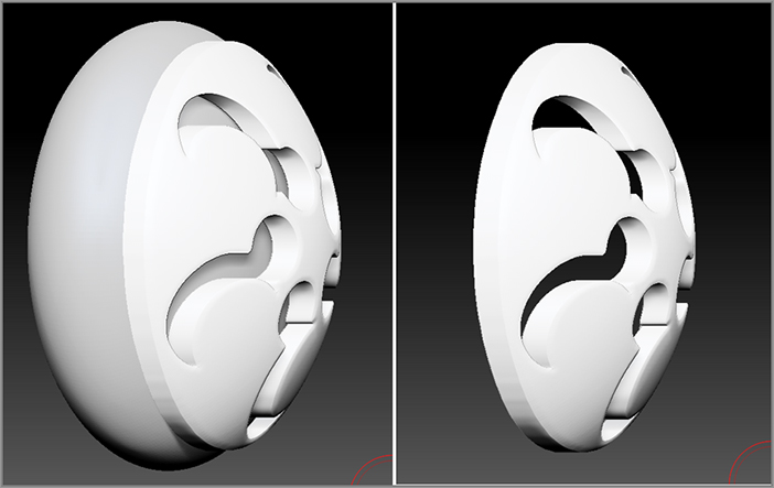
You now have the basic shape of the hot rod body, which is ready for sculpting and detailing.

Figure 5-78: Hold the Alt key while drawing a cube using the InsertCube brush. When the surface is “dynameshed” a square space is cut into the surface.

c05f078.tif
Using Dynamesh to Create Boolean Operations on Surfaces
Boolean operations refer to common ways of using one surface to shape a second surface. Users of other 3D modeling programs frequently create surfaces through subtraction or intersection, for example, using a primitive cylinder to cut a round hole through a thick piece of geometry. Most 3D modelers complain that in many applications Boolean operations create a lot of topological problems and errors with the resulting surface. In ZBrush, Dynamesh creates very clean geometry, so by using the insert brushes (InsertCube, InsertSphere, and the like) in subtract mode (that is, while holding that key) you can create some very creative designs through Boolean operations that would create extremely messy topologies in other 3D modeling software.

Summary

In this chapter you learned how to use the ShadowBox tool to generate a mesh for a car body. You learned how to create a reference image and apply it to the ShadowBox texture. You learned how to use the masking brushes to create a shape and then the clip brushes to refine the edges. The ClayPolish button was introduced as a way to sharpen the edges. You learned that you could click the Insert Mesh button while holding the Alt key to cut away into the surface of the hot rod to create a passenger area. You also learned how to use Radial Symmetry to create intricate designs with ShadowBox as well as how to use the MatchMaker brush to create the rounded shape of the hubcap.

..................Content has been hidden....................

You can't read the all page of ebook, please click here login for view all page.
Reset
18.118.205.165