Bonus Content 2
ZScripts and ZPlugins
ZScripts and ZPlugins are tools designed to extend the capabilities of ZBrush and make certain tasks much easier. ZScript is a simple scripting language that is essentially a list of commands. Many ZPlugins have been created using ZScript.
Pixologic offers a number of free ZPlugins, which can be downloaded from www.pixologic.com. The plug-ins are easy to install and use. Some of these plug-ins you’ve already encountered in previous chapters of this book.
This chapter demonstrates how to record, save, and use a simple ZScript. You’ll also learn how to install and use the ZPlugins available from Pixologic. This chapter includes the following topics:
- Using Quick Sketch ZScript
- Recording a ZScript
- Using Projection Master
- Installing a ZPlugin
- Using ZPlugins
Using ZScript
ZScript is a simple scripting language designed to automate basic tasks in ZBrush. A good example of a ZScript is Quick Sketch, which is activated when you click the Quick Sketch button on the top shelf.
You don’t actually need to write out a ZScript; ZBrush will create a ZScript for you by simply recording the actions you take within the ZBrush interface.
In this section, you’ll learn how to use Quick Sketch and also how to record and use your own ZScript.
Using Quick Sketch
The purpose of this ZScript is to transform the ZBrush canvas into an environment in which you can sketch out ideas by using the Pen Shadow brush (see Figure B2-1). If you click the button, you’ll see that the screen turns a light gray color. When you drag on the canvas, you’ll see stylized lines appear. Symmetry is activated, so the lines you draw on one side of the canvas are mirrored to the other side.
Figure B2-1: The Quick Sketch button rearranges the interface to make it easy to create symmetrical sketches on the canvas.
When you click the Quick Sketch button, ZBrush performs several tasks in order to make sketching possible. These tasks include the following:
- Creating a polygon plane that is parallel to the canvas
- Switching to Edit mode to ensure that the polygon plane can be edited
- Activating Symmetry across the x-axis
- Setting the current material to Flat Color
- Setting the current sculpting brush to Pen Shadow
These are all tasks you could easily perform yourself, but by recording the tasks as a ZScript, ZBrush makes setting up a Quick Sketch fast and easy.
After these tasks are performed, the ZScript stops, and you’re ready to start creating your own Quick Sketch on the canvas. The sketch itself is really just a sculpt created on a polygon plane. You can scale and rotate the view of the plane, just as you can with any other tool. If you want to save your sketch as an image, use the Export button in the Document palette.
Recording a ZScript
ZScripts are easy to create. You don’t need to learn the ZScript language; you can simply record the actions you perform on the screen, and ZBrush will create the ZScript for you.
The important thing to understand about recording a ZScript is that the ZScript is very literal. It records exactly what you do while in ZBrush. If you record a ZScript while working on a customized 3D tool, the ZScript will expect to use that same tool whenever you run the ZScript. If ZBrush can’t find the tool, the ZScript will automatically abort. For this reason, it’s best to make your ZScripts as generic as possible.
In this example, you’ll record a ZScript that loads a PolySphere onto the canvas in Edit mode and then subdivides the PolySphere:
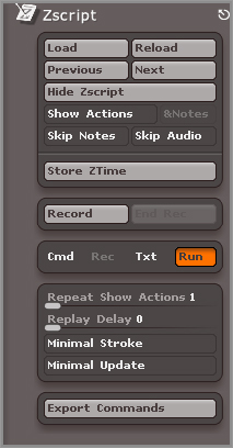
Figure B2-2: The ZScript palette contains controls for loading and recording ZScripts.
When you save the ZScript, three files are saved to your ZScripts folder: a text file named makePSphere.TXT, which is a plain-text file with all of the ZBrush commands recorded in order (see Figure B2-3); a file named makePSphere.ZSC, which is the actual ZScript file; and a file named makePSphere.PSD, which is a screen grab of the canvas that can be used as a ZScript icon.
The long string of letters and numbers that you see in the ZScript text file is a record of coordinates that track the movements you made on the canvas while recording the ZScript.
Figure B2-3: The ZScript is a text file that is a list of the recorded commands.
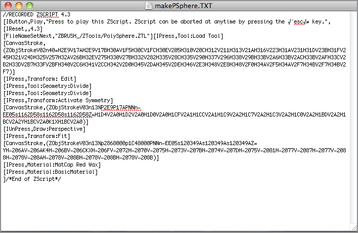
The long string of letters and numbers that you see in the ZScript text file is a record of coordinates that track the movements you made on the canvas while recording the ZScript.
Loading and Running Your ZScript
There are a couple of ways to load the ZScript. You can use the Load button in the ZScript palette or double-click the icon in the Scripts section of LightBox. Follow these steps to load a ZScript:
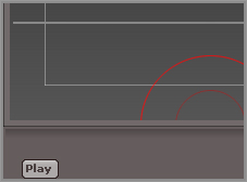
Figure B2-4: Click the button labeled Play in the bottom tray below the canvas.
In some cases, you can skip initialization depending on what the script does. In this case, if you skip initialization, the results will be kind of strange.
Figure B2-5: A warning appears asking whether you want to initialize ZBrush.
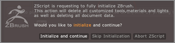
When you click the Initialize And Continue button, the script will execute, and you’ll see ZBrush execute the recorded commands. At the end of the script, you’ll have a PolySphere on the canvas ready for sculpting.
If you want to see the text of the ZScript in the ZScript window in the bottom tray, click the Txt button in the ZScript palette. The Cmd button displays a list and description of ZScript commands. This can be helpful if you want to write or edit your own ZScripts.
Using Projection Master
Projection Master is a plug-in that comes preloaded in ZBrush. It is activated by clicking the Projection Master button on the top shelf. The purpose of the plug-in is to let you paint and detail your models by using the 2.5D brushes. Prior to ZBrush 3, Projection Master was used to edit digital sculpts. Since ZBrush version 3 introduced the sculpting brushes, the usefulness of this plug-in has diminished; however, many users still prefer to work in Projection Master. In this section, you’ll get a brief overview of how the plug-in works.
Sculpting a Surface in Projection Master
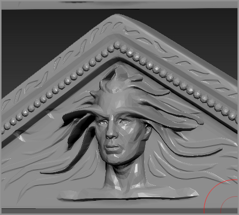
Projection Master can be used to sculpt details into a surface using the 2.5 dimensional brushes normally used for creating illustrations. Some artists like to use Projection Master when sculpting architectural details. This tutorial demonstrates how Projection Master can be used to create a bas relief for the side of an ancient temple.
Figure B2-6: Rotate the model so that it is facing the front.
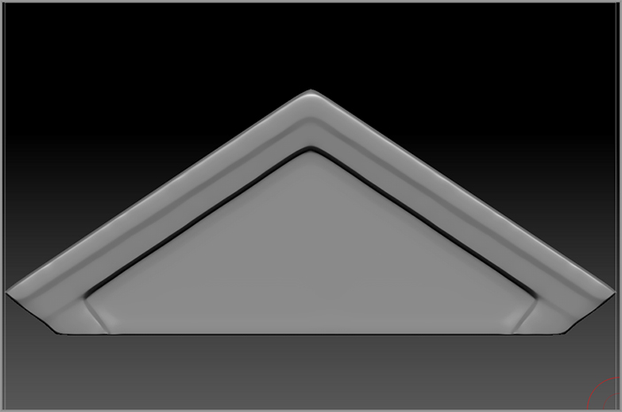
Figure B2-7: Set the options in the Projection Master window and click Drop Now.
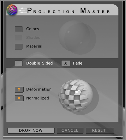
When you click Drop Now, the model is temporarily dropped to the canvas. This means you can no longer rotate the model or use symmetry. The model has been converted to pixols. This means that you now can use the 2.5 dimensional brushes to sculpt the model. It also means a number of stroke types are now available that are not normally available for the regular sculpting brushes.
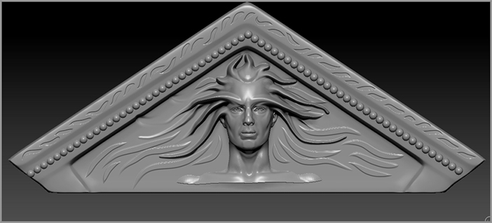
Figure B2-8: Choose the DecoBrush from the tool library.
Figure B2-9: Draw a series of leaflike designs along the top edge of the roof.
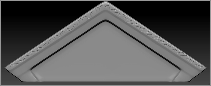
Figure B2-10: Select the LineII stroke type and set the Spacing slider to 1.
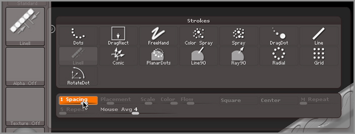
Figure B2-11: Draw a line of spheres along the top edge of the temple roof.
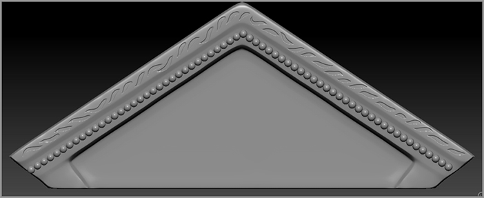
Figure B2-12: Draw the DemoHead onto the front of the surface. Use the Smudge brush and DecoBrush to add radiating lines coming from the head.
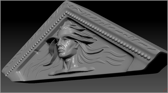
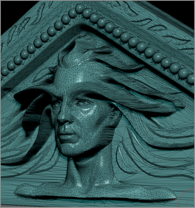
After a few moments the model is returned to Edit mode, and you can once again rotate it and use the sculpting brushes to shape it. The changes you created while in Projection Master are used to displace the geometry (see Figure B2-13). If the model is low resolution, the resulting model will not look as detailed as it did while Projection Master was active. You may need to use the sculpting brushes to clean up stretched parts on the surface.
Projection Master can be used to paint colors and materials onto a surface. This is useful if you like to use the 2.5 dimensional brushes, but in most cases I think it’s easier to use the polypainting techniques described in Chapter 8. If you do use Projection Master to paint a surface, you will need to create UV texture coordinates and create a blank texture using the New Txtr button in the Texture Map subpalette of the Tool palette.
Figure B2-13: When you leave Projection Master the model is returned to Edit Mode and can be rotated and sculpted once again. The changes made in Projection Master are used to displace the geometry of the surface.
Using ZPlugins
ZPlugins extend the capabilities of ZBrush, making many tasks much easier. ZPlugins are available for free as a download from www.pixologic.com. Periodically, Pixologic adds new ZPlugins to their website. In addition, the ZClassroom on the website has video tutorials on the use of many of these plug-ins.
In this section, you’ll learn how to install the plug-ins and how to use the ZPlugins that are currently available for ZBrush 4.
Installing a ZPlugin
Installing a ZPlugin is easy. In this example, you’ll see how to install UV Master as an example. The other ZPlugins use the same method. Follow these steps:
Figure B2-14: Download ZPlugins from the Download Center on the Pixologic website.
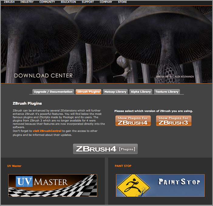
Figure B2-15: Click the link to download the version appropriate for your operating system.
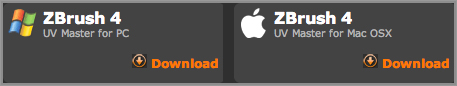
Figure B2-16: Move the files to the ZPlugs directory in the ZBrush 4 R3 folder.
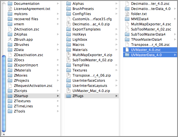
If you don’t see the ZPlugin installed, make sure that you have moved the ZScript file and the folder to the ZPlugs directory. It’s tempting to put the unzipped UVMaster folder in the ZPlugs folder, but if you do this, ZBrush will not be able to locate the necessary files and the ZPlugin will not load.
Some ZPlugins, such as ZAppLink, will not appear in the ZPlugin palette when they are installed. ZAppLink appears in the Document palette. If you can’t find the ZPlugin, download the appropriate documentation and double-check to see where it is supposed to appear in the interface. The descriptions of the ZPlugins within this chapter will let you know how to find and use them as well. For future ZPlugins released after this book is published, always check the documentation.
If a ZPlugin is not installed correctly, ZBrush could fail to launch. Try holding the Shift key while ZBrush is loading; this skips all ZPlugins, and at the very least ZBrush should open.
UV Master
UV Master is a must-have ZPlugin. Mapping UV texture coordinates is necessary when converting polypainted colors to file textures for use in other programs or when creating normal and displacement maps. Working with UV coordinates is explained in Chapter 8, “Polypainting and SpotLight,” and in Bonus Content 1, “GoZ.” Generally speaking, UV mapping is about as much fun as doing your taxes. Anything that makes it easier and faster is a welcome tool, and that’s exactly what UV Master is meant to do.
UV Master gives you a quick and easy way to generate a UV layout that still resembles the shape of the original surface. It is not meant to be quite as powerful as software such as UVLayout by headus, which is devoted to making advanced UV texturing coordinates. Rather, UV Master should be used when you want to create a UV layout as quickly as possible with a minimum amount of labor. You can use the UV coordinates generated by UV layout as a starting point for further editing in other software. That being said, the UV coordinates created by UV Master are usually very good and certainly usable for most common texturing situations.
The following exercise is a brief overview of the basic controls for using UV Master. The ZPlugin itself is fairly powerful. For more detailed information, consult the UV Master documentation, which can be downloaded from the Pixologic website at www.pixologic.com/zbrush/downloadcenter/zplugins. Follow these steps:
Figure B2-17: Orange lines appear on the surface of the model, indicating the position of UV seams.
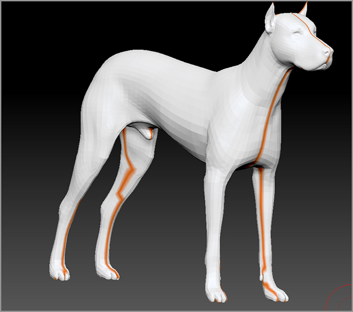
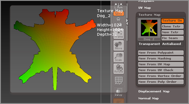
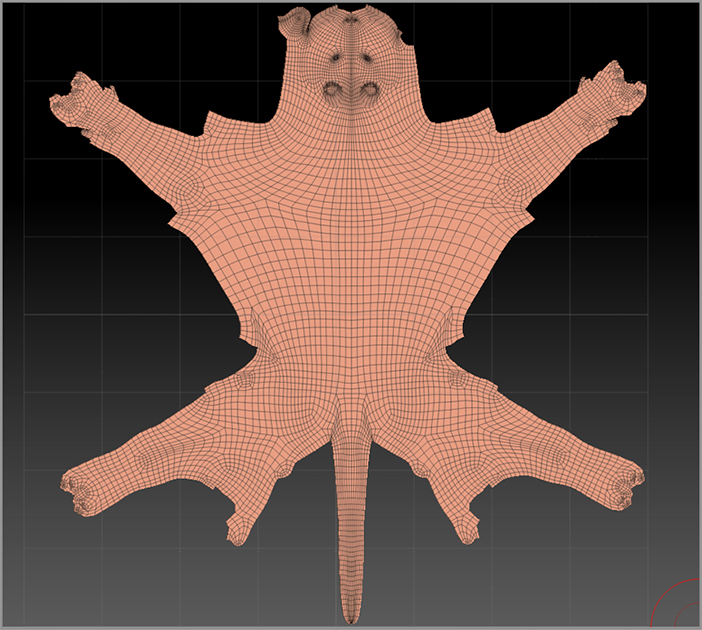
Figure B2-18: The flattened view shows how the UVs are arranged for the model.
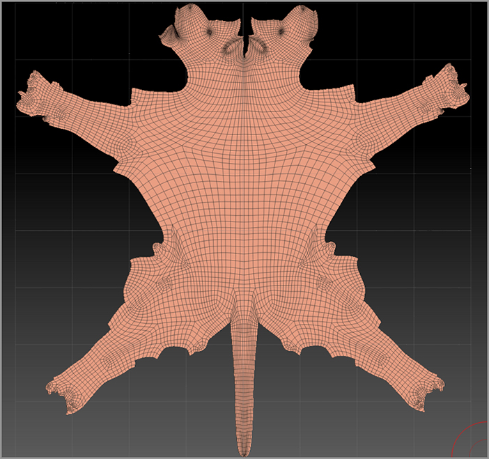
Figure B2-19: The pasted UV coordinates look just like the flattened version of the cloned dog.
There are some other options within the UV Master ZPlugin interface:
Control Painting UVs
UV Master unwraps the model to create UVs as efficiently as possible while still maintaining the overall shape of the surface. However, UV Master has no way of knowing which part of your model is a head and which is a hand. Unlike other UV editing programs such as UVLayout by headus, you don’t have direct control over where UV Master places the UV seams, but you can give UV Master a clue as to which parts of the model are better suited for seams and which parts should be protected. To do this, you can use the Control Painting options:
Figure B2-20: The orange line indicates that there is a UV seam running down the center of the dog’s head.
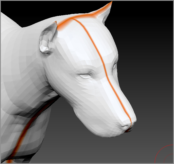
Figure B2-21: Turn on the Protect button in the UV Master interface.
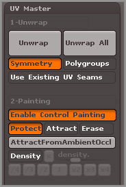
Figure B2-22: Paint the top of the dog’s head red.
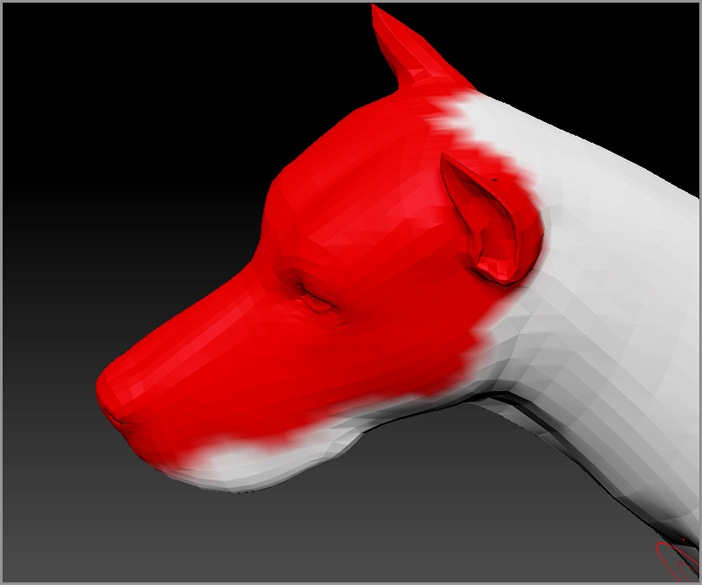
Figure B2-23: No orange lines appear on the top of the dog’s head, indicating that there are no UV seams there.
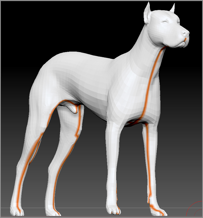
Figure B2-24: The flattened dog after the UV coordinates have been recalculated.
The other options in the Enable Control Painting section perform the following functions:
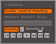
Figure B2-25: The Density feature lets you paint areas on the surface where you want more or less texture space.
PaintStop
PaintStop emulates a digital painting program such as Adobe Photoshop or Corel Painter within ZBrush. When you launch PaintStop, the ZBrush interface is transformed into a painting environment. However, any tools that you have on the canvas are still visible. You can use the painting tools within PaintStop to trace your model. This makes digital illustration within ZBrush even easier.
When you have finished, you can export the images directly from the PaintStop interface or, as with Projection Master, project your painting onto the surface of any tools on the canvas.
This exercise demonstrates how to use PaintStop. For complete instructions on all the buttons in the PaintStop interface, download the documentation from www.pixologic.com/zbrush/downloadcenter/zplugins.
Figure B2-26: A dragon model with the FlatSketch01 material applied
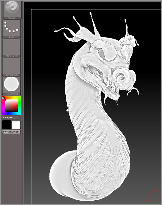
Figure B2-27: The PaintStop ZPlugin button is found in the Document palette.
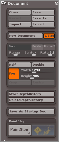
Figure B2-28: Warning messages may appear when you launch PaintStop.
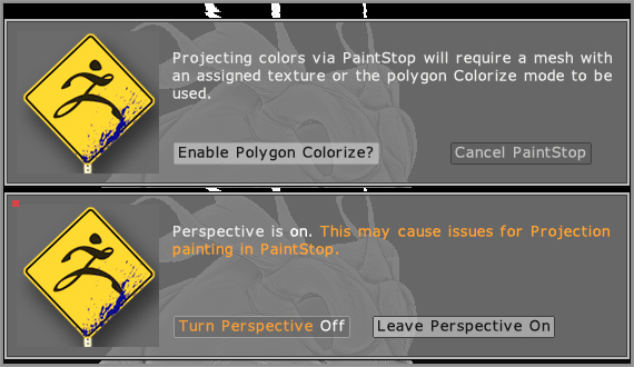
Figure B2-29: The PaintStop plug-in replaces the ZBrush interface with a new interface designed to emulate a painting program. Use the Transparency slider to adjust the opacity of the canvas so you can trace your dragon model.
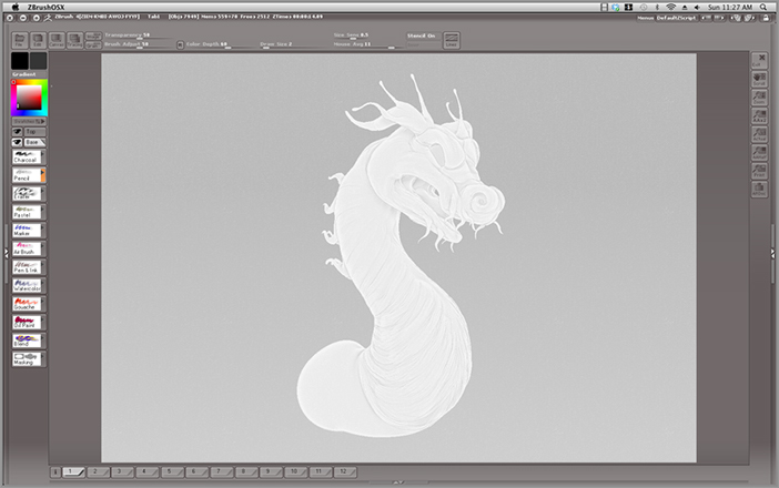
Figure B2-30: Click the Coarse Linen Canvas button to choose a grain pattern for the canvas.
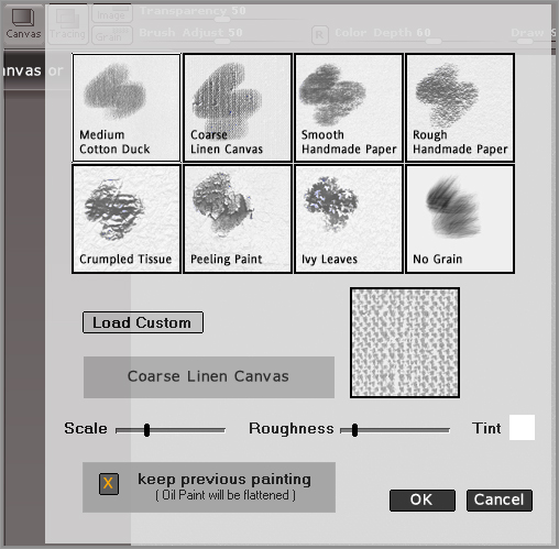
Figure B2-31: Use the brushes to trace the image of the model. Set Transparency to 0 to see the image without the model.
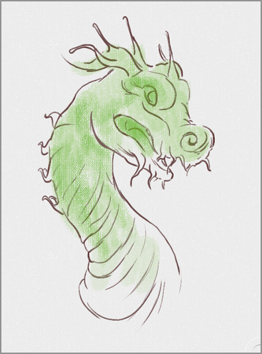
Figure B2-32: When you Exit PaintStop, a dialog asks whether you want to project the painting onto the model.
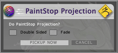
The Projection feature works just like Projection Master, described earlier in this chapter: Anything you paint on the canvas will be projected onto the model, so PaintStop acts as another way to texture your surfaces.
The tabs at the bottom of PaintStop store the images you create. Each time you launch PaintStop during a ZBrush session, these tabs will store the work you have done so you can continue to work on a number of paintings within a session.
3D Print Exporter
3D Print Exporter is a simple plug-in that exports your model in various formats that can be read by 3D printing software. You install the ZPlugin by using the same method described earlier in the “Installing a ZPlugin” section.
You have the option of exporting the selected subtool or all subtools (see Figure B2-33). You can set the size of the print and then choose the format. Some formats will also accept the color information painted on the surface.
Figure B2-33: The interface for 3D Print Exporter
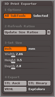
If you plan to export your models for 3D printing, make sure you understand which options your 3D printing software requires. Figure B2-33 shows the interface for the 3D Print Exporter plug-in.
Decimation Master
Decimation Master is used to convert a highly detailed, high-resolution mesh (meaning a mesh with millions of polygons) into a lower-resolution version while maintaining as much of the original detail as possible. 3D printing software often can’t accept models above a certain polygon count or files above a certain size. Decimating a model is a way to prepare the surface so it can be exported from ZBrush (by using the 3D Print Exporter ZPlugin) and printed out as a three-dimensional surface.
Many CG artists who use 3D animation software such as Autodesk® Maya® and 3ds Max® or Luxology’s modo use Decimation Master as an alternative to displacement maps and normal maps for rendering the highly detailed surfaces produced in ZBrush. In some cases, a decimated version of the model will look better than a version that uses displacement maps in a render using other 3D software. However, the decimated version of the model will have a topology that is not suitable for animation, so many artists decimate only models that are static, such as statues or scenery.
The documentation for Decimation Master is available at www.pixologic.com/zbrush/downloadcenter/zplugins. This exercise demonstrates the basics of using the ZPlugin.
First, you’ll prepare a surface for decimation:
Figure B2-34: Drop a copy of the model to the canvas for use as a visual reference. Move the model down toward the lower half.
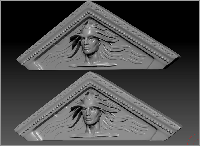
Figure B2-35: When the model is decimated at 0.1% of the original 4 million polygons, the result is somewhat blocky and detail is lost.
For models in which the level of detail is different on various parts of the surface, you’re more likely to get smaller polygons only where needed to preserve the detail, and you’ll have a more efficient decimation allowing for lower k Polys settings. You can mask areas of the model before you decimate to more precisely control which parts of the model have more or fewer polygons and thus keep high-resolution detail exactly where you want it.
Figure B2-36: The model is decimated at 1%. The wireframe is visible, allowing you to see how the polygons have been decimated.
ZAppLink 3
ZAppLink combines the power of polypainting surfaces in ZBrush with the paint tools of your favorite digital painting software, such as Adobe Photoshop or Corel Painter. The ZPlugin works similar to Projection Master in that, when activated, the current 3D tool is dropped to the canvas. However, instead of opening a ZBrush plug-in such as Projection Master, ZAppLink opens your digital paint program, letting you use your favorite brushes and painting techniques to paint on a still image of the model.
When you’ve finished painting in the other application, you can go back into ZBrush and pick up the model off the canvas. All the paint strokes created in your digital paint program are projected onto the surface. You can then rotate the view of the model, use ZAppLink to go back into your paint program, and then continue painting.
This exercise demonstrates the process:
Figure B2-37: The ZAppLink button is in the Document palette.
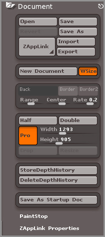
Figure B2-38: Click the Set Target App button to set the target paint program.
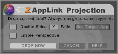
Figure B2-39: The layer arrangement in Adobe Photoshop. Do all of your painting on Layer 1.
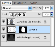
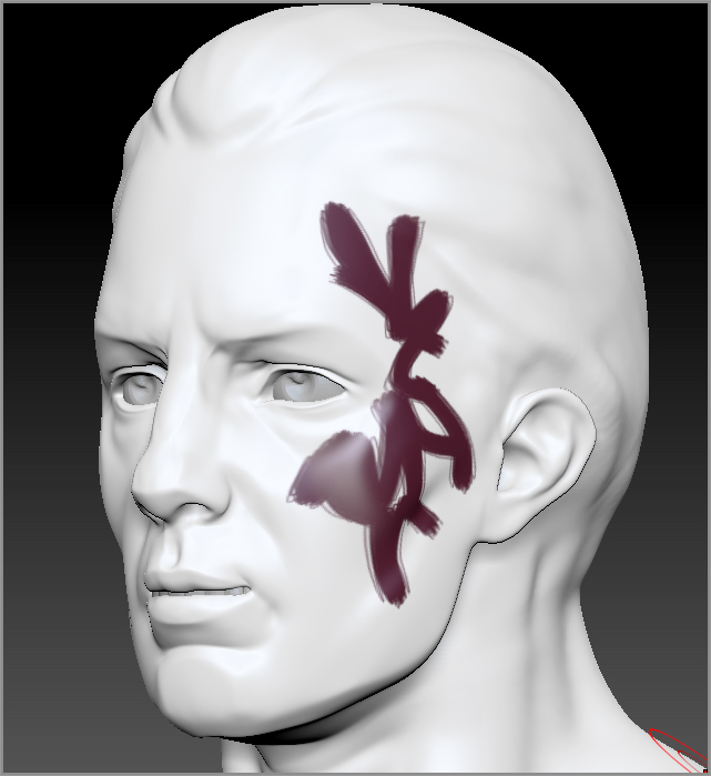
Figure B2-40: Colored strokes are painted on the head in Photoshop.
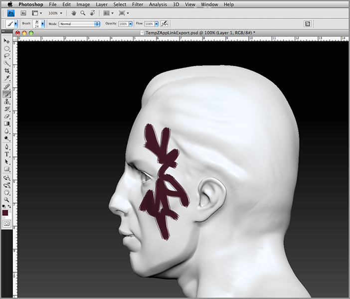
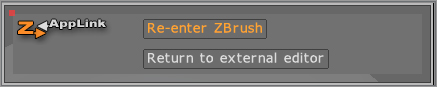
Figure B2-41: Click the Re-Enter ZBrush button.
After a few seconds, the colors you painted in Photoshop are projected onto the surface (see Figure B2-42). Because Double Sided has been selected, the colored strokes are projected through the surface, creating a symmetrical pattern.
ZAppLink is a powerful ZPlugin that enables you to take advantage of any techniques or custom brushes you’ve created in your favorite digital paint program.
Figure B2-42: The strokes painted in Photoshop are projected onto the surface in ZBrush.