
Chapter 4
Input Output Media
This chapter deals with two basic computer units—input and output devices. Input devices are used to enter the data and instructions into the computer system before any processing can be performed. Output devices are used for the conversion of machine-readable information into human-readable form. The chapter discusses some commonly used input devices including keyboard, mouse, joystick, scanner, and optical scanners. The functions of all these input devices along with the hard copy and soft copy output devices under which, various types of printers and plotters have been explored. Next display devices such as CRT monitors, LCD monitors and speech synthesisers are explained. The chapter concludes by giving an overview of computer terminals.
After reading this chapter, you will be able to understand:
The basic concepts of input and output devices
Various types of input devices and how they function
Various types of output devices and how they function
Computer terminals which are special units capable of performing both input and output of data
4.1 INTRODUCTION
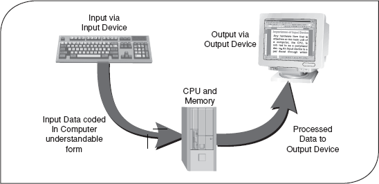
Previously, we discussed that a computer accepts input and processes it to get a desired output according to the sequence of instructions. Essentially, a computer system consists of four components: input devices, CPU, output devices and memory. Input devices are used to provide data to the CPU for processing. After processing, the input data is converted into meaningful information and this output is presented to the user with the help of output devices. In computer terminology, a device can be referred to as a unit of hardware, which is capable of providing input to the computer or receiving output, or both.
An input device is an electromechanical device that allows the user to feed information into the computer for analysis, storage and to give commands to the computer. Data and instructions are entered into the computer's memory through an input device. It captures information and translates it into a form that can be processed and used by the other parts of the computer. After processing the input data, the computer provides the results with the help of output devices. An output device converts machine-readable information into human-readable form. The basic functioning of the output device is just the opposite of the input device, that is, the data is “fed into” the computer system through the input device while the output is “taken out” from the computer through the output device. However, the output, which comes out from the CPU, is in the form of digital signals (see Figure 4.1). The output devices display the processed information by converting them into graphical, alphanumeric, or audio-visual form.
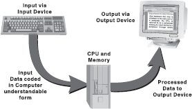
Figure 4.1 Data Processing
4.1.1 Importance of Input/Output Devices
As we know, the processing of the data by the computer system can be viewed as a three-step process:
| Step 1 | Data input via an input device. |
| Step 2 | Processing of data. |
| Step 3 | Data output via an output device. |
Input devices play a major role in the processing of any data via the computer system because the output of the computer is always based on the given input. Generally, data that is given to the input devices is raw. Therefore, it is the function of the input devices to manipulate the raw data and then send them for further processing. The preparation of the computerized input is the initial step in the creation of useful output. This output must be supplied to the outside world, which is done through output devices.
4.2 TYPES OF INPUT DEVICES
Computer accepts input in two ways, either manually or directly. In case of manual data entry, the user enters the data into computer by hand, for example, by using keyboard and mouse. A user can also enter data directly by transferring information automatically from a source document (like from a cheque using MICR) into the computer. The user does not need to enter information manually. Direct data entry is accomplished by using special direct data entry devices like a barcode reader. Some of the commonly used input devices are keyboard, pointing devices like mouse and joystick, speech recognition, digital camera and scanners.
4.2.1 Keyboard
FACT FILE
Qwerty Query
The layout of a keyboard comes in various styles, such as QWERTY, AZERTY and DVORAK. QWERTY is the most common layout in English language computer keyboards. It takes its name from the first six letters shown on the keyboard's top row of letters. Similarly, French language keyboards use A and Z in place of Q and W and are known as AZERTY keyboards.
A keyboard is the most common data entry device. Using a keyboard, the user can type text and commands. The keyboard is designed to resemble a regular typewriter with a few additional keys (see Figure 4.2). Data is entered into the computer by simply pressing keys. The layout of the keyboard has changed very little since it was introduced. In fact, the most common change in its technology has simply been the natural evolution of adding more keys that provide additional functionality. The number of keys on a typical keyboard varies from 84 to 104.
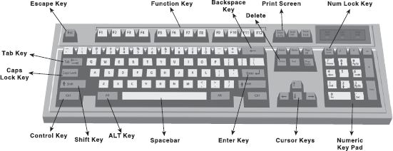
Figure 4.2 Keyboard
Portable computers such as laptops quite often have custom keyboards that have slightly different key arrangements than a standard keyboard. In addition, many system manufacturers add special buttons to the standard layout. A keyboard is the easiest input device, as it does not require any special skill. Usually, it is supplied with a computer so no additional cost is incurred. The maintenance and operational cost of a keyboard is also less. However, using a keyboard for data entry may be a slow process because the user has to manually type all the text. In addition, it can be difficult for people suffering from muscular disorders.
How does the keyboard work? A keyboard is a series of switches connected to a small keyboard microprocessor that monitors the state of each switch and initiates a specific response to a change in state. When the user presses a key, it causes a change in the amount of current flowing through the circuit associated specifically with that key. The keyboard microprocessor detects this change in current flow. By doing this, the processor can tell when a key has been pressed and when it is being released. Depending upon which key's Figure 4.3 Working of a Keyboard circuit carries a signal to the microprocessor, the processor generates the associative code, known as scan code, of the key and sends it to the operating system (see Figure 4.3). A copy of this code is also stored in the keyboard's memory. When the operating system reads the scan code, it informs the same to the keyboard and the scan code stored in keyboard's memory is then erased.
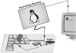
Figure 4.3 Working of a Keyboard
Initially, the processor filters all the tiny current fluctuations out of the signal and treats it as a single key press. If the user continues to hold down a key, the processor determines that the user wishes to send that character repeatedly to the computer. In this process, the delay between each instance of character can normally be set in the operating system, typically ranging from 2–30 characters/second (cps).
4.2.2 Pointing Devices
Most computers come with an alphanumeric keyboard but in some applications, the keyboard is not convenient. For example, if the user wants to select an item from a list, the user can identify that item's position by selecting it through the keyboard. However, this action could be performed quickly by pointing at the correct position. A pointing device is used to communicate with the computer by pointing to locations on the monitor screen. Such devices do not require keying of characters; instead the user can move a cursor on the screen and perform move, click, or drag operations. Some of the commonly used pointing devices are mouse, trackball, joystick, light pen, touch screen and trackpad.
Mouse: A Mouse is a small handheld pointing device with a rubber ball embedded at its lower side and buttons on the top. Usually, a mouse contains two or three buttons, which can be used to input commands or information (see Figure 4.4). It may be classified as a mechanical mouse or an optical mouse, based on the technology it uses. A mechanical mouse uses a rubber ball at the bottom surface, which rotates as the mouse is moved along a flat surface, to move the cursor. It is the most common and least expensive pointing device. An optical mouse uses a light beam instead of a rotating ball to detect movement across a specially patterned mouse pad. As the user rolls the mouse on a flat surface, the cursor on the screen also moves in the direction of the mouse's movement. It is pricier than their mechanical counterparts but are accurate and often do not need a mouse pad.
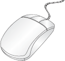
Figure 4.4 Mouse
FACT FILE
Wireless Keyboard and Mouse
With the increasing use of wireless technology, the wireless versions of keyboard and mouse have also been developed. Rather than connecting through wires, they connect with the computer using one of the three technologies, namely, Bluetooth, infrared, or radio frequency. The wireless keyboard requires three AA batteries and the wireless mouse requires two AA lithium batteries to operate. They also have a power switch on the bottom to turn them ON or OFF. The use of wireless devices helps in eliminating the wiring tangles around the PC and provides mobility and flexibility to the user to position him/her self relative to the computer.
A mouse allows us to create graphic elements on the screen such as lines, curves and freehand shapes. Since it is an intuitive device, it is easier and convenient to work as compared to the keyboard. Like a keyboard, it is also supplied with a computer; therefore, no additional cost is incurred. However, it needs a flat space close to the computer. The mouse cannot easily be used with laptop (notebook) or palmtop computers. These types of computers need a trackball or a touch sensitive pad called a touchpad.
How does a mouse work? As shown in Figure 4.5, a mechanical mouse has a rubber ball at the bottom. When the user moves the mouse along the flat surface, the ball rolls. The distance, direction and speed of the ball's motion is tracked. This information is used by the computer to position the mouse pointer on the screen. Inside the mouse are three rollers. One of them, which is mounted at a 45° angle to the other two, is spring loaded. This roller is usually the smallest of the three. It is there simply to hold the ball against the other two rollers. The other two rollers are usually larger, and of different colour. These rollers are mounted at a 90° angle to one another, one roller measures how fast the ball is turning horizontally, and the other measures how fast it is turning vertically. When the ball rolls, it turns these two rollers. The rollers are connected to axles, and the axles are connected to a small sensor that measures how fast the axle is turning. Both sets of information are passed to the electronics inside the mouse. This little processor, usually consisting of little more than a single chip, uses the information to determine how fast the mouse itself is moving, and in what direction. This information is passed to the computer via a mouse cord, where the operating system then moves the pointer accordingly.
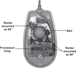
Figure 4.5 Inside a Mechanical Mouse
The optical mouse uses an infrared light and special mouse pads with fine grid lines to measure the rotation of the axle. The axle in optical mouse is connected to a little photo-interrupter wheel with a number of tiny holes in it. In front of this wheel is a light source and on the other side of the wheel is a light metre. As the wheel turns, the light flashes through the holes in the wheel. By measuring how often these flashes occur, the light sensor can measure how fast the wheel is turning and sends the corresponding coordinates to the computer. The computer moves the cursor on the screen based on the coordinates received from the mouse. This happens hundreds of times each second, making the cursor appear to move very smoothly.
Trackball: A Trackball is another pointing device that resembles a ball nestled in a square cradle and serves as an alternative to a mouse. In general, a trackball is as if a mouse is turned upside down (see Figure 4.6). It has a ball, which can be rotated by fingers in any direction, the cursor moves accordingly. The size of the ball in the trackball varies from as large as a cue ball, to as small as a marble. Since it is a static device, instead of rolling the mouse on the top of the table the ball on the top is moved by using fingers, thumbs and palms. This pointing device comes in various shapes and forms but with the same functions. The three shapes, which are commonly used are a ball, button and square.
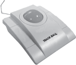
Figure 4.6 Trackball
Like the mouse, a trackball is also used to control cursor movements and the actions on a computer screen. The cursor is activated when buttons on the device are pressed. However, the trackball remains stationary on the surface, only the ball is moved with the fingers or palm of the hand. By moving just the fingers and not the entire arm, the user can get more precision and accuracy, which is why many graphic designers and gamers choose to use trackball instead of mouse. In addition, since the whole device is not moved for moving the graphic cursor, a trackball requires less space than a mouse for operation. A trackball, generally, tends to have more buttons. A lot of computer game enthusiasts and graphic designers also tend to choose to have more buttons to cut down on keyboard use. These extra buttons can also be re-programmed to suit whatever functions they require. Trackballs are not supplied normally so an additional cost is always charged. Moreover, before using them, a user has to learn how to use them.
How does a trackball work? A trackball works in the same way as a mouse, with the ball turning rollers, the rollers turning axles, which are in turn connected to either mechanical or optical sensors that measure their rotation. As shown in Figure 4.7, a trackball consists of a number of components. As one moves the trackball, it starts a chain of events inside the box that results in the pointer moving on the computer screen. In a normal trackball, on one side of each encoding wheel is a pair of LEDs (light emitting diode) that emits infrared light. On the opposite side of each pair of LEDs is a light sensor. Every time light from the LEDs shines through a hole in the encoding wheel, a pulse of electricity is sent from the light sensor to the microprocessor. When the trackball rolls side-to-side, the horizontal (x-axis) shaft rotates, spinning the attached encoder wheel. Similarly, when the trackball is rolled up and down, the vertical (y-axis) shaft rotates, spinning the attached encoder wheel. Due to this spinning, the light blinks, which can be detected by the light sensor. The microprocessor counts how many times the light sensors detect light each second and sends this information to the computer along the cord.
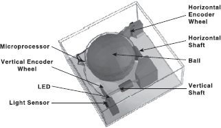
Figure 4.7 Inside a Trackball
Joystick: A joystick is a device that moves in all directions and controls the movement of the cursor. The basic design of a joystick consists of a stick that is attached to a plastic base with a flexible rubber sheath. This plastic base houses a circuit board that sits beneath the stick. The electronic circuitry measures the movement of the stick from its central position and sends the information for processing. A joystick also consists of buttons which can be programmed to indicate certain actions once a position on the screen has been selected using stick (see Figure 4.8). It offers three Figure 4.8 Joystick types of control: digital, glide and direct. Digital control allows movement in a limited number of directions such as up, down, left and right. Glide and direct control allow movements in all directions (360°). Direct control joysticks have the added ability to respond to the distance and speed with which the user moves the stick.
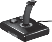
Figure 4.8 Joystick
A joystick is generally used to control the velocity of the screen cursor movement rather than its absolute position. It is used for computer games. The other applications in which it is used are flight simulators, training simulators, CAD/CAM systems and for controlling industrial robots.
How does a joystick work? Various joystick technologies are available and they differ mainly in how much information they pass on. All joysticks are designed to inform the computer about the positioning of the stick at any given time. This is done by providing the x – y coordinates of the stick. The x-axis represents the side-to-side position and the y-axis represents the forward block position (see Figure 4.9). The circuit board that sits directly underneath the stick carries electricity from one contact point to another. When the joystick is in neutral position, all but one of the individual circuits is broken. Each broken section is covered with a simple plastic button containing a tiny metal disc. When the stick is moved in any direction, it pushes down on one of these buttons, pressing the conductive metal disc against the circuit board. This closes the circuit, that is, it completes the connection between the two wire sections. When the circuit is closed, electricity can flow down a wire from the computer and to another wire leading back to the computer. When the computer picks up a charge on a particular wire, it knows that the joystick is in the right position to complete that particular circuit. The joystick buttons work exactly the same way. When a button is pressed, it completes a circuit and the computer recognizes a command.
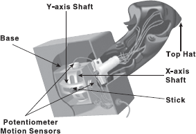
Figure 4.9 Inside a Joystick
Light Pen: A light pen (sometimes called mouse pen) is a hand-held electro-optical pointing device which a when touched to or aimed closely at a connected computer monitor, will allow the computer to determine where on that screen the pen is aimed. It facilitates drawing images and selects objects on the display screen by directly pointing to the objects. It is a pen-like device, which is connected to the machine by a cable (see Figure 4.10). Although named light pen, it actually does not emit light but its light-sensitive diode would sense the light coming from the screen. The light coming from the screen causes the photocell Figure 4.10 Light Pen to respond by generating a pulse. This electric response is transmitted to the processor that identifies the position to which the light pen is pointing. With the movement of light pen over the screen, the lines or images are drawn.
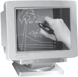
Figure 4.10 Light Pen
Light pens give the user the full range of mouse capabilities without the use of a pad or any horizontal surface. Using light pens, users can interact more easily with applications, in such modes as drag and drop, or highlighting. It is used directly on the monitor screen and it does not require any special hand–eye coordinating skills. Pushing the light pen tip against the screen activates a switch, which allows the user to make menu selections, draw and perform other input functions. Light pens are perfect for applications where desk space is limited, in harsh workplace environments, and any situation where fast accurate input is desired. It is very useful to identify a specific location on the screen. However, it does not provide any information when held over a blank part of the screen. A light pen is economically priced and requires little or no maintenance.
How does a light pen work? The light pen contains a lens and a photo detector located in its tip (see Figure 4.11). When the electron beam that sweeps the monitor strikes the phosphor within the light pen's field of view, the light emitted by the phosphor is focused through the lens and onto the photo detector. Due to this, the signal current is increased and is transmitted to the computer. The position of the beam is tracked by the horizontal and vertical counters, which relay this information to a register. This cycle is repeated for every frame produced by the electron beam. By noting when a scan goes by and measuring the interval between scan lines or entire screen refreshes, an accurate position of the photo detector on the screen is determined. The light pen software generates x – y vectors corresponding to a point on the screen, which may be used to make a selection by activating a switch on the light pen.
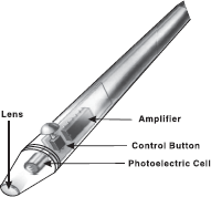
Figure 4.11 Inside a Light pen
Touch Screen: A touch screen is a special kind of input device that allows the direct selection of a menu item or the desired icon with the touch of finger (see Figure 4.12). Essentially, it registers the input when a finger or other object is touched to the screen. It is normally used when information has to be accessed with minimum effort. However, it is not suitable for input of large amounts of data. Typically, it is used in information-providing systems like hospitals, airlines and railway reservation counters, amusement parks, and so on.
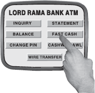
Figure 4.12 Touch Screen
How does a touch screen work? A basic touch screen has three main components: a touch sensor, a controller and a software driver (see Figure 4.13). The touch sensor/ panel is a clear glass panel with a touch responsive surface. It is placed over a display screen so that the responsive area of the panel covers the viewable area of the video screen. There are several different touch sensor technologies in the market today, each using a different method to detect touch input. These methods are optical, acoustical and electrical. In the optical method, infrared beams interlace the surface of the screen, and when a light beam is broken, that particular location is recorded. In the acoustical method, ultrasonic acoustic waves pass over the surface of the screen, and when the wave signals are interrupted by some contact with the screen, the location is recorded. In the electrical method, the panel has an electrical current running through it and touching the screen causes a voltage change, which is used to determine the location of the touch to the screen.
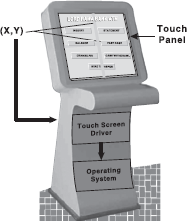
Figure 4.13 Working of Touch Screen
The controller connects the touch sensor and the computer. It takes information from the touch sensor and translates it into information that a computer can understand. The driver is a software update for the computer system that allows the touch screen and computer to work together. It tells the operating system how to interpret the touch event information that is sent from the controller.
Trackpad: Trackpad (also referred to as touchpad) is a stationary pointing device that works by sensing the movement of fingers across a small sensitive surface (1.5 or 2 inches) and translating them into the pointer movement on the screen (see Figure 4.14). It is generally used in laptops but can also be connected to a PC through a cord. It is also equipped in personal digital assistants (PDAs) and media players such as the iPod. Typically, a trackpad also consists of two or three buttons which work as mouse buttons. Many trackpads are also strike sensitive, that is, the user can tap on the trackpad to perform operations like selecting an object, maximizing/ minimizing the window, etc.
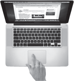
Figure 4.14 Trackpad
Note: The device manufactured by Apple is referred to as Trackpad while the device manufactured by others is known as Touchpad.
How does a trackpad work? A trackpad consists of several layers: the top layer is the rubber layer on which you move the finger, beneath this layer are two more layers consisting of horizontal and vertical rows of electrodes. The rows of electrodes do not touch each other; rather they are separated by a non-conductive, dialectic material. The layers of electrodes are charged (one with a positive electrical charge and the other with a negative charge) by alternating current (AC), and as a result an electric field is created between them. The strength of mutual capacitance of the electric field is sampled by the integrated circuits to which the layers of electrodes are connected.
As a finger approaches the top layer of the trackpad, its presence causes the change in capacitances where the electrodes cross over. The capacitance is most affected at the closest intersection point of electrodes under the position where the centre of the finger is touching. By reading the capacitances of closest intersections, the trackpad identifies the cursor position on the screen. These capacitances are measured about 100 times per second. As the finger is moved, the changes in measurements are translated into movement of the cursor on the screen.
4.2.3 Speech Recognition
Speech recognition is one of the most interactive systems to communicate with the computer. The user can simply instruct the computer, with the help of a microphone (along with a speech recognition software), to perform a task (Figure 4.15). It is the technology by which sounds, words or phrases spoken by humans are converted into digital signals, and these signals are transformed into computer-generated text or commands. Most speech recognition systems are speaker-dependent so they must be separately trained for each individual user. The speech recognition system “learns” the voice of the user, who speaks isolated words repeatedly. Then, these voiced words are recognizable in the future.
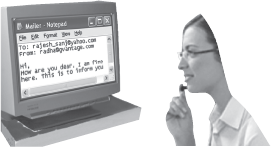
Figure 4.15 Speech Recognition
Speech recognition is gaining popularity in the corporate world among non-typists, people with disabilities, and business travellers who record information for later transcription. The computer-based speech-recognition systems can be used to create text documents such as letters or e-mails, to browse the Internet, and to navigate among applications by voice commands. They have relatively high accuracy rates. They allow the user to communicate with the computer directly without using a keyboard or a mouse. However, as compared to other input devices, the reliability of the speech recognizer is lesser. Sometimes, it is unable to differentiate between two similar sounding words such as see and sea. It is also not suitable for noisy places.
How does speech recognition work? A speech recognition system consists of a number of components, and together they convert spoken human words into computer text and commands. The system works like this: when a person speaks, the speech recognition software captures the sound through a microphone and converts it into a digital signal. The signals coming out from the microphone are analog waves. These analog waves are converted into digital signals by the computer's sound card. The speech recognition software analyses the digital pattern to find matches with known sounds contained in a database, and then passes the recognized words to an application such as Microsoft Word or WordPerfect as illustrated in Figure 4.16. Part of that database consists of predefined sound patterns—a one-size-fits-all vocabulary for recognizing speech from as many different voices as possible. The rest is built when a user “trains” the software by repeating keywords so it can recognize the user's distinctive speech patterns.
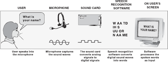
Figure 4.16 Speech Recognition System
4.2.4 Digital Camera
A Digital camera, as shown in Figure 4.17, stores images digitally rather than recording them on a film. Once a picture has been taken, it can be transferred to a computer system and then manipulated with an image editing software, and printed. The big advantage of digital cameras is that making photos is both inexpensive and fast because there is no film processing.
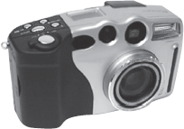
Figure 4.17 Digital Camera
How does a digital camera work? The key difference between a digital camera and a film-based camera is that the digital camera does not have a film; instead, it has a sensor that converts light into electrical charges. The image sensor employed by most digital cameras is a charge-coupled device (CCD). Some low-end cameras use complementary metal oxide semiconductor (CMOS) technology. The CCD is a collection of tiny light-sensitive diodes, which convert photons (light) into electrons (electrical charge). These diodes are called photosites. Concisely, each photosite is sensitive to light. The brighter the light that hits a single photosite, the greater the electrical charge that will accumulate at that site. In order to digitize the information, the signal must be passed through an analog-to-digital converter (ADC). The ADC converts that information to binary form and sends it to a digital signal processor (DSP). The DSP adjusts the image details, compresses the information and sends it to the camera's storage medium from where it is transferred to the computer's storage through a cable (Figure 4.18).
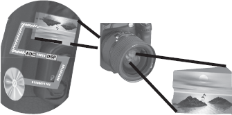
Figure 4.18 Working of a Digital Camera
4.2.5 Webcam
A webcam (short form of web camera) is a portable video camera, which captures live video or images that may be viewed in real time over a network or the Internet. It is just a small digital camera that is either built in your computer (in most laptops) or can be connected through a USB port (see Figure 4.19). It is normally placed on top of the PC monitor or laptop to capture images of the user while he/she is working on the computer.
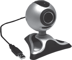
Figure 4.19 Webcam
Nowadays, a wide variety of webcams are available, and according to their varied capabilities and features, they are classified into two categories, namely, streaming and snapshot. A streaming webcam captures moving images (about 30 images per second), thus creating a streaming video—a web video that plays on the computer immediately as its data arrive via network; the recipient need not download the video. However, a high-speed Internet connection is needed to transfer the video smoothly, and the image quality is also comparatively poor. On the other hand, a snapshot webcam captures only still images (usually, once every 30 seconds) and refreshes it continuously. It produces better quality images and is easier to configure than streaming videos.
THINGS TO REMEMBER
Webcam vs. Digital Camera
A digital camera contains a memory card to store the images while a webcam does not have any in-built memory; it just captures the images and sends them over the network immediately. Also, a webcam is designed to capture low-resolution images (about 10 times less than a digital camera) so that they can be transmitted through the network easily and quickly.
The popularity of webcams is increasing everyday due to their unlimited uses. The most popular use of webcams is in videoconferencing to provide real-time communication where groups of people can see and interact with each other. It can be used with various messenger programs like Yahoo and Windows Live Messenger where you can share your videos while instant messaging with somebody. It is also being used in educational institutions to conduct distance-learning activities; one can attend the classes sitting at home only.
Webcams are cheap, compact and are easy to install and use. They are affordable because of their low manufacturing cost. However, a major drawback of using webcams is that they produce only real-time images and cannot be used unless attached with the PC. Some webcams also comprise advanced features such as automatic lightning controls, automatic face tracking and autofocus, which increase their cost.
4.2.6 Scanners
There are a number of situations when some information (picture or text) is available on paper and is needed on the computer for further manipulation. A scanner is an input device that converts a document into an electronic format that can be stored on the disk. The electronic image can be edited, manipulated, combined and printed by using the image editing software. Scanners are also called optical scanners as they use a light beam to scan the input data.
Note that most scanners come with a utility program that allow them to communicate with the computer and save the scanned images as a graphic files on the computer. Moreover, they can store images in both greyscale and colour mode. The two most common types of scanners are hand-held scanners and flatbed scanners.
Hand-held Scanner: A hand-held scanner consists of LEDs, which are placed over the document to be scanned (Figure 4.20). This scanner performs the scanning of the document very slowly from the top to the bottom with its light on. In this process, all the documents are converted and then stored as images. While working, the scanner is dragged very steadily and carefully over the document at a constant speed without stopping or jerking in order to obtain best results. Hand-held scanners are widely used where high accuracy is not of much importance. The size of the hand-held scanners is small. They come in various resolutions, up to about 800 dpi (dots per inch) and are available in either greyscale or colour. Furthermore, they are used when the volume of the documents to be scanned is low. These devices read the data on price tags, shipping labels, inventory part numbers, book ISBNs and so on.

Figure 4.20 Hand-held Scanner
How does a hand-held scanner work? When a hand-held scanner's scan button is pressed, an LED illuminates the document underneath it. An inverted angled mirror directly over the scanner's window reflects the image onto the scanner's lens, which is located at the back of the scanner. The lens focuses a single line of the image onto a Charged Coupled Device (CCD), which contains a row of light detectors. As the light shines through these detectors, each of them records the amount of light as a voltage that corresponds to white, black and grey or to a colour. These voltages are sent to a specialized analog chip, which corrects any colour detection error. After that, a single line image is passed to an Analog to Digital Converter (ADC), which converts the analog signals into binary forms that can be sent to the computer (see Figure 4.21). The converter clears itself of the data so that it can receive the next line of the image.
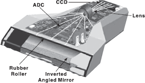
Figure 4.21 Inside a Hand-held Scanner
Flatbed Scanner: A flatbed scanner looks similar to a photocopier machine. It consists of a box containing a glass plate on its top and a lid that covers the glass plate (Figure 4.22). This glass plate is used for placing the document to be scanned. The light beam is placed below the glass plate and when it is activated, it moves horizontally from left to right. After scanning one line, the light beam moves in order to scan the next line and the procedure is repeated until all the lines are scanned. Scanning an A4 size document takes about 20 seconds. These scanners can scan black and white as well as colour images. Flatbed scanners are larger in size and more expensive than hand-held scanners. However, they usually produce better quality images because they employ better scanning technology.
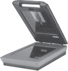
Figure 4.22 Flatbed Scanner
How does a flatbed scanner work? To scan a document, it is placed on the glass plate and the cover is closed. A lamp is used to illuminate the document. The scan head (mirrors, lens, filter and CCD array constitutes a scan head) is moved slowly across the document by a belt that is attached to a stepper motor. The head is attached to a stabilizer bar to ensure that there is no wobble or deviation in the pass. In scanning terms, a pass means that the scan head has completed a single complete scan of the document. The image of the document is reflected by an angled mirror to another mirror. Each mirror is slightly curved to focus the image it reflects onto a smaller surface. The last mirror reflects the image onto a lens. The lens focuses the image through a filter on the CCD array (Figure 4.23).
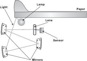
Figure 4.23 Working of a Flatbed Scanner
Some scanners use a three-pass scanning method. Each pass uses a Figure 4.23 Working of a Flatbed Scanner different colour filter (red, green or blue) between the lens and CCD array. After the three passes are completed, the scanner software assembles the three filtered images into a single full-colour image. Nowadays, most scanners use the single-pass method. The lens splits the image into three smaller versions of the original image. Each smaller version passes through a colour filter (either red, green or blue) onto a discrete section of the CCD array. The scanner combines the data from the three parts of the CCD array into a single full-colour image, which is then sent to the computer.
4.2.7 Optical Character Recognition
As stated earlier, a scanner converts an input document into an electronic format that can be stored on the disk. If the document to be scanned contains an image, it can be manipulated using image editing software. However, if the document to be scanned contains text, you need an optical character recognition (OCR) software. This is because when the scanner scans a document, the scanned document is stored as a bitmap in the computer's memory. The OCR software translates the bitmap image of text to the ASCII codes that the computer can interpret as letters, numbers and special characters.
Because of OCR, data entry becomes easier, error-free and less time consuming. However, it is very expensive and if the document is not typed properly, it will become difficult for the OCR to recognize the characters. Furthermore, except for tab stops and paragraph marks, most document formatting is lost during text scanning. The output from a finished text scan will be a single column editable text file. This text file will always require spell checking and proof reading as well as re-formatting to get the desired final layout.
How does an OCR work? All OCR systems include a scanner for reading text and sophisticated software for converting the text into machine-readable form (Figure 4.24). During OCR processing, the text is analysed for light and dark areas in order to identify each alphabetic letter or numeric digit. When a character is recognized, it is converted into an ASCII code. There are two basic methods used for OCR: matrix matching and feature extraction. The matrix matching technique compares what the OCR scanner sees as a character with a library of character matrices or templates. When an image matches one of these prescribed matrices of dots within a given level of similarity, the computer labels that image as the corresponding ASCII character. Feature extraction OCR does not require strict matching to prescribed templates. This method varies depending on how much “computer intelligence” is applied by the manufacturer. The computer looks for general features such as open areas, closed shapes, diagonal lines and line intersections. This method is much more versatile than matrix matching. At the end of the OCR processing, the final information can be saved in a number of different formats—text or rich text format (RTF).
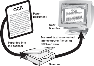
Figure 4.24 An OCR System
4.2.8 Optical Mark Recognition
Optical mark recognition (OMR) is the process of detecting the presence of intended marked responses. A mark registers significantly less light than the surrounding paper. Optical mark reading is done by a special device known as optical mark reader. In order to be detected by the OMR reader, a mark has to be positioned correctly on the paper and should be significantly darker than the surrounding paper. The OMR technology enables a high-speed reading of large quantities of data and transferring this data to a computer without using a keyboard. Generally, this technology is used to read answer sheets (objective type tests). In this method, special printed forms/documents are printed with boxes, which can be marked with a dark pencil or ink (Figure 4.25). These forms are then passed under a light source and the presence of dark ink is transformed into electric pulses, which are transmitted to the computer.
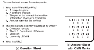
Figure 4.25 Questionnaire Using OMR Marks
OMR has a better recognition rate than OCR because fewer mistakes are made by machines to read marks than in reading handwritten characters. Large volumes of data can be collected quickly and easily without the need for specially trained staff. Usually, an OMR reader can maintain a throughput of 1500 to 10,000 forms per hour. However, the designing of documents for optical mark recognition is complicated and the OMR reader needs to be reprogrammed for each new document design. OMR readers are relatively slow because the person putting marks on the documents must follow the instructions precisely. Any folding or dirt on a form may prevent the form from being read correctly. In addition, it requires accurate alignment of printing on forms and needs a paper of good quality.
How does an OMR work? To make an OMR system work, any of the following methods of mark reading can be used.
- The first method is based on the conductivity of graphite in order to determine the presence of a pencil mark. The marks must be made only in pencil because the number of magnetic particles in the lead pencils is large.
- The second method is based on the reflection of light. In this, a thin beam of light is directed on the surface of the paper. When a lesser amount of light is transmitted through the dot, the filled box can be recognized. OMR can evaluate only those documents which are printed with the marked positions in the specified areas.
OMR is traditionally performed using the reflective light method where a beam of light is reflected on a sheet with marks to capture the reflection (presence of a mark) or absence of reflection (absence of a mark). The OMR data entry system converts the information about the presence or absence of marks into a computer data file. A simple pen or pencil mark is made on the form to indicate each selected response such as answers to survey questions. The completed forms are scanned by an optical mark reader, which detects the presence of a mark by measuring the reflected light. The OMR reader then interprets the pattern of marks into a data record and sends this to a computer for storage, analysis and reporting.
4.2.9 Magnetic-ink Character Recognition
You must have seen special magnetic encoding using characters printed on the bottom of a cheque (Figure 4.26). The characters are printed using special ink, which contains iron particles that can be magnetized. To recognize these magnetic ink characters, a Magnetic ink character reader (MICR) is used. It reads the characters by examining their shapes in a matrix form and the information is then passed on to the computer.
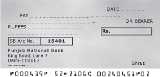
Figure 4.26 Cheque Number Written in MICR Font
The banking industry prefers MICR to OCR as MICR gives extra security against forgeries such as colour copies of payroll cheques or hand-altered characters on a cheque. If a document has been forged, say a counterfeit check produced using a colour photocopying machine, the magnetic-ink line will either not respond to magnetic fields, or will produce an incorrect code when scanned using a device designed to recover the information in the magnetic characters. The reading speed of the MICR is also higher. This method is very efficient and time saving for data processing.
4.2.10 Bar Code Reader
Bar code is a machine-readable code in the form of a pattern of parallel vertical lines of varying widths. It is commonly used for labelling goods that are available in super markets and numbering books in libraries. This code is sensed and read by a bar code reader using reflective light (Figure 4.27). The information recorded in the bar code reader is then fed into the computer, which recognizes the information from the thickness and spacing of bars. Bar code readers are either hand-held or fixed-mount. Hand-held scanners are used to read bar codes on stationary items. With fixed-mount scanners, items having a bar code are passed by the scanner by hand, as in retail scanning applications or by conveyor belts in many industrial applications.
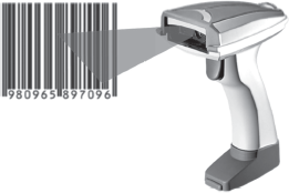
Figure 4.27 Bar Code Reader
FACT FILE
Bar Code Data
The bar code data is just reference numbers, which the computer use to look up associated record file(s), which contain descriptive information. For example, the bar codes found on food items do not contain the price or other description; instead the bar code has a product number in it. When read by a bar code reader and transmitted to the computer, the computer finds the disk record file(s) associated with that item number. This file contains the price, vendor name and other information.
Bar code data correction systems provide enormous benefits for just about every business with a bar code data-collection solution; capturing data is faster and more accurate. A bar code scanner can record data five to seven times faster than a skilled typist. A bar code data entry has an error rate of about 1 in 3 million. Bar coding also reduces cost in terms of labour and revenue losses resulting from data collection errors. Bar code readers are widely used in supermarkets, department stores, libraries and other places. You must have seen bar code on the back cover of certain books and greeting cards. Retail and grocery stores use a bar code reader to determine the item being sold and to retrieve the item price from a computer system.
Bar code scanners are electro-optical systems that include a means of illuminating the symbol and measuring reflected light. The light waveform data are converted from analog to digital, in order to be processed by a decoder, and then transmitted to the computer software. The process begins when a device directs a light beam over a bar code. The device contains a small sensory reading element, called sensor, which detects the light being reflected back from the bar code, and converts light energy into electrical energy. The result is an electrical signal that can be converted into alphanumeric data. The pen in the bar code unit reads the information stored in the bar code and converts it into a series of ASCII characters by which the operating system gets the information stored in the bar code.
4.3 TYPES OF OUTPUT DEVICES
Output is data that have been processed into useful information. It can be displayed or viewed on a monitor, printed on a printer, or listened through speakers or a headset. Generally, there are two basic categories of output: the output which can be readily understood and used by humans, and which is stored on secondary storage devices so that the data can be used as input for further processing. The output which can be easily understood and used by human beings are of the following two forms:
- Hard Copy: The physical form of output is known as hard copy. In general, it refers to the recorded information copied from a computer onto paper or some other durable surface such as microfilm. Hard copy output is permanent and a relatively stable form of output. This type of output is also highly portable. Paper is one of the most widely used hard copy output media. The principal examples are printouts, whether text or graphics from printers.
- Soft Copy: The electronic version of an output, which usually resides in computer memory and/or on disk, is known as soft copy. Unlike hard copy, soft copy is not a permanent form of output. It is transient and is usually displayed on the screen. This kind of output is not tangible, that is, it cannot be touched. Soft copy output includes audio and visual form of output, which is generated using a computer. In addition, textual or graphical information displayed on a computer monitor is also a soft copy form of output.
Based on the hard copy and soft copy outputs, the output devices are classified into hard copy and soft copy output devices. Printers, plotters and microfilms are the most commonly used hard copy output devices while monitors, voice response systems, projectors, electronic whiteboards, and headphones and headsets are some commonly used soft copy output devices.
4.3.1 Printers
Ever since the dawn of computer age, producing printed output on paper has been one of the computer's principal functions. A printer prints information and data from the computer onto paper. Generally, the printer prints 80 or l32 columns of characters in each line, and prints either on single sheets or on a continuous roll of paper, depending upon the printer itself. The quality of a printer is determined by the clarity of a print it can produce, that is, its resolution. Resolution is used to describe the sharpness and clarity of an image. The higher the resolution, the better the image. For printers, the resolution is measured in dpi (dots per inch). The more the dpi, the better will be the quality of image. The dots are so small and close together that they project the image as a solid one. If a printer has a resolution of 600 dpi, it means that the printer is capable of printing 360,000 dots per square inch.
Printers are divided into two basic categories: impact printers and non-impact printers. As their names specify, impact printers work by physically striking a head or needle against an ink ribbon to make a mark on the paper. This includes dot matrix printers, daisy wheel printers and drum printers. In contrast, ink-jet and laser printers are non-impact printers. They use techniques other than physically striking the page to transfer ink onto the page.
Dot Matrix Printer: Dot matrix printer (also known as the wire matrix printer) uses the oldest printing technology and it prints one character at a time (Figure 4.28). It prints characters and images as pattern of dots. The speed of dot matrix printers is measured in characters per second (cps). Most dot matrix printers offer different speeds depending on the quality of print desired. The speed can vary from about 200 to over 500 cps. The print quality is determined by the number of pins (the mechanisms that print the dots), which can vary from 9 to 24. The more pins per inch, the Figure 4.28 Dot Matrix higher the print resolution. The best dot matrix printers Printer (24 pins) can produce near letter-quality-type image. Most dot matrix printers have a resolution ranging from 72 to 360 dpi.
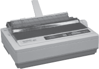
Figure 4.28 Dot Matirx Printer
Dot matrix printers are inexpensive and have low operating costs. These printers are able to use different types of fonts, different line densities and different types of paper. Many dot matrix printers are bi-directional, that is, they can print the characters from either direction— left or right. The major limitation of the dot matrix printer is that it prints only in black and white. In addition, as compared to printers like laser printers, they produce low to medium quality printing. The image printing ability is also very limited. These printers may not be able to print graphic objects adequately but can handle applications such as accounting, personnel and payroll very well. Dot matrix printers are commonly used in low-cost, low-quality applications like cash registers. These printers are limited to situations where carbon copies are needed and the quality is not too important.
How does a dot matrix printer work? The technology behind dot matrix printing is quite simple as shown in Figure 4.29. The paper is pressed against a rubber-coated cylinder and is pulled forward as printing progresses. The printer consists of an electro-magnetically driven print head, which is made up of numerous print wires (pins). The characters are formed by moving the electro-magnetically driven print head across the paper, which strikes the printer ribbon situated between the paper and print head pin. As the head stamps onto the paper through the inked ribbon, a character is produced that is made up of these dots. These dots seem to be very small for the normal vision Matrix Printer and appear like solid human-readable characters.
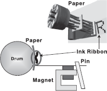
Figure 4.29 Working of Dot Matrix Printer
Daisy Wheel Printer: The major drawback of the dot matrix printer is that the pattern of dots that make up each character is visible on the print produced by it, making it look unprofessional. If you need a printer that can produce professional letter quality documents, you need a daisy wheel printer. The daisy wheel printer is named so because the print head of this printer resembles a daisy flower, with printing arms that appear like the petals of the flower (see Figure 4.30). These printers are commonly referred to as letter quality printers as the print quality is as good as that of a high-quality typewriter.
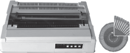
Figure 4.30 Daisy Wheel Printer
Daisy wheel printers produce high-resolution output and are more reliable than dot matrix printers. They can have speeds up to 90 cps. These printers are also called smart printers because of their bi-directional printing and built-in microprocessor control features. However, daisy wheel printers give only alphanumeric output. They cannot print graphics and cannot change fonts unless the print wheel is physically replaced. These printers are usually very slow because of the time required to rotate the print wheel for each character desired. Daisy wheel printers are slower and more expensive than dot matrix printers. However, if the appearance of the correspondence is important and you do not need graphics, a daisy wheel printer is a better choice.
How does a daisy wheel printer work? These printers have print heads composed of metallic or plastic wheels. A raised character is placed on the tip of each of the daisy wheel's “petals”. Each petal has an appearance of a letter (upper case and lower case), number or punctuation mark on it. To print, the print wheel is rotated around until the desired character is under the print hammer. The petal is then struck from behind by the print hammer, which strikes the character, pushing it against the ink ribbon, and onto the paper, creating the character (see Figure 4.31).
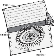
Figure 4.31 Working of Daisy Wheel Printer
Drum Printer: The dot matrix and daisy wheel printers are character or serial printers, that is, they print one character at a time. However, a drum printer (shown in Figure 4.32) is a line printer, that is, it can print a line in a single operation. Generally, a line printer is used because of its speed as it uses special tractor-fed paper with pre-punched holes along each side. This arrangement allows a continuous high-speed printing. Its printing speed varies from 300 lines to 2000 lines per minute with 96–160 characters on a 15-inch line. Although such printers are much faster than character printers, they tend to be quite loud, have limited multi-font capability and often produce lower print quality than most recent printing technologies. Line printers are designed for heavy printing applications. For example, in businesses where enormous amounts of materials are printed, the low-speed character printers are very slow; therefore, the users need high-speed line printers. Although, drum printers have high speed of printing, they are very expensive and their character fonts cannot be changed. Moreover, the strike of the hammer should be precise. A single mistimed strike of the hammer may lead to wavy and slightly blurred printing.
Figure 4.32 Drum Printer
How does a drum printer works? The basics of a line printer, like the drum printer, are similar to those of a serial printer except that multiple hammers strike multiple type elements against the paper almost simultaneously, so that an entire line is printed in one operation. A typical arrangement of a drum printer involves a large rotating drum mounted horizontally and positioned in front of a very wide inked Figure 4.33 Working of Drum Printer ribbon, which, in turn, is positioned in front of the paper itself (see Figure 4.33). The drum contains characters moulded onto its surface in columns around its circumference; each column contains a complete set of characters (letters, digits, etc.) running around the circumference of the drum. The drum spins continuously at high speed when the printer is operating. In order to print a line, hammers positioned behind the paper ram the paper against the ribbon and against the drum beyond it at exactly the right instant, such that the appropriate character is printed in each column as it spins past on the drum. Once every column has been printed, the paper is advanced upward so that the next line can be printed.
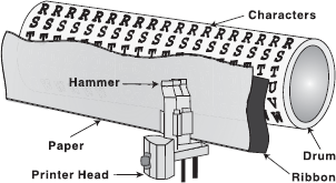
Figure 4.33 Working of Drum Printer
Ink-jet Printer: The most common type of printer found in homes today is the ink-jet printer (see Figure 4.34). An ink-jet printer is a printer that places extremely small droplets of ink onto paper to create an image. Being a non-impact printer, it does not touch the paper while creating an image. Instead, it uses a series of nozzles to spray drops of ink directly onto the paper. Inkjets were originally manufactured to print in monochrome (black and white) only. However, the print head has now been expanded and the nozzles increased to accommodate cyan (C), magenta (M), yellow (Y) and black (K). This combination of colours is called CMYK. It allows for printing images with nearly Figure 4.34 Ink-jet Printer the same quality as a photo development lab using certain types of coated paper.
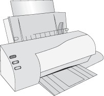
Figure 4.34 Ink-Jet Printer
Ink-jet printers are costlier than dot matrix printers and the quality is much better. These printers can print any shape of character, which a user can specify, as they produce printed output as patterns of tiny dots. This allows the printer to print many special characters, different sizes of prints, and enables it to print graphics such as charts and graphs. Ink-jet printers typically print with a resolution of 600 dpi or more. Due to the high resolution, these printers produce high quality graphics and text printouts. They are also affordable, which appeals to small businesses and home offices. These printers print documents at a medium pace but slow down if printing a document with multi-colours. These printers can print about six pages a minute and can be programmed to print symbols such as Japanese or Chinese characters.
How does an ink-jet printer work? An ink-jet printer places extremely small droplets of ink onto the paper to create a character or an image. It has a print cartridge with a small series of electrically heated chambers. These chambers are attached to the print head with a series of small nozzles that spray ink onto the surface of the paper. As the print head moves back and forth across the page, the software gives instructions regarding the type and the quantity of colours. It also tells the position where the dots of ink should be “sprayed”. There are two main ways to drop the ink droplets, namely, the bubble-jet and piezoelectric technology (see Figure 4.35). Bubble-jet printers use heat to fire ink onto the paper. There are three main stages with this method. The squirt is initiated by heating the ink to create a bubble until the pressure forces it to burst and hit the paper. The bubble then collapses as the element cools, and the resulting vacuum draws ink from the reservoir to replace the ink that was ejected. Piezoelectric technology uses a piezo crystal at the back of the ink reservoir. It flexes when an electric current flows through it. Therefore, whenever a dot is required, a current is applied to the piezo element, the element contracts and in doing so forces a drop of ink out of the nozzle.
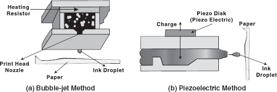
Figure 4.35 Spraying Techniques of Ink-jet Printer
Laser Printer: A laser printer provides the highest quality text and images for personal computers today (see Figure 4.36). It is a very fast printer, which operates on the same principle as that of a photocopy machine. Most laser printers can print text and graphics with a very high quality resolution. They are also known as page printers because they process and store the entire page before they actually print it. They produce sharp, crisp images of both text and graphics, providing resolutions from 300 to 2400 dpi. Today, the resolution of most printers is 600 dpi. They are quiet and fast, are able to print 4–32 text-only pages per minute for individual microcomputers and up to 200 pages per minute for mainframes. Laser printers can print in excess of 2000 lines per minute. Furthermore, they can print in different fonts, that is, type styles and sizes. Laser printers are often faster than ink-jet printers but are more expensive to buy and maintain than the other printers. The cost of these printers depends on a combination of costs of paper, toner replacement, and drum replacement. These printers are useful for volume printing because of their speed.
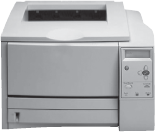
Figure 4.36 Laser Printer
How does a laser printer work? The core component of laser printing system is the photoconductive drum. A rotating mirror inside the printer causes a beam of laser to sweep across the photoconductive drum. Initially, the beam of laser charges the photoconductive drum positively. When the charged photoconductor is exposed to an optical image through a beam of light to discharge, a latent or invisible image is formed. At the point where the laser strikes the surface of the drum, it creates a dot of positive charge. These points are represented by black dots, which will be printed on the paper. After this, the printer coats the drum with a container, which contains a black powder called toner. This toner is negatively charged, and so it clings to the positive areas of the drum surface. When the powder pattern gets fixed, the drum is rotated and the paper is fed into the drum surface via a pressure roller. This pressure roller transfers the black toner onto the paper. Since the paper is moving at the same speed as the drum, the paper picks up the image pattern precisely. Finally, the printer passes the paper through the fuser, a pair of heated rollers. As the paper passes through these rollers, the loose toner powder gets melted and fuses with the fibres in the paper. The paper is then brought out of the printer (see Figure 4.37).
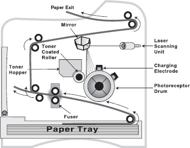
Figure 4.37 Working of a Laser Printer
Hydra Printer: Hybrid document reproduction apparatus (HYDRA) printer, popularly known as all-in-one printer, is a device that consolidates the capabilities of multiple devices in one machine (see Figure 4.38). It may include some or all of the devices like printer, scanner, photocopier and fax machine. Apart from these devices, some hydra printers contain memory card slots which facilitate easier printing of photos and also have the in-built wireless capabilities that make Figure 4.38 Hydra Printer sharing of this printer with other systems easier.
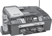
Figure 4.38 Hydra Printer
Following are the features that must be considered to evaluate these printers:
- Print speed
- Maximum resolution
- Memory card compatibility
- Scanner resolution
- Fax speed
Hydra printers are useful for small organizations due to their small size, less space requirement and cost effectiveness. The cost of these printers depend on the technology (inkjet or laser) being used. They save power to a great extent as only one power outlet is required for performing various operations. They are easy to install and maintain and have easy-to-use GUI (graphical user interface) that help users to understand their functions easily.
THINGS TO REMEMBER
Raster versus Vector
A grid of pixels defines raster; each pixel is a different colour to make an entire image. Vector graphics, on the other hand, are not constricted to a grid format. Such graphics are given instructions by the computer about how the objects should be shaped and their relative size, making them resolution-independent. Hence, they are readily scaleable without distortion. Vector images are used for charts and graphs, and other graphics that must have sharp lines when scaled to various sizes. Raster images are used for creating subtle gradations of shades and colour such as in a photograph.
4.3.2 Plotters
A plotter is a pen-based output device that is attached to a computer for making vector graphics, that is, images created by a series of many straight lines. It is used to draw high-resolution charts, graphs, blueprints, maps, circuit diagrams and other line-based diagrams. It is similar to a printer, but it draws lines using a pen. As a result, it can produce continuous lines, whereas a printer can only simulate lines by printing a closely spaced series of dots. Multicolour plotter uses different coloured pens to draw different colours. Colour plots can be made by using four pens (cyan, magenta, yellow and black) and need no human intervention to change them.
Being vector-based, a plotter tends to draw much crisper lines and graphics. The lines drawn by these devices are continuous and very accurate. However, the plotter is considered a very slow output device because it requires excessive mechanical movement to plot. Furthermore, it is unable to produce solid fills and shading. Plotters are relatively expensive as compared to printers but can produce more printouts than standard printers. They are mainly used for Computer Aided Design (CAD) and Computer Aided Manufacturing (CAM) applications such as printing out plans for houses or car parts. These are also used with programs like AUTOCAD (computer assisted drafting) to give graphic outputs. As shown in Figure 4.39, there are two different types of plotters: drum plotter (where the paper moves) and flatbed plotter (where the paper is stationary).
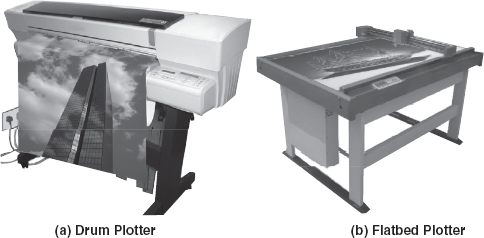
Figure 4.39 Plotters
- Drum Plotter: In drum plotters, the paper on which the design is to be printed is placed over a drum. These plotters consist of one or more pen(s) that are mounted on a carriage which is horizontally placed across the drum. The drum can rotate in either clockwise or anticlockwise direction under the control of plotting instructions sent by the computer. In case a horizontal line is to be drawn, the horizontal movement of the pen is combined with the vertical movement of the page via the drum. The curves can also be drawn by creating a sequence of very short straight lines. In these plotters, each pen can have an ink of a different colour to produce multicolour designs. Drum plotters are used to produce continuous output such as plotting earthquake activity or for long graphic output such as tall building structures.
- Flatbed Plotter: Flatbed plotters consist of a stationary, horizontal plotting surface on which paper is fixed. The pen is mounted on a carriage, which can move horizontally, vertically, leftwards or rightwards to draw lines. In flatbed plotters, the paper does not move, the pen-holding mechanism provides all the motion. These plotters are instructed by the computer on the movement of pens in the x – y coordinates on the page. These plotters are capable of working on any standard, that is, from A4 size paper to some very big beds. Depending on the size of the flatbed surface, these are used in designing of ships, aircrafts, buildings and so on. The major disadvantage of this plotter is that it is a slow output device and can take hours to complete a complex drawing.
How does a plotter work? The heart of the plotter is the printer head assembly, consisting of a horizontal bar and the pen in use, attached to the head assembly holding (see Figure 4.40). The pen can be positioned horizontally by moving the pen assembly along the bar. Vertical positioning is achieved by either moving the bar (flatbed plotter) or the paper (drum plotter). Combinations of horizontal and vertical movement are used to draw arbitrary lines and curves in a single action, in contrast to printers, which usually scan horizontally across the page. Plotters create plots by moving a pen under computer control over a drafting paper. The instructions that a plotter receives from a computer consist of a colour and beginning and end coordinates for a line. When an image is to be drawn, a specially designed holder picks up a pen and takes it over to the start position. The pen is pushed down onto the paper and dragged over the surface to produce straight or curved lines. If the product is to be in colour, the pen is then replaced with a new pen. The process continues until the image is complete.
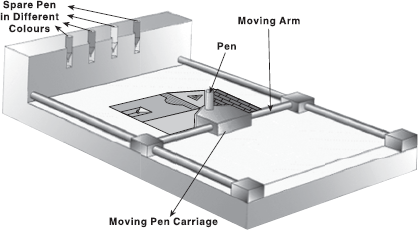
Figure 4.40 Working of Flatbed Plotter
4.3.3 Computer Output Microfilm
Computer Output Microfilm (COM) is an extremely high-speed, low-cost process, which records computer-generated information directly from the computer tape or cartridge to a miniaturized microfilm media. The microfilm product is in fiche or roll format, which can be duplicated rapidly and inexpensively. This process can produce data in microfilm form at a highly significant speed from that of a paper printer. The image area of the copy is dramatically reduced, up to 1/40 of its original size; yet, it retains its original clarity. Traditional roll microfilm is 16 mm wide, with a film image that is 1/24 of the size of the original document, often called 24x. Images are normally side-by-side on the film. Therefore, a letter size image is a little over 1/3 inch wide, and a ledger sheet can be well over 1/2 inch. Some cameras and computer output systems create an image 1/42 or 1/48 of the document's original size, with a few systems using even smaller or larger sizes. A jacket microfilm (microfiche), plastic sleeves with small pieces of film, represents individual document (cut from roll microfilm). All the documents for a particular context are placed in a single jacket, much like a file folder. Each 105 × 148 mm jacket typically has five horizontal rows, with an opening at the right end of each row where the film is inserted. Each row can hold 10–15 pages. Microfiche can be indexed in order to locate necessary information quickly and easily and have a life expectancy of more than 500 years. To retrieve the images, the microfilm images may be enlarged on a viewing screen with the help of a microfilm reader Figure 4.41 for comfortable reading.
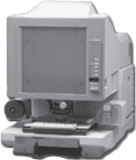
Figure 4.41 Microfilm Reader
COM results in material, space and equipment savings along with mailing costs and information retrieval savings. In addition, hard copy prints can be made without loss of detail when compared with the original document. It facilitates indexing to access information. Furthermore, it provides an inexpensive way to preserve records from a variety of electronic sources. Such records might need to be stored for long periods and referenced only occasionally. The main disadvantage, however, is that it is expensive to install COM, and microfilms cannot be read without the assistance of a special reader device. Moreover, development of secondary-storage techniques such as the use of removable, high-capacity hard disks had lessened their appeal as output and storage method.
Generally, a COM system is ideal for applications where there is a large amount of information to be retained, and therefore very useful for manuals, industrial catalogues and archives. Microfilm output is used for distribution of airline schedules, medical X-rays and lists of books in print. Banking and insurance companies, government agencies, public utilities and many other types of organizations are regular users of COM.
Creating Microfilms: Microfilms can be created in the following two ways:
- Photographic Process: It is the oldest method of creating microfilms. Essentially, it is a form of miniature photography, which uses a microfilm camera for producing microfilms. When the original documents are fed through a microfilm camera, it captures the document into a reduced-size photo. Once all the photographs are taken, the rolls of films are removed from the camera for further processing and development. The processed images can be rolled on film rolls, or cut into sections and loaded to flat microfiche holders.
- Non-photographic Process: In this process, the user can entirely avoid the film-developing process. This process uses a monitor and the computer output is read onto the magnetic tape. After this, data are printed on microfilm by using a microfilm recorder. Moreover, it is possible to couple a microfilm machine directly to a computer; therefore, the recorder can directly receive information from the computer. As the recorder projects the computer information onto the screen, a high-speed camera photographs the displayed information.
The process of creating microfilm from magnetic tape is illustrated in Figure 4.42.
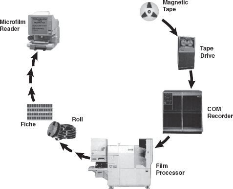
Figure 4.42 Creating Microfilm from Magnetic Tape
4.3.4 Monitor
The monitor is the most frequently used output device for producing soft-copy output. A computer monitor is a TV-like display attached to the computer on which the output can be displayed and viewed. The computer monitor can either be a monochrome display or a colour display. A monochrome screen uses only one colour (usually white, green, amber or black) to display text on contrasting background. Colour screens commonly display 256 colours at one time from a selection of over 256,000 choices. Monitors are available in various sizes like 14, 15, 17, 19 and 21 inches. The size of the display is described based on two parameters: aspect ratio and screen size (see Figure 4.43). Aspect ratio is the ratio of the width of the display screen to the height, that is, the ratio of vertical points to the horizontal points necessary to produce equal-length lines in both directions on the screen. Generally, computer displays have an aspect ratio of 4:3. Like televisions, screen sizes are normally measured diagonally (in inches), the distance from one corner to the opposite corner.
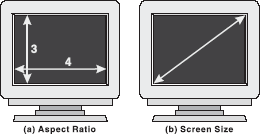
Figure 4.43 Aspect Ratio and Screen Size
Sometimes, while watching television, you may notice that the picture looks a bit blurred. The reason behind this is that the displayed image is not solid but is created by the configurations of dots. These dots are known as picture elements, pels, or simply pixels. The golden rule of a sharp image is that the more the pixels, the sharper the picture. The screen clarity depends on three basic qualities:
- Resolution: It refers to the number of pixels in the horizontal and vertical directions on the screen. In medium-resolution graphics, pixels are large, whereas in high-resolution graphics, pixels are small. The average CRT display is currently 800 × 600 or 1024 × 768. The more dots, or pixels, available to create the image, the sharper it will be. Therefore, a resolution of 1024 × 768 will produce sharper images (for example, smaller icons and more information) than one of 640 × 480.
- Dot Pitch: It is the measurement of the diagonal distance between two like-coloured (red, green or blue) pixels on a display screen. It is measured in millimetres and common dot pitches are .51 mm, .31 mm, Pixel .28 mm, .27 mm, .26 mm and .25 mm. The Figure 4.44 Dot Pitch smaller the dot pitch, the sharper will be the image when displayed on the monitor. Generally, a dot pitch of less than .31 mm provides clear images. Multimedia and desktop-publishing users typically use .25 mm dot-pitch monitors (see Figure 4.44).
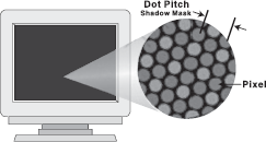
Figure 4.44 Dot Pitch
- Refresh Rate: It is the number of times per second the pixels are recharged so that their glow remains bright. Normally, screen pixels are made from phosphor. An electron beam strikes the phosphor and causes it to emit light, resulting in the display of the image. However, it needs to be Refreshed periodically because the phosphors hold their glow for just a fraction of a second. The Refresh rate for a monitor is measured in Hertz (Hz) and varies from 60 to 75 Hz. A Refresh rate of 60 Hz means image is redrawn 60 times a second. The higher the Refresh rate, the more solid the image looks on the screen, that is, it does not flicker.
Colour Depth: Colour depth, also referred to as bit depth, refers to the number of bits assigned to each pixel in the image and the number of colours that can be created from those bits. In simple words, it refers to the number of colours that a monitor can display. Different colour depths depend on the amount of display memory dedicated to each pixel. One byte is used to represent 256 colours for each pixel, 16 bits (or 2 bytes) per pixel allows up to 65535 colours, and 24-bit (or 3 bytes) colour can display 16.8 million different colours per pixel. 8-bit colour is better known as pseudo colour, 16-bit mode as high colour, and 24-bit mode is called true colour. A video display unit consists of a video card or adapter that is fitted into an expansion slot and a compatible visual display, which is compatible with the video adapter. The combination of the display modes supported by the graphics adapter and the colour capability of the monitor determine how many colours can be displayed.
Cathode Ray Tube Monitors: Nowadays, most computer monitors are based on cathode ray ube (CRT ) technology. The basic operation of these tubes is similar to that in television sets. Figure 4.45 illustrates the basic components of a CRT.
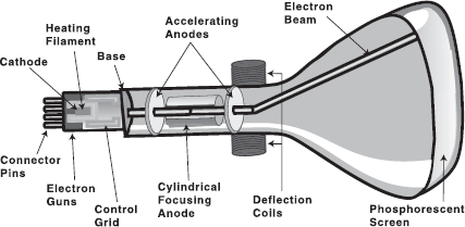
Figure 4.45 Cathode Ray Tube
A beam of electrons (cathode rays) emitted by an electron gun passes through focusing and deflection systems that direct the beam toward specified positions on the phosphor-coated screen. The phosphor then emits a small spot of light at each position contacted by the beam. When the electron beam strikes the phosphors, the light is emitted for a short period of time, this condition is known as persistence. Technically, persistence is defined as the time it takes for the emitted light from the screen to decay to 1/10 of its original intensity. Graphics monitors are usually constructed with persistence in the range of 10–60 microseconds. Since the light emitted by the phosphor fades very rapidly, some method is needed for maintaining the screen picture. One way to keep the phosphor glowing is to redraw the picture repeatedly by quickly directing the electron beam back over the same points. This type of display is called a Refresh CRT.
The primary components of an electron gun in a CRT are the heated metal cathode and a control grid. Heat is supplied to the cathode by directing a current through a coil of wire, called the filament, inside the cylindrical cathode structure. This causes electrons to be “boiled off ” the hot cathode surface. In the vacuum inside the CRT envelope, the free, negatively charged electrons are then accelerated toward the phosphor coating by a highly positive voltage. The accelerating voltage can be generated with a positively charged metal coating on the inside of the CRT envelope near the phosphor screen, or an accelerating anode can be used, as in Figure 4.45. Note that sometimes the electron gun is built to contain the accelerating anode and focusing system within the same unit.
Before reaching the phosphor-coated screen, the electrons have to be passed through the monitor's focusing system. The focusing system is initially set up to focus the electron flow into a very thin beam and then in a specific direction. Focusing can be accomplished either by electric or by magnetic fields.
When the electrons in the beams collide with the phosphor coating, their kinetic energy is absorbed by the phosphor. Some of this energy is converted into heat while rest of the energy causes the electrons in the phosphors to move up to the higher energy levels. After this, when these electrons begin to return to the ground state, they emit light at certain frequencies. These frequencies are proportionate to the energy difference between the higher state and the ground state. As a result, the image, which we see on the screen, is the combination of all the electron light emissions.
Displaying Graphics on a CRT: Nowadays, two classes of computer graphic display are used: raster scan and random scan display.
- Raster Scan Display: In this system, the electron beam is swept across the screen one row at a time from top to bottom. As the electron beam moves across each row, the beam intensity is turned ON and OFF to create a pattern of illuminated spots. The picture definition is stored in a memory area called the Refresh buffer or frame buffer, which holds the set of intensity values for all the screen points. These values are then retrieved from the Refresh buffer and “painted” on the screen one row (scan line) at a time. At the end of each scan line, the electron beam returns to the left side of the screen to begin displaying the next scan line. The return to the left of the screen, after Refreshing each scan line, is called the horizontal retrace of the electron beam. At the end of each frame, the electron beam returns to the top left corner of the screen to begin the next frame. This is known as vertical retrace (see Figure 4.46). On some raster-scan systems, each frame is displayed in two passes using an interlaced Refresh procedure. In the first pass, the beam sweeps across every other scan line from top to bottom. Then after the vertical retrace, the beam sweeps out the remaining scan lines. Interlacing of the scan lines in this way allows us to see the entire screen displayed in half the time it would have taken to sweep across all the lines at once from top to bottom. This is an effective technique for avoiding flicker, provided that adjacent scan lines contain similar display information.
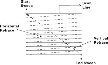
Figure 4.46 Raster Scanning
- Random Scan Display: In this system, a CRT has the electron beam directed only to the parts of the screen where a picture is to be drawn. Random scan monitors draw a picture one line at a time, and for this reason are referred to as vector, stroke-writing, or calligraphic displays. The component lines of a picture can be drawn and Refreshed by a random scan system in any specified order. Refresh rate on a random scan system depends on the number of lines to be displayed. Picture definition is stored as a set of line-drawing commands in an area of memory referred to as the Refresh display file. To display a specified picture, the system cycles through the set of commands in the display file, drawing each component line in turn. After all line drawing commands have been processed, the system cycles back to the first line command in the list. Random scan systems are designed for line drawing applications. They cannot display realistic shaded scenes.
Colour display on a CRT A CRT monitor displays colour pictures by using a combination of phosphors that emit different coloured light. By combining the emitted light from the different phosphors, a range of colours can be generated. The two basic techniques for producing colour displays with a CRT are:
- Beam Penetration: The beam-penetration method for displaying colour pictures is commonly used with random scan displays. In this system, two layers of phosphor (usually red and green) are coated on the inner side of the CRT screen. The displayed colour depends on how far the electron beam penetrates into the phosphor layers. A beam of slow electrons excites only the outer red layer while a beam of very fast electrons penetrates through the red layer and excites the inner green layer. At intermediate beam speeds, combinations of red and green light are emitted to show two additional colours— orange and yellow. The speed of the electrons, and hence the screen colour at any point, is controlled by the beam-acceleration voltage. Beam penetration is an inexpensive way to produce colour in random scan monitors. However, with this method, only four colours are possible, and the quality of pictures is not as good as other methods.
- Shadow Masking: Shadow-mask method is commonly used in raster scan systems because it produces a much wider range of colours than the beam-penetration method. A shadow-mask CRT has three phosphor colour dots at each pixel position. One phosphor dot emits a red light, another emits a green light and the third emits a blue light. This type of CRT has three electron guns, one for each colour dot, and a shadow-mask grid just behind the phosphor-coated screen. Three electron beams are deflected and focused as a group onto the shadow mask, which contains a series of holes aligned with the phosphor-dot patterns. When the three beams pass through a hole in the shadow mask, they activate a dot triangle, which appears as a small colour spot on the screen. The phosphor dots in the triangles are arranged so that each electron beam can activate only its corresponding colour dot when it passes through the shadow mask (see Figure 4.47).
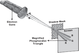
Figure 4.47 Shadow Masking
Colour variations in a shadow-mask CRT can be obtained by varying the intensity levels of the three electron beams. For example, a white (or grey) area is the result of activating all three dots with equal intensity. Yellow is produced with the green and red dots only, magenta is produced with the blue and red dots, and cyan is displayed when blue and green are activated equally.
Liquid Crystal Display Monitors: In the previous section, we discussed the most popular CRT monitors that are used as display devices. With the widespread use of smaller computers like PDAs and laptops, a new type of display, Liquid Crystal Display (LCD), has made a big impact on the computer market. LCD screens have been used for long on notebook computers but are also becoming popular as desktop monitors.
The term liquid crystal sounds like a contradiction. We generally conceive a crystal as a solid material like quartz and a liquid as water-like fluid. However, some substances can exist in an odd state that is semi-liquid and semi-solid. When they are in this state, their molecules tend to maintain their orientation like the molecules in a solid, but also move around to different positions like the molecules in a liquid. Thus, liquid crystals are neither a solid nor a liquid. Manufacturers use this amazing ability of liquid crystals to display images.
An LCD screen is a collection of multiple layers as shown in Figure 4.48. A fluorescent light source, known as the backlight, makes up the rearmost layer. Light passes through the first of two polarizing filters. The polarized light then passes through a layer that contains thousands of liquid crystal blobs aligned in tiny containers called cells. These cells are aligned in rows across the Figure 4.48 Coloured Liquid Crystal Screen screen; one or more cells make up one pixel. Electric leads around the edge of the LCD create an electric field that twists the crystal molecule, which lines the light up with the second polarizing filter and allows it to pass through.
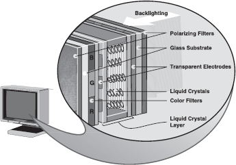
Figure 4.48 Coloured Liquid Crystal Screen
The process illustrated in Figure 4.47 is followed for a simple monochrome LCD. However, colour LCD is more complex. In a coloured LCD panel, each pixel is made up of three liquid crystal cells. In front of each of these cells, there is a red, green or blue filter. Light passing through the filtered cells creates the colours on the LCD. Nowadays, nearly every colour LCD uses a thin-film transistor (TFT), also known as an active matrix, to activate each cell (see Figure 4.49). TFT-based LCD creates sharp, bright images as compared to previous LCD technologies. The oldest of the matrix technologies, passive-matrix, offers sharp text but leaves “ghost images” on the screen when the display changes rapidly, making it less than optimal for moving video.
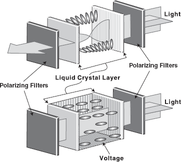
Figure 4.49 Active Matrix LCD
An LCD addresses each pixel individually. As a result, they can create sharper text than CRTs. However, LCD has only one “natural” resolution, limited by the number of pixels physically built into the display. If you want to move up to, say, 1024 by 768 LCD on an 800 by 600 LCD, you have to emulate it with software, which will work only at certain resolutions.
Differences between LCD and CRT: Although both the CRT and LCD monitors are the most frequently used types of displays in computers, they are worlds apart in terms of what is important when making a purchase decision. Here is a brief discussion of what is different about LCD monitors.
- Size: LCD is lightweight and compact, which saves desktop space as compared to a CRT.
- Resolution: LCD is designed to work in a single resolution while CRT is designed for many resolutions.
- Pixel Density: Pixel density of LCD is generally not as tight as the dot pitch in CRT but for most applications, the density is acceptable.
- Brightness: The illuminated phosphor of a CRT is not nearly as bright as what the LCD can produce with its florescent backlight.
- Power Consumption: LCD consumes significantly less power than CRT and has a low emission risk. Typically, a LCD consumes approximately half of the power of a typical CRT.
- Flicker: With CRT monitors, the goal is to get a faster Refresh rate of at least 85 Hz,but LCD monitors are designed to run at a much slower Refresh rate (usually about 60 Hz) and flicker is never an issue.
- Pixel Response Time: The time taken by a pixel to change its state is called pixel response time. CRT has extremely fast pixel response time but LCD can be quite slow. As a result, the user might see “ghost images” when there is movement on the screen. The fastest LCD monitors today have a response time of 25 milliseconds, which is still only about half the speed of a CRT monitor.
- Viewing Angle: CRT can be viewed at almost any angle but LCD is best viewed “head on”. Even when viewing an LCD head on, narrow viewing angles can appear to have inconsistent colour and brightness.
- Viewing Area: The viewing area of a CRT is usually less than its advertised area. Most 19-inch CRT monitors, for example, typically have about 18 inches of viewable area. However, the LCD monitors are measured exactly, that is, if a LCD monitor is advertised as 17.4 inch, it is the same.
- Cost: Prices for LCD screens are quite high but they are coming down. They are still much more costlier than CRT.
Other Types of Monitors: Although CRT and LCD displays are the most commonly used, other kinds of displays also exist. Some of them are as follows:
- Plasma Display: A plasma display (also known as thin-panel) is constructed by filling a gas (neon or xenon) between the two glass plates. One glass plate consists of vertical conductors and the other consists of horizontal conductors. When the voltage is applied to the pair of horizontal and vertical conductors, the gas at the intersection of two conductors glows. The advantage of plasma display is that it has the capability of producing more than 16 million colours and is lighter and less bulky than CRT. However, it is heavier than LCD display and requires more power.
- Thin-film Electroluminescent Display: This display is similar to the plasma display except the fact that the space between the glass plates is filled with phosphorescent substance (usually zinc sulfide doped with manganese) instead of gas. When high voltage is applied to the crossing conductors, the phosphoric substance at the intersection of two conductors becomes conductor and generates the electrical energy. This energy is absorbed by the manganese atoms and then released as a spot of light. The main problem with thin-film electroluminescent displays is that they require more power.
4.3.5 Voice Response System
Previously, we discussed that voice (in speech recognition) can be taken as an input by the computer system. Similarly, the computer can also give output in the form of audio. Voice response system has an audio-response device which produces audio output. These sounds are pre-recorded in a computer system. Each sound has a unique code. Whenever an enquiry is sought from the system, the computer responds in digital form which is sent to voice devices that unscramble the digital information and produces sound messages to the requesting computer.
There are two basic approaches to get a computer to talk to the user. The first is synthesis by analysis, in which the device analyses the input of an actual human voice speaking words, stores and processes the spoken sounds, and reproduce them as needed. The process of storing words is similar to the digitizing process we discussed while considering voice input. In essence, synthesis by analysis uses the computer as a digital tape recorder. The second approach to synthesizing speech is synthesis by rule, in which the device applies a complex set of linguistic rules to create artificial speech. Synthesis based on the human voice has the advantage of sounding more natural but is limited to the number of words stored in the computer.
The standard computer system can provide audio output with the addition of two components: a speech synthesizer that does the speaking and a screen reading software that tells the synthesizer what to say (see Figure 4.50). The synthesizer can be a computer card inserted into the computer or software that works with the computer's sound card. Screen reader is a software program that allows the user to control the synthesizer so that he can access text, which is displayed on the computer monitor, with combinations of keystrokes. Some screen review softwares use the standard computer keyboard keys, some use the numeric keypad, and some use special external keypads. A visually impaired user can use a screen reader to read anything on the screen. The screen reading software can even notify a user about various computer messages that “pop up” on the monitor from time to time.

Figure 4.50 Audio Output
Voice output has become common in many places like airlines, bus terminals, banks and brokerage houses. It is typically used when an inquiry is followed by a short reply (such as a bank balance or flight time). Many businesses have found other creative uses for voice output. For example, the telephone. Automatic telephone voices take surveys, inform customers that catalogue orders are ready to be picked up, and perhaps remind consumers that they have not paid their bills. Moreover, people with a total or partial speech handicap are faced with the problem of communicating their wishes and needs to others. Speech output systems are a valuable aid in this case.
4.3.6 Projector
Projectors have an important place in history, as its growth led to the first moving pictures of the late 19th century, and soon to television. They have allowed the world to share greater information pertaining to culture, technology, medicine and community. Screen image projector is an output device, which is used to project information from a computer on to a large screen, so that it can be simultaneously viewed by a large group of people. Projection display is commonly used for classrooms training or conference room or for multimedia presentations with a large audience. Like monitors, projectors provide a temporary, soft copy output.
Types of Projectors: Projectors are mainly of two types:
- LCD Projectors: LCD is the established technology used by most of the leading manufacturers. Most of today's LCD projectors contain three separate LCD glass panels, one each for red, green and blue components of the image signal being fed into the projector. As light passes through the LCD panels, individual pixels can be opened to allow light to pass, or closed to block the light. This activity modulates the light and produces the image that is projected onto the screen (see Figure 4.51).
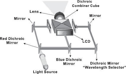
Figure 4.51 LCD Projector Display
- DLP Projectors: DLP is the acronym for digital light processing. It is a proprietary technology developed by Texas Instruments. DLP uses a single digital mirror device (DMD) chip that has thousands of tiny mirrors, each representing a single pixel. These mirrors tilt back and forth, directing the light either into the lens path to turn the pixel ON, or away from the lens path to turn it OFF and create the image (see Figure 4.52). DLP is a newer technology than LCD and is used on some of the smallest, lightest projectors currently available. DLP projectors handle video images extremely well.
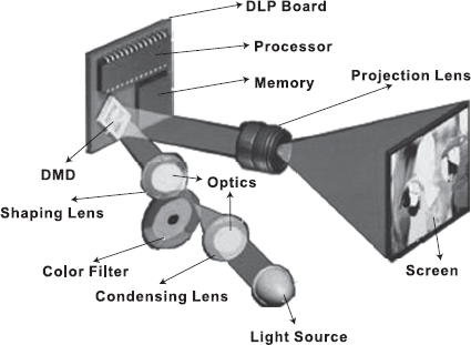
Figure 4.52 DLP Projector Display
4.3.7 Electronic Whiteboard
Electronic whiteboard is an interactive presentation device that works electronically to display digital images, drawings and text in different colours. The whiteboard is generally mounted on the wall and is connected to a computer (through USB, serial port or wireless technology like Bluetooth) and projector. The projector projects the computer's desktop on the whiteboard and user can interact with it using electromagnetic pens, fingers or other pointing devices (see Figure 4.53). The electromagnetic pens can be configured to any Figure 4.53 Electronic Whiteboard colour or width.
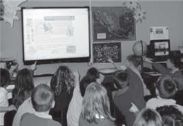
Figure 4.53 Electronic Whiteboard
A user can activate programs, applications and menus as well as enter text using either the on-screen keyboard or handwriting recognition utility. Nowadays, most whiteboards come with software that provides various tools and features to create virtual versions of paper flipcharts with pen, highlighter, etc., enhancing the use of electronic whiteboard to a great extent. Electronic whiteboard is widely used for various purposes such as to display presentations, for teaching in classrooms, in corporate meetings, professional sports coaching and so on.
An interactive electronic whiteboard can be classified into one of the following categories:
- Touch-based Whiteboard: A touch-based whiteboard allows user to use their fingers or other pointing devices to interact with it. The working on these whiteboards is easy as anything can be used as a pointer, for example, a stick, finger, etc., where the touch of a finger on the whiteboard is considered as a left click of the mouse.
- Pen-based Whiteboard: A pen-based whiteboard mainly uses an electromagnetic pen that alters electrical signals produced by the board and does not require batteries or power source for its operation. When the tip of the pen is pressed to the whiteboard, it results in the activation of a switch in the pen, which signifies a mouse click to the computer. These whiteboards are widely used by professional digital artists and designers as they help in providing more accurate information.
- Wii Remote, IR Pen-based Whiteboard: A Wii Remote, infrared (IR) pen-based whiteboard works on sound electronic and optical principles. It uses Wii remote control with IR camera placed in front of a remote control to track dots of an infrared light which is created by an IR pen. These whiteboards have become much popular due to their portability and reduced cost.
Note: The device driver software installed on the computer enables the whiteboard to act as a human input device (HID), just like a mouse, to help the user with easy interaction.
4.3.8 Headphone and Headset
Headphone is an audio device equipped with a pair of speakers attached to a headstrap worn by the users. Headphones are used with almost all electronic devices such as portable computers, CD/DVD players, mp3 players, iPod, etc. They comprise high-quality speakers, are light in weight and very comfortable to wear. They can be easily connected to a computer via a mini stereo plug.
The headphones allow the users to listen only; however, some applications like live chats, videoconferencing and telecalling services demand the user to also speak at the same time. For such applications, a headset is used instead of a headphone. A headset is a combination of one or two speakers and a Figure 4.54 Headphone and Headset microphone with both the speaker and the microphone attached to a headstrap. The speaker(s) allows the person to hear the conversation and the microphone allows the user to communicate with the person on the other end (see Figure 4.54).

Figure 4.54 Headphone and Headset
4.4 COMPUTER TERMINALS
A computer terminal is a special unit that can perform both input and output. A terminal is an I/O device that uses a keyboard for input and a monitor for output. Due to this reason, a terminal is also known as video display terminal (VDT ). Terminals can be categorized into the following types:
- Dumb Terminal: It refers to a terminal that has no processing or programming capabilities. It is designed to communicate exclusively with a host computer. Usually, it consists of a screen and keyboard used to access a host computer. It has electronics circuitry enough to interpret incoming instructions from the host computer, to display characters on the screen, to interpret keystrokes on the keyboard and pass them on to the host computer. Generally, dumb terminals are used for simple data entry or retrieval tasks. An example of a dumb terminal is one used by airline clerks at airport ticket and check-in counters.
- Smart Terminal: A smart terminal has built-in processing capability and memory but does not have its own storage capacity. In comparison to the dumb terminal, a smart terminal can communicate, retrieve data and can perform a limited processing of its own, that is, editing or verifcation of data. However, this kind of terminal cannot be used for programming. They are often found in local area networks in offices.
- Intelligent Terminal: An intelligent terminal has memory and inbuilt microprocessors, thus also known as user-programmable terminal. This terminal can independently perform a certain number of jobs without even interacting with the mainframe. Although they are intelligent terminals, some workstations are designed without disk drives. Due to this, restricted data cannot be downloaded or copied.
Let Us Summarize
- An input device is an electromechanical device that accepts data or information from the user and translates the information into a form which the computer can interpret.
- Keyboards are the most commonly used data entry devices. By pressing down the keys of the keyboard, data are entered into the computer.
- Pointing devices are the input devices by which we can point out and select items rapidly from the multiple options displayed on the screen. These devices can also be used to create graphic elements on the screen such as lines, curves and freehand shapes. The common types of pointing devices available are the mouse, trackball, joysticks, touch screens and light pens.
- Mouse is a small hand-held pointing device which can be used to input commands or information. It contains two or three buttons and by pressing one of the buttons, the mouse either marks a place on the screen or makes selections from the data on the screen. Common types of mouse action available are pointing, click, double-click, right-click and drag and drop.
- A trackball is an upturned mouse, with a movable ball on the top of a stationary base. It is used to control the cursor movements and the actions on a computer screen. It allows the user to perform each of these tasks separately.
- Joystick is a device that moves in all directions and controls the movement of the pointer. It activates the computer with different parts and is used to control the cursor on the screen.
- Using a light pen, one can select the objects on the monitor by directly pointing to the objects. It is useful for identifying a specific location. Since the light pen is a passive device with a sensor only, it provides no information when held over a blank part of the screen.
- A touch screen is a type of display screen device that is placed on the computer monitor in order to allow direct selection or activation of the computer when somebody touches the screen. It registers the input when a finger or other object touches the screen. It consists of three main components: a touch sensor, a controller and a software driver.
- Trackpad (also referred to as touchpad) is a stationary pointing device that works by sensing the movement of fingers across a small sensitive surface (1.5 or 2 inches) and translating them into the pointer movement on the screen.
- Speech recognition is the technology by which sounds, words or phrases spoken by humans are converted into digital signals, and these signals are transformed into coding patterns where the meaning has been assigned. It is more generally called as sound recognition.
- Digital camera records images in an electronic form, that is, the image is represented in computer's language of bits and bytes. It is a long string of 1s and 0s that represent all the tiny coloured dots or pixels that collectively make up the image.
- A webcam is a portable video camera, which captures live video or images that may be viewed in real time over the network or the Internet.
- A scanner is a device that scans an image and transforms the image to ASCII codes. These images can be edited, manipulated, combined and then printed. The common types of scanners are: handheld and flatbed.
- The optical character recognition (OCR) software translates the bitmap image of text to the ASCII codes that the computer can interpret as letters, numbers and special characters.
- The optical mark recognition (OMR) is the process of detecting the presence of intended marked responses. A mark registers significantly less light than the surrounding paper. Optical mark reading is done by a special device known as optical mark reader.
- A magnetic ink character reader (MICR) is used to recognize the magnetic ink characters; it reads the characters by examining their shapes in a matrix form.
- Bar codes are machine-readable codes, represented in parallel vertical lines with varying widths. By the combination of these vertical lines (bars) and the spacing between them, bar codes represent the alphanumeric data. For reading these bar-coded data, a device is used, which is known as a bar code reader.
- An output device is an electromechanical device, which converts machine-readable data or information into human-readable form. The printed form of output is referred to as hard copy while the form of output displayed on the screen is referred to as soft copy.
- Based on the hard copy and soft copy outputs, the output devices are classified into: hard copy and soft copy output devices. Printers, plotters and microfilms are the most commonly used hard copy output devices while monitors, voice response systems, projectors, electronic whiteboards, and headphones and headsets are some commonly used soft copy output devices.
- A printer is a device that prints information from the computer on to paper. The two major categories of printer technologies are impact printers and non-impact printers.
- An impact printer forms characters and graphics on a piece of paper by striking a mechanism against an ink ribbon that comes into physical contact with the paper. It includes dot matrix printers, daisy wheel printers and drum printers.
- Printers that form characters and images without making direct contact between printing mechanism and paper are called non-impact printers. They are categorized as ink-jet printers and laser printers.
- Hybrid document reproduction apparatus (HYDRA) printer, popularly known as all-in-one printer, is a device that consolidates the capabilities of multiple devices in one machine. It may include some or all of the devices like printer, scanner, photocopier and fax machine. Plotters are special-purpose drawing devices, which reproduce graphic images on paper using a pen whose movements are controlled by the computer. The lines drawn by these devices are continuous and very accurate. Plotters are classified as pen plotters and electrostatic plotters.
- Computer output microfilm is an extremely high-speed, low-cost process, which records computer-generated information directly from the computer tape or cartridge to a miniaturized microfilm media. The microfilm product is in fiche or roll format, which can be duplicated rapidly and inexpensively.
- Computer monitor is used to display the keyed data on the screen and to receive messages and processed information from the computer.
- Cathode ray tube (CRT) is the most common type of monitor for the office and the home. In a CRT, an electron gun is used which fires electrons at groups of phosphor dots coating the inside of the screen. When the electrons strike the phosphor dots, they glow to give the colours.
- In liquid crystal display (LCD) screen, the backlight passes through the first of two polarizing filters. The polarized light then passes through a layer that contains thousands of liquid crystal blobs aligned in tiny containers known as cells. Electric leads around the edge of the LCD create an electric field that twists the crystal molecule, which lines the light up with the second polarizing filter and allows it to pass through.
- Although CRT and LCD displays are the most commonly used, other kinds of displays also exist. Two of them are plasma display and thin-film electroluminescent display.
- The standard computer system can talk with the addition of two components: a speech synthesizer and a screen reading software. A speech synthesizer is a software that converts text information into spoken sentences. Screen reading software enables the user to control the synthesizer. It allows a user to access, or view text that is present on the screen.
- Screen image projector is an output device, which is used to project information from a computer on to a large screen, so that it can be simultaneously viewed by a large group of people. Projectors are mainly of two types: LCD projectors and DLP projectors.
- Electronic whiteboard is an interactive presentation device that works electronically to display digital images, drawings, and text in different colours. The whiteboard is generally mounted on the wall and is connected to a computer (through USB, serial port or wireless technology like Bluetooth) and projector.
- Headphone is an audio device equipped with a pair of speakers which are attached via a headstrap worn by the users. A headset is a combination of one or two speakers and a microphone with both the speakers and the microphone attached to a headstrap.
- Computer terminals, also called as display or video display terminals, enable a computer to receive or deliver data through input and output devices, respectively.
Exercises
Fill in the Blanks
- Mouse and light pen are examples of ............... input devices.
- Two basic methods used for optical character recognition (OCR) are ............... and
- ............... is a machine-readable code in the form of parallel vertical lines.
- MICR stands for ...............
- The bar-coded data represent the ............... and a device, which is used for reading the bar-coded data, is known as ...............
- The most used layout of a keyboard is ...............
- The printed form of output is referred to as ............... and the form of output, which is shown on a display screen, is referred to as...............
- An impact printer, which gives only alphanumeric output, is called...............
- ............... plotters are computer graphics devices that use drum or flatbed paper holder.
- A non-impact printer that forms an image by spraying ink from a matrix of tiny jets is called ...............
- The mouse may be classified as ............... or ...............
- ............... is the oldest printing technology.
- The quality of the monitor is generally judged by considering four basic terms ..............., ..............., ..............., and ...............
- The number of bits used to describe a pixel is known as ...............
- A computer can talk to persons through a device known as...............
Multiple-choice Questions
- ............... is the most commonly used input device.
- Keyboard
- Mouse
- Joystick
- Scanner
- Mouse, trackball and joystick are the examples of ...............
- Scanning devices
- Storing devices
- Pointing devices
- Multimedia devices
- Which of the following is not a computer terminal?
- Intelligent
- Smart
- Both (a) and (b)
- None of these
- Which of the following technique is best suited for bank cheques?
- OCR
- OMR
- BAR
- MICR
- Choose the most suitable device among the following for playing computer games.
- Hand-held scanner
- Joystick
- Optical Mark Reader
- Digital Camera
- Light pen is frequently used in ...............
- Computer Aided Design
- Word Processing
- Presentation
- Spreadsheet
- Choose the odd one out.
- QWERTY
- SULTRY
- AZERTY
- DVORAK
- Which of the following is not a pointing device?
- Scanner
- Trackball
- Light Pen
- Mouse
- Which of the following is not an output device?
- Printer
- Keyboard
- Monitor
- Plotter
- With the combinations of ..............., ............... and ............... colours, other colours can be shown.
- Red, Black, Blue
- Yellow, Blue, Green
- Red, Blue, Green
- Black, White, Yellow
- Which of the following is used for both input and output?
- Computer Terminals
- Pen Plotter
- Dot Matrix Printer
- None of these
- The ............... is also called as letter quality printer.
- Dot Matrix Printer
- Ink Jet Printer
- Daisy Wheel Printer
- Laser Printer
- The ............... terminal is referred to as non-programmable terminal whereas ............... terminal is referred to as user-programmable terminal.
- Dumb, Intelligent
- Dumb, Smart
- Smart, Intelligent
- None of these
- An individual small dot, which one sees on the computer screen is called ...............
- Font
- Character
- Screen Point
- Pixel
- LCD stands for ...............
- Liquid Colour Display
- Light Colour Display
- Lithium Crystal Display
- Liquid Crystal Display
State True or False
- Any hardware item that is attached to the CPU is referred to as peripheral device.
- Impact printers are slower as compared to non-impact printers.
- The speed of a printer is measured by character per minute.
- Audio response is a soft copy output.
- Dot pitch can be changed by the user.
- Plotters are best suited for desktop publishing.
- Bank cheques are an example of bar code marking.
- QWERTY is the most popular keyboard layout.
- A speech recognition system converts the computer text and commands into human spoken words.
- More pixels per square inch mean better resolution.
- A digital camera's photographs can be stored in a computer's hard disk.
- The most common aspect ratio used in computer monitors is 4:4.
- Raster scan monitors draw a picture one line at a time and for this reason they are referred to as vector displays, stroke-writing, or calligraphic displays.
- Ultrasonic acoustic waves are one of the most commonly used touch screen techniques.
- 16-bits colour allows up to 256 colours.
Descriptive Questions
- Why are input and output devices necessary for a computer system?
- What are pointing devices? Discuss some of the commonly used pointing devices.
- What is a touch screen device? Explain with their advantages and disadvantages and give some typical applications for which touch screen is most suitable as an input device.
- What is a speech recognition system? Explain its types and give logical reasons. Why do currently available speech recognition devices have limited success?
- What do you mean by optical scanning devices? Explain any four such devices.
- Explain the different types of printers. Make a clear difference between them in terms of speed, cost and method of operation, and suggest suitable applications.
- Describe the application areas where plotters are useful. Discuss the various types of plotters.
- What is speech synthesizer? How does it function? Give some of its typical applications.
- What is LCD? Differentiate between CRT and LCD monitors.
- Write short notes on the following:
- Resolution
- Aspect ratio
- Dot pitch
- Refresh rate
- Colour depth
ANSWERS
Fill in the Blanks
- Pointing
- Matrix matching, Feature extraction
- Bar code
- Magnetic ink character recognition
- Alphanumeric data, Bar code reader
- QWERTY
- Hard copy, Soft copy
- Daisy wheel
- Pen
- Ink-jet
- Mechanical mouse, Optical mouse
- Dot Matrix
- Size, Resolution, Refresh rate, Dot pitch
- Resolution
- Speech synthesizer
Multiple-choice Questions
- (a)
- (c)
- (c)
- (d)
- (b)
- (a)
- (b)
- (a)
- (b)
- (c)
- (a)
- (c)
- (a)
- (d)
- (d)
State True or False
- True
- True
- False
- True
- False
- False
- False
- True
- False
- True
- True
- False
- False
- True
- False