
We've handled outputs, but what makes robots truly interesting is the use of inputs to generate outputs! In this chapter, we'll go over basic input devices, such as buttons, and environmental sensors, such as a sensor that detects ambient light. We'll talk about how Johnny-Five uses events to make these devices easy to use, and build some projects. After finishing this chapter, you should have all the knowledge that you need to handle most input/output projects.
This chapter will cover the following topics:
- How analog input pins work
- Johnny-Five's sensor events
- Using basic inputs – buttons and potentiometers
- Using sensors – light and temperature
- Other types of sensors and their uses
For the project in this chapter, you'll need your board, a USB cable, and a few inputs and sensors.
First, you'll want a button. You can find these aplenty in most starter kits, but you can also buy them separately. We're going to consider a button with a four-prong design, as shown in the following screenshot:

A common push button for robotics projects
However, a design with two prongs is fine too—four-prong buttons still represent two sides of the button, so you can replicate these with two-prong designs.
You'll also need a rotating potentiometer—these are knobs that you twist to set a value, similar to the volume knob on a speaker. You'll want one that's breadboard-friendly with a three-prong design, as shown in the following screenshot:
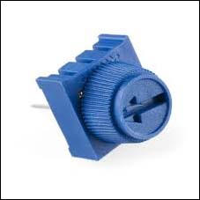
A basic rotating potentiometer
Tip
Please note that you may have access to a sliding potentiometer (one that looks like a sliding switch or similar to a dimmer switch) or some other potentiometer. These will work fine, but check the www.johnny-five.io site for more details on wiring them.
For inputs, first you'll need a light sensor that is commonly referred to as a photocell. Usually, these look like diodes that are tan with a wave design on top, as shown in the following screenshot:
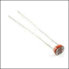
A light sensor diode
There are breakout boards for light sensors as well, but for this chapter, let's stick with the diode kind. These can be found very easily on Adafruit and SparkFun.
To round out our sensors, you'll want a temperature sensor. These look like small, half-cut cylinders with three metal prongs at the bottom. I recommend the TMP36, which has TMP written on the back, as shown in the following screenshot:

A temperature sensor
You can also use a LM35 with the same wiring—this sensor looks the same as the TMP36, except that LM35 is written on the back. If you use a different temperature sensor, before you continue, be sure to check the johnny-five.io documentation at http://johnny-five.io/api/temperature to see whether or not the sensor is supported.
You'll also need a breadboard, a handful of breadboard wires, an LED, and a few 10k Ohm resistors.
Resistors lower the electric current being sent to our sensors to ensure accurate readings and are also sometimes used to protect output devices. To make sure that your resistors are 10k ohm, we're going to use the colored stripes on the resistor. Your resistor should have brown, black, and orange bands. There may be another band after these—the color of this band, for our purposes, doesn't matter. The resistor should look like the following:
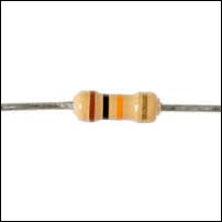
A 10k ohm resistor