
Having understood the basic laws of electronics, this section introduces you to the basic electronics components that are used in most of the electronics circuits.
A resistor is a passive two-terminal electrical component that resists the flow of electrons as a circuit element. The current through a resistor is in direct proportion to the voltage across the resistor's terminals. This relationship is represented by an alternative representation of Ohm's law, which yields the current I as the ratio of the potential difference V to the resistance R:
I= V/R
The symbol used for a resistor in a circuit diagram varies from standard to standard and one country to another:
In the real world, a typical axial lead carbon resistor will look like this:
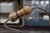
The value of the resistor can be measured by using the color code marked on them. The color bands of carbon resistors can be four, five, or six bands.
The first two bands represent the first two digits of resistance in ohms. The third band represents multiplier and the fourth band represents tolerance.
Values corresponding to a particular band can be found out using the following table:
|
Color |
First Two Digits |
Multiplier |
Tolerance |
|---|---|---|---|
|
Black |
0 |
100 |
- |
|
Brown |
1 |
101 |
± 1% |
|
Red |
2 |
102 |
± 2% |
|
Orange |
3 |
103 |
- |
|
Yellow |
4 |
104 |
- |
|
Green |
5 |
105 |
- |
|
Blue |
6 |
106 |
- |
|
Violet |
7 |
107 |
- |
|
Grey |
8 |
108 |
- |
|
White |
9 |
109 |
- |
|
Silver |
- |
10-2 |
± 10% |
|
Gold |
- |
10-1 |
± 5% |
Note
For example, the value of a four band carbon resistor having color bands Red, Green, Red, and Silver will be:
25*100=2500 ohms with 10% tolerance
So, in general, the value of carbon resistor will be (AB*C) Ohms with D tolerance, where A = the value corresponding to first band by referring to the "First Two Digits" column in the preceding table. In preceding example, the Red band corresponds to the value 2.
B = This is the value corresponding to the second band by referring to the "First Two Digits" column in the preceding table. In the preceding example, the Green band corresponds to 5.
C = This is the value corresponding to the third band by referring to the "Multiplier" column in the preceding table. In the preceding example, Red band corresponds to 100.
D= This is the value corresponding to the fourth band by referring to "Tolerance" columns in preceding table. In the preceding example, the Silver band corresponds to the value 10%.
In electrical circuits, it may happen that the exact value of resistor that is required might not be available, so sometimes, it is required to connect multiple resistors in series/parallel to get the required resistor value.
In a series configuration, the current through all of the resistors is the same, but the voltage across each resistor will be in proportion to its resistance. The potential difference (voltage) seen across the network is the sum of those voltages, thus the total resistance can be found as the sum of those resistances:
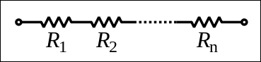
So, the equivalent resistor for the preceding case will be:
Req=R1+R2+...+Rn
Resistors in a parallel configuration are at the same potential difference (voltage); however, the currents through them get added at junction and can be of different value based on resistor value. The conductance (inverse of resistance) of the resistors then add to determine the conductance of the network:
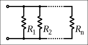
So, the equivalent resistor for the preceding case will be:
1/Req=1/R1+1/R2+....+1/Rn
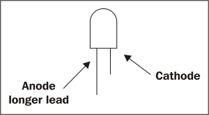
The resistor will block the flow of current in both directions. A diode is a two-terminal electronics component that has low resistance in one direction and high resistance in other direction. Diodes are mostly made up of silicon. The commonly used symbol for a diode is shown in the common electronics components table. LEDs are the most commonly used diodes in any electronics circuit. LED stands for Light Emitting Diode, so it emits light and sufficient voltage is provided across the LED anode and cathode. The longer lead of the LED is anode and the other end is cathode. The color of the light depends on the semiconductor material used in the LED, as shown in the following diagram:
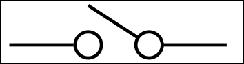
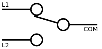
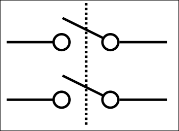
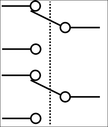
A switch is a component that interrupts the flow of current or diverts it from one conductor to another. There are few concepts such as debounce, interrupts, and polling that you need to know for better understanding of certain things. In mechanical switches, when the two contacts strikes, their momentum and elasticity act together to cause them to bounce apart one or more times before making a steady contact. In sensitive analog circuits, this will cause misinterpretation of the ON-OFF pulse and may lead to undesirable behavior of the circuits. To avoid this, debouncing circuits are used.
In order to understand debouncing circuits however, you first need to understand the concepts of interrupts and polling:
- Polling means constantly looking for something. This can be applied in software to any user interface where the microcontroller can poll the I/O pins to check whether there are any user inputs.
- On the other hand, interrupts use hardware to implement a more efficient way to know the controller that user inputs or a certain event has occurred. For example, your software scripts will constantly look for the certain I/O pin to check a user input is received or not, while on the other hand, when you insert the USB keyboard to Raspberry Pi, it will generate the interrupt and notify the firmware, which in turn stops the current processing task and load the keyboard driver (or actions related to that interrupt). Once this is completed, it will resume the last processing task. The following table has information about commonly used switches:
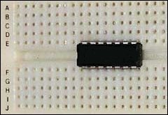
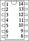
Integrated circuits, commonly referred to as IC, are electronics components that combine several electronics components to a perform-specific task. For example, to control the motor, you require a higher current signal than that of your circuit can provide. In this case, you need to create another circuit that amplifies the current to a certain level that it can drive the motors and that will be a lot of effort. Instead of that, you can use L293D motor driver IC, which does the same thing. You can get more information (such as which pin does what task, what input it takes, what output it can provide, and so on) about a particular IC by reading its datasheets. Don't worry if at this moment it does not make that much sense, you will understand this better in the later part of this chapter. Integrated circuits come in different packaging. Typically the Dual In-Line Package (DIC) IC symbol is used, which is shown in the Common Electronics Components table.
In electronics term, a sensor is a device that measures the quantity in the physical world and converts it into a format that is readable by an electronic instrument. The touchscreen of a mobile will be the best example of sensor that takes the input in the physical world from a user and converts it into a format that will be understood by the processor. A sensor's sensitivity indicates how much the sensor's output changes when the measured physical world quantity changes.
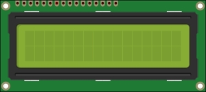
As you know, LCD stands for liquid crystal display. However, in electronics, you will be using a different LCD. In the later part of this chapter, you will be using 16*2 characters LCD JHD162A. 16*2 means in the JHD162A LCD, there will be 16 columns and 2 rows, which can be used to display 32 characters on the screen.
For connecting different electronics components in the prototype circuits, you will require connecting wire or hook up wire (you will see different terminology used at different places). This can be of two types: single-threaded and multi-threaded. From personal experience, I found it easy to work with a single-threaded wire than that of a multi-threaded wire.
Often you will require to test the prototype of the circuits that you have developed. Breadboard serves as a construction base for testing the electronics prototype. On breadboard, you can test your prototype without doing any kind of soldering just by connecting different components using wires. Have a look at this image to know how breadboard looks in the real world:
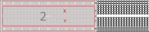
You will see two different sections (or areas called strips) in the breadboard:
- Terminal strips: This is the main area of the breadboard, which is generally used to hold most of the electronic components; this area is marked as area 2. As you can see in the following diagram, in this area, all the column are interconnected. The interesting part is that there is some space that divides this area into two subareas X and Y. This space is specifically designed for inserting Integrated circuits (IC) on the breadboard. So, when IC is plugged into a breadboard, the pins of one side will go to E, while the other side of pins will go to the F part:
- Bus strips: The main use of a bus strip, which is marked as area 1a and 1b, is to provide power supply to the electronic components that are plugged-in on the terminal strips. Typically, there are two rows: one for ground and another one for a supply voltage. The first row is used to provide supply voltage and the second one to provide ground. A similar structure is available at the bottom of the breadboard to provide power supply and ground to the bottom part of the breadboard electronics component, where providing power supply and ground from the top part would be difficult in some cases.
A full-size terminal breadboard typically consists of around 56 to 65 columns of terminal strips, each column containing the two sets of connected clips (A to E and F to J), as mentioned earlier. Together with bus strips on each side, this makes up a typical 784 to 910 tie point/holes.
There are other electronics components that will be used in this book, but for now, the preceding information will help you get started. Other electronics components will get introduced to you as and when it is used.
Here's a table that shows you the common electronics components:

Before this chapter, you have used Raspberry Pi as a web server, developed games, and created OS for it, but till this point, you haven't interacted much with the other parts of the development board. This section will take you on a tour of important electronics components/interfaces that will be used in this book.
There are four electronics components on Raspberry Pi that you need to understand, namely P1, P2, P3, S2, and S5:
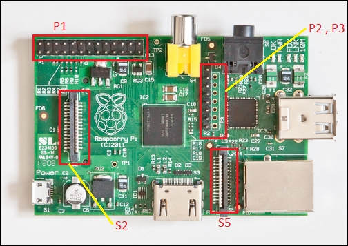
P1: This is commonly referred to as the GPIO connector. The GPIO connector actually has a number of different types of connections on them. They are:
- True General-purpose input/output (GPIO) pins that you can use to turn LEDs on and off and so on.
- Inter-Integrated Circuits (I2C) interface pins that allow you to connect low-speed hardware modules with just two control pins
- Serial Peripheral Interface (SPI), which is an interface with SPI devices, a similar concept to I2C but a different standard
- Serial Rx and Tx pins for communication with serial peripherals
In the following image, Raspberry Pi pin numbers are shown. However, the Broadcom (the processor that is being used in Raspberry Pi) GPIO pin numbers are different than what is shown in the preceding image. So, mapping of pins as well as their functionality is displayed in the following table:
|
Broadcom chip numbers and functionality |
Pin number |
Pin number |
Broadcom chip numbers and functionality |
|---|---|---|---|
|
3.3 V |
1 |
2 |
5 V |
|
GPIO 0 (SDA) : (Rev. 2) GPIO 2 |
3 |
4 |
5 V |
|
GPIO 1 (SLA) : (Rev. 2) GPIO 3 |
5 |
6 |
GND |
|
GPIO 4 |
7 |
8 |
GPIO 14(TXD) |
|
GND |
9 |
10 |
GPIO 15(RXD) |
|
GPIO 17 |
11 |
12 |
GPIO 18 |
|
GPIO 21 : (Rev. 2) GPIO 27 |
13 |
14 |
GND |
|
GPIO 22 |
15 |
16 |
GPIO 23 |
|
3.3 V |
17 |
18 |
GPIO 24 |
|
GPIO 10 (MOSI) |
19 |
20 |
GND |
|
GPIO 9 (MISO) |
21 |
22 |
GPIO 25 |
|
GPIO 11 (SCKL) |
23 |
24 |
GPIO 8 |
|
GND |
25 |
26 |
GPIO 7 |
As you can see in the previous table, you can use Pin 3 and Pin 5 for I2C, Pin 19, Pin 21, and Pin 23 for SPI to connect to SPI devices and Pin 8 and Pin 10 for UART communication. Right now, you don't have to worry about I2C, SPI, and UART; just bookmark this page, as it will be required when you want to program/control the device that is connected to one of this GPIO ports. For example, to change Pin 16 of the GPIO to HIGH, you have to use GPIO 23 to do the same.
P2 & P3: The P2 header is the VideoCore JTAG and used only during the production of the board. This cannot be used as the ARM JTAG. This connector is unpopulated in revision 2.0 boards. The P3 header, unpopulated, is the LAN9512 JTAG.
Some useful P2 and P3 pins are as follows:
|
Useful P2 pins |
Useful P3 pins |
|---|---|
|
Pin 1 - 3.3 V |
Pin 7 - GND |
|
Pin 7 – GND |
- |
|
Pin 8 – GND |
- |
S2 & S5: S2, the display serial interface, or DSI, is a high speed serial connector located between the power connector and the GPIO header on Raspberry Pi. The purpose of the DSI connector is to give the end user a quick and easy way to connect an LCD panel to the Pi. However, mostly, the HDMI port is used to connect with an LCD. S5 is the camera serial interface that can be used for connecting camera devices with Raspberry Pi. In 2013, a compatible 5 Megapixels and 1080p video resolutions camera was launched by Raspberry Pi.
As discussed in the earlier section, Raspberry Pi has 26 GPIO pins. These pins can be accessed/programmed using the WiringPi library, which is written in C for the BCM2835 processor used in Raspberry Pi. This is usable from C, C++, and many other languages using a suitable wrapper. In this book, the WiringPi Python wrapper is used.