
Having understood the important electronic components in this section, you will develop a remote controlled robot with live camera feed and live distance to the nearest wall. Similar to the previous chapter, in this chapter, you will develop a couple of small projects and then combine all of them to make a larger project. You can develop three small projects and then merge it to make a larger project:
- Calculating distance using an ultrasonic sensor
- Displaying a live feed from the Raspberry Pi camera module
- Developing a remote-controlled robot using the Raspberry Pi
Before you go ahead make sure you have all the components listed here:
- Raspberry Pi
- Raspberry Pi power supply
- The HC-SR04 ultrasonic sensor
- Hook up wires
- 330 Ohm resistor
- 470 Ohm resistor
Only Python and the Raspberry Pi GPIO library are required to be installed on Raspberry Pi, which you will install in Chapter 5, Introduction to Image Processing, so no additional setup is required.
As mentioned in the ultrasonic sensor introduction section, powering up the module is easy. First, you need to connect the GND pin to the Raspberry Pi GND Pin, that is, Pin 6. Once you have connected the GND pin, connect the Vcc pin to Pin 2 of Raspberry Pi, which can provide 5V DC. The input pin on the module is called the Trig, which is used to trigger the sending of the ultrasonic pulse. Ideally, it wants a 5V pulse, but it works fine with a 3.3 V signal provided from Raspberry Pi GPIO pins. Connect Trig to Pin 24 of the Raspberry Pi. The output pin on the module is called Echo. The output pin remains low (0V) when the module has taken the distance measurement. This sets the Echo pin HIGH (5V) for the amount of time that it took to return the pulse. This module uses +5V as HIGH, but it is too HIGH for Raspberry Pi GPIO as it operates in 3.3 V. If you give +5V to the Raspberry Pi GPIO, it might affect the normal functionality of Raspberry Pi, so to avoid this situation, you can use a level converter, which was introduced in the previous section. However, here you can create a basic voltage divider circuit using two resistors.
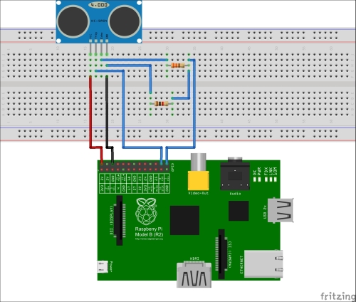
Here is the complete connection diagram. In this circuit, Raspberry Pi Pin 24 and Pin 26 are used for Trigger and Echo respectively. You can use any other GPIO pins of the Raspberry Pi, and you can update the script accordingly.
Once you have connected ultrasonic sensor pins with Raspberry Pi as per the diagram, boot up your Raspberry Pi.
Create a new python script by right-clicking on Create | New File | Ultrasonic.py.
Here is the code that needs to be copied in the file Ultrasonic.py:
#Setup Start

import time
import RPi.GPIO as GPIO

GPIO.setmode(GPIO.BCM)

GPIO_TRIGGER = 8
GPIO_ECHO = 7

GPIO.setup(GPIO_TRIGGER,GPIO.OUT)  # Trigger
GPIO.setup(GPIO_ECHO,GPIO.IN)      # Echo

# Set trigger to False (Low)
GPIO.output(GPIO_TRIGGER, False)

# Allow module to settle
time.sleep(0.5)

#SetUp Ends

#Processing Start
# Send 10us pulse to trigger
GPIO.output(GPIO_TRIGGER, True)
time.sleep(0.00001)
GPIO.output(GPIO_TRIGGER, False)

start = time.time()
while GPIO.input(GPIO_ECHO)==0:
  start = time.time()

while GPIO.input(GPIO_ECHO)==1:
  stop = time.time()

# Calculate pulse length
elapsed = stop-start
distance = elapsed * 34000
distance = distance / 2

print "Ultrasonic Measurement Distance : %.1f" % distance

# Reset GPIO settings
GPIO.cleanup()

#Processing Ends
Run the Python script by executing the following line in your terminal:
sudo python Ultrasonic.py
You will see the distance of the nearest wall in centimeters in the output. First step is to get the necessary library:
import time
import RPi.GPIO as GPIO
It will import the required Python library. In this case, only time and the GPIO library is required.
GPIO.setmode(GPIO.BCM)
This uses GPIO.BCM references instead of physical pin numbers. Throughout this book, you will be using the BCM.GPIO reference to maintain the consistency.
GPIO_TRIGGER = 8
GPIO_ECHO = 7
The preceding lines defines the GPIO port number, which will be used for Trigger and Echo. As mentioned earlier, Pin 24 (BCM.GPIO Pin number 8) and Pin 26 (BCM.GPIO Pin number 7) will be used for Trigger and Echo respectively.
GPIO.setup(GPIO_TRIGGER,GPIO.OUT)  # Trigger
GPIO.setup(GPIO_ECHO,GPIO.IN)      # Echo
This will set up the GPIO port of Raspberry Pi as OUT and IN. It will set the GPIO Trigger pin as OUTPUT as you will be sending the Trigger signal to the ultrasonic module. Similarly, it will set the GPIO Echo pin as INPUT as you will get the response from the ultrasonic module once you have sent the Trigger pulse to the module. To send a trigger, first you need to setup the Trigger pin to FALSE to avoid sending any unwanted pulse:
GPIO.output(GPIO_TRIGGER, False)
   time.sleep(0.5)
It will set Trigger to False (Low), and after this, it will wait for 0.5 seconds, which will give enough time to the module to settle.
GPIO.output(GPIO_TRIGGER, True)
time.sleep(0.00001)
GPIO.output(GPIO_TRIGGER, False)
As mentioned in the ultrasonic sensor module section, first you need to send the 10 µs Trigger pulse to the Trigger pin, and then the module will send the output to the Echo pin. Next step is to measure the time that is taken by sound waves to bounce back:
start = time.time()
while GPIO.input(GPIO_ECHO)==0:
  start = time.time()

while GPIO.input(GPIO_ECHO)==1:
  stop = time.time()
Once you have sent the Trigger pulse, as explained in the ultrasonic sensor module section, after some time, you will receive the reflected sound waves. You need to calculate the time that is taken by sound waves to bounce back.
elapsed = stop-start
distance = elapsed * 34000
distance = distance / 2
Calculate the pulse length by finding the time difference between start and stop. The distance pulse travelled in that time is time multiplied by the speed of sound (cm/s), that is, 34000 cm/s. This is the total distance that is covered by the sound waves. To calculate the distance to the nearest wall, you need to divide it by 2.
print "Ultrasonic Measurement Distance : %.1f" % distance
GPIO.cleanup()
It will print the distance on the screen, and after this, it will reset the GPIO pin settings.
In this section, you will develop a project in which you can see the live feed from the camera module in the browser. Before you start working on this project, make sure you have the following components with you:
- Raspberry Pi
- The Raspberry Pi camera module
- Internet connectivity on Raspberry Pi
In this project, you will live stream from the Raspberry Pi camera, and for live streaming, you will need a web server installed on your Raspberry Pi. For this, you will be using Apache web server with PHP support. For live streaming of the video from the Raspberry Pi camera module, you will use the MJPG-streamer library. Before you start using MJPEG-library, there is a dependency library that needs to be installed. In your terminal, execute this to install the dependency library and Apache server with PHP support:
sudo apt-get install libv4l-dev libjpeg8-dev subversion imagemagick libapache2-mod-php5 php5 apache2
Once you have all the dependency installed, check out the MJPEG-streamer repo by typing the following command in terminal:
svn co https://svn.code.sf.net/p/mjpg-streamer/code/ MJPG-streamer
Once this gets completed, you will get the MJPEG-streamer folder. You have checked out the MJPEG-streamer source files to your Raspberry Pi. Now, you need to build it so that you can use it. Run the following command in your terminal to create the necessary executables:
cd MJPG-streamer/mjpg-streamer
sudo make USE_LIBV4L2=true
This will generate some executable and shared libraries in this folder. This folder should contain the following files:
mjpg_streamer(binary)input_uvc.soinput_file.sooutput_http.so
Cross-check by opening the MJPG-streamer/mjpg-streamer folder.
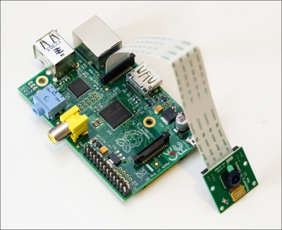
The Raspberry Pi camera module can be used to take full HD 1080p photos as well as video. This can also be controlled programmatically. You already saw a couple of examples in The Raspberry Pi camera section. The camera may come with a small piece of translucent blue plastic film covering the lens. It is there just to protect the lens while it is getting shipped to you. Once you have received it, you may remove it by gently peeling it off.
The camera module that you bought has also come with the flex cable. This flex cable should be connected to the connector S5 situated between the Ethernet and HDMI ports. This connector should be opened by pulling the tabs on top of the connector, upwards then towards the Ethernet port. The flex cable should be inserted firmly into the connector, with care taken not to bend the flex at too acute an angle. The top part of the connector should then be pushed towards the HDMI connector and down, while the flex cable is held in place.
The streaming server needs a sequence of JPEG files to stream, and for this, you will use the raspistill utility that is part of Raspbian to which you are already familiar with. The raspistill utility uses the JPEG encoder, which will run in the GPU, so the load required to generate the JPEG is much less and it does not have a major effect on the performance of Raspberry Pi:
- First, you need to create a directory where the JPEG stream will get created. Run the following command in the terminal window:
mkdir /home/pi/stream - Once you have created the directory, run the following command in the terminal to create a continuous stream of images:
raspistill -w 640 -h 480 -q 5 -o /home/pi/stream/pic.jpg -tl 100 -t 9999999 -th 0:0:0 -n &-wsets the image width. For an HD stream use 1920 here.-hsets the image height. For an HD stream use 1080 here.-qsets the JPEG quality level, from 0 to 100. Here it is a pretty low quality that is 5, better quality generates bigger pictures, which reduces the frame rate.-osets the output filename for the JPEG pictures. You will send them to a /home/pi/stream directory. The same file will be rewritten with updated pictures.-tlsets the timelapse interval, in milliseconds. With a value of 100 you get 10 frames per second.-tsets the time the program will run. You need to put a large number here, that amounts to about two hours of run time.-thsets the thumbnail picture options. Since I want the pictures to be as small as possible I disabled the thumbnails by setting everything to zero.-n, Do not display a preview window&puts the application to run in the background.So now you have the background task, that is, writing JPEG from camera at a rate of 10 per second.
- The only thing that is left is to start a streaming server. Run the following command in your command line to start the streaming server:
LD_LIBRARY_PATH=/home/pi/MJPG-streamer/mjpg-streamer/ /home/pi/MJPG-streamer/mjpg-streamer/mjpg_streamer -i "/home/pi/MJPG-streamer/mjpg-streamer/input_file.so -f /home/pi/stream -n pic.jpg" -o "/home/pi/MJPG- streamer/mjpg-streamer/output_http.so -p 8081 -w /home/pi/MJPG-streamer/mjpg-streamer/www" &LD_LIBRARY_PATHsets the path for dynamic link libraries to the current directory. This is so that the application can find the plugins, which are in the same directory.-isetsthe input plugin. You need to use a plugin called input_file.so. This plugin watches a directory and any time it detects a JPEG file was written to it it streams that file.-fsets the folder to watch for MJPEG stream-osets the output plugin. You will use the HTTP streaming plugin, which starts a web server that you can connect to to watch the video.-psets the port number on which you can watch the video-wsets the root directory of the web server. You will use the default web pages that come with the application for now, these can be changed and customized as necessary.&puts the application to run in the background. - Now, you have everything ready. You can check the live stream from the Raspberry Pi camera module on any device that has a web browser and is connected to the same network as Raspberry Pi. Open the browser and connect to the following website:
http://<IP-ADDRESS>:8081Here, IP-ADDRESS is the IP address of the Raspberry Pi where the web server is hosted.
The default website served by the streaming server provides access to several players to watch the stream. Go to the Stream section, where you will be able to see the live stream. For now, you can use this default page, but in the later part of this chapter, you will create an HTML/PHP page where you can include this stream.
In this section, you will develop a remote-controlled robot. Before you get started, make sure you have the following components with you:
- Raspberry Pi
- 4 wheels
- 4 DC motors of 200 RPM
- Hook-Up wires
- Robotic base
- L293D motor driver IC
- Power bank (Todo: Add the details of power bank that you have used)
Python and Raspberry Pi GPIO libraries are required to be installed on Raspberry Pi, which you have already installed in Chapter 5, Introduction to Image Processing. For controlling the robot remotely, you need to install the web server on the Raspberry Pi, which you already did in the previous section.
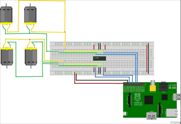
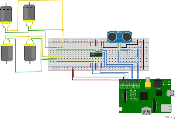
Once you have all the component handy with you, and after you have set up the Raspberry Pi, you will require motor driver IC L293D to control the motors. First, you need to connect the motors to the robotic base. Once this is done, you can connect the Raspberry Pi and motor driver IC and DC motors; as per the following diagram you can do the connection in two steps. First, connect the motors with the motor driver IC, and then connect the motor driver IC with Raspberry Pi GPIO pins.
As mentioned earlier in the section of Motor driver IC, a single L293D can simultaneously control two motors. In the current case, where you are using four DC motors, you will require to have two L293D IC; however, for simplicity in the following diagram, two motors are connected in parallel to each side of the single L293D IC.
Once you have connected the Raspberry Pi pins with the L293D pins, you can start scripting for controlling the GPIO ports of Raspberry Pi using the web server. For this, you need to add www-data to sudoers because for accessing GPIO ports of the Raspberry Pi, you require sudo (super user) permissions:
sudo echo "www-data ALL=(ALL) NOPASSWD: ALL" >> /etc/sudoers
The preceding command will add www-data (the web server files) to the sudo user group, which can access the GPIO ports of the Raspberry Pi without any password.
To control the Raspberry Pi GPIO remotely, you will need a user interface, which the user can use to send the command to the web server, and then the web server will send the command to control the GPIO of the Raspberry Pi.
- Execute the following command in your terminal to create a folder specific to this project:
mkdir /home/pi/remoteRobot - Close the terminal and create a new file by right-clicking on Create | File |
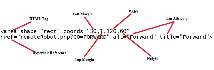
remoteRobot.html. Paste the following code in the file:<html> <head> <meta http-equiv="Content-Type" content="text/html; charset=UTF-8"> <title>Raspberry Pi remote Controlled Robot</title> </head> <body> <center> <div id="controls"> <a href="remoteRobot.php?GO=ON">Connect to Engine</a><br/> <img src="controller.png" usemap="#controls" /><br /> </div> <map name="controls"> <area shape="rect" coords="30,1,120,60"href="remoteRobot.php?GO=FORWARD" alt="Forward" title="Forward"> <area shape="rect" coords="1,60,70,120"href="remoteRobot.php?GO=LEFT" alt="Left" title="Left"> <area shape="rect" coords="30,130,120,180"href="remoteRobot.php?GO=BACKWARD" alt="Backward" title="Backward"> <area shape="rect" coords="130,60,180,120"href="remoteRobot.php?GO=RIGHT" alt="Right" title="Right"> </map> </center> </body> </html>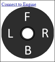
You have already learned HTML and related concepts in Chapter 2, Developing Web Applications. In the user interface, you will require START, FORWARD, BACKWARD, LEFT, and RIGHT functionality/controls. Line 1 to Line 7 should be self-explanatory. Line 9 to Line 12 defines the controls. Initially, for connecting the Robot, Line 10 will create an hyperlink with
remoteRobot.php?GO=ONas the hyperlink reference. You will create aremoteRobot.phpfile in the next subsection, which will control the GPIO of the Raspberry Pi based on the command received from the user interface page. Line 11 defines the image for other four controls FORWARD, BACKWARD, LEFT, and RIGHT. Now, to attach events to different parts of the image, a map is used. Theusemapattribute specifies an image as a client-side image-map (an image-map is an image with clickable areas). Theusemapattribute is associated with a<map>element's name or ID attribute, and creates a relationship between the<img>and<map>tags. Line 13 to Line 18 maps the area of an image to four clickable areas:<area shape="rect" coords="30,1,120,60"href="remoteRobot.php?GO=FORWARD" alt="Forward" title="Forward"> coords - Left Margin, Top Margin , Width , Height href - hyperlink reference
- The remaining lines of the code should be self-explanatory.
As mentioned in the Creating a user interface for controlling the robot section, you need to perform total of five functionalities:
- Initialization
- Forward Movement
- Backward Movement
- Left Movement
- Right Movement
You cannot directly access the Raspberry Pi GPIO pins. First, you need to export the GPIO pins that you want to use, and then set it as either out or in based on the requirement. When you want to use the GPIO pin as an output, set it as out. Similarly, if you want to use it as input pin, set it as in. In this section, you will be using 4 GPIO (14,18,24,23) pins and the output of these GPIO pins are used to control the motors, so you need to set all four GPIO ports as out.
Go to the /home/pi/remoteRobot folder and right-click on Create | New File | init.sh:
Copy the following code into the file:
echo "14" > /sys/class/gpio/export
echo "18" > /sys/class/gpio/export
echo "24" > /sys/class/gpio/export
echo "23" > /sys/class/gpio/export
echo "out" > /sys/class/gpio/gpio14/direction
echo "out" > /sys/class/gpio/gpio18/direction
echo "out" > /sys/class/gpio/gpio23/direction
echo "out" > /sys/class/gpio/gpio24/direction
As per the connection diagram in the Connecting Raspberry Pi pins and robot section, it is clear that you need to set GPIO 14 and GPIO 24 to HIGH for FORWARD movement of the robot. Here is the complete table depicting all the movements and related GPIO pins value:
|
GPIO 14 |
GPIO 18 |
GPIO 24 |
GPIO 23 | |
|---|---|---|---|---|
|
Forward |
HIGH |
LOW |
HIGH |
LOW |
|
Backward |
LOW |
HIGH |
LOW |
HIGH |
|
Left |
LOW |
HIGH |
HIGH |
LOW |
|
Right |
HIGH |
LOW |
LOW |
HIGH |
Go to the /home/pi/remoteRobot folder and right click on Create | New File | forward.sh.
Copy the following code into the file:
echo "1" > /sys/class/gpio/gpio14/value
echo "0" > /sys/class/gpio/gpio18/value
echo "1" > /sys/class/gpio/gpio24/value
echo "0" > /sys/class/gpio/gpio23/value
sleep 1
echo "0" > /sys/class/gpio/gpio14/value
echo "0" > /sys/class/gpio/gpio18/value
echo "0" > /sys/class/gpio/gpio24/value
echo "0" > /sys/class/gpio/gpio23/value
The first four lines set the GPIO pins as per the preceding table are for the forward movement. After 1 second (sleep 1), all four GPIO pins should be set to LOW; otherwise, the robot will keep on moving in the forward direction.
Similar to forward movement, all three movements can be configured. Here is the code for the remaining three files:
Go to /home/pi/remoteRobot folder and right-click on Create | New File | backward.sh.
Copy the following code into the file:
echo "0" > /sys/class/gpio/gpio14/value
echo "1" > /sys/class/gpio/gpio18/value
echo "0" > /sys/class/gpio/gpio24/value
echo "1" > /sys/class/gpio/gpio23/value
sleep 1
echo "0" > /sys/class/gpio/gpio14/value
echo "0" > /sys/class/gpio/gpio18/value
echo "0" > /sys/class/gpio/gpio24/value
echo "0" > /sys/class/gpio/gpio23/value
Go to the /home/pi/remoteRobot folder and right-click on Create | New File | left.sh.
Copy the following code into the file:
echo "0" > /sys/class/gpio/gpio14/value
echo "1" > /sys/class/gpio/gpio18/value
echo "1" > /sys/class/gpio/gpio24/value
echo "0" > /sys/class/gpio/gpio23/value
sleep 1
echo "0" > /sys/class/gpio/gpio14/value
echo "0" > /sys/class/gpio/gpio18/value
echo "0" > /sys/class/gpio/gpio24/value
echo "0" > /sys/class/gpio/gpio23/value
Go to the /home/pi/remoteRobot folder and right-click on Create | New File | right.sh.
Copy the following code into the file:
echo "1" > /sys/class/gpio/gpio14/value
echo "0" > /sys/class/gpio/gpio18/value
echo "0" > /sys/class/gpio/gpio24/value
echo "1" > /sys/class/gpio/gpio23/value
sleep 1
echo "0" > /sys/class/gpio/gpio14/value
echo "0" > /sys/class/gpio/gpio18/value
echo "0" > /sys/class/gpio/gpio24/value
echo "0" > /sys/class/gpio/gpio23/value
Now, you need to move this control script to the webserver folder as you want to control GPIO from there. Open your terminal and execute the following command to copy these files to the /var/www/ folder:
cd /home/pi/remoteRobot/
sudo cp init.sh forward.sh backward.sh left.sh right.sh /var/www/
You have already defined commands in the user interface page (remoteRobot.html) that should be sent to the PHP page. Here is the complete list:
|
Command |
Action |
Script |
|---|---|---|
|
On |
This connects to the robot or Initialize the robot |
|
|
Forward |
Forward movement |
|
|
Backward |
Backward movement |
|
|
Left |
Left Turn |
|
|
Right |
Right Turn |
|
You have also written a script, which can control the GPIO from webserver folder. Now, what is left is to call the particular script based on the command received from the user interface page. The preceding table contains the mapping of the command and script that needs to be called.
Go to the /home/pi/remoteRobot folder and right-click on Create | New File | remoteRobot.php
Copy the following code into the file:
<?php
session_start();
include "remoteRobot.html";
$action = $_GET['GO'];
switch ($action)
{
  case "ON":
    shell_exec('sudo /bin/bash /var/www/init.sh'),
    break;
  case "FORWARD":
    shell_exec('sudo /bin/bash /var/www/forward.sh'),
    break;
  case "BACKWARD":
    shell_exec('sudo /bin/bash /var/www/backward.sh'),
    break;
  case "LEFT":
    shell_exec('sudo /bin/bash /var/www/left.sh'),
    break;
  case "RIGHT":
    shell_exec('sudo /bin/bash /var/www/right.sh'),
    break;
}
?>
Line 1 will be used to tell the browser that it is a PHP file and needs to be executed on server. Line 2 will start a new session. Line 3 will include the HTML page that you have created before in this section. Line 4 will store the value for the key GO that has been sent to the PHP page by an user interface page. Once you have received the value of the command, based on the value as per the preceding table, you need to call execute a particular shell script. For example, in the case of ON, a command line 8 will execute the init.sh script. shell_exec is the PHP which can be used to run the shell script from the command line.
You have already copied the control script to the /var/www/ folder so that it can be accessed in the server. Now, you need to move the user interface page and the corresponding server page to the /var/www/ folder so that it can be accessed from anywhere in the same network. Open your terminal and execute the following script to move the remoteRobot.html and remoteRobot.php file to the /var/www/ folder:
cd /home/pi/remoteRobot/
sudo cp remoteRobot.html remoteRobot.php /var/www/
Now, you can control your robot from any machine that is connected to the same network using just a browser. Open the browser and type the following command to control your robot:
http://<IP-Address>/remoteRobot.php
where IP-Address - IP Address of Raspberry Pi
First, you have to click on Connect the Robot. Once robot is connected, you can use the button displayed on the screen to control the robot.
You have developed all the three projects. In this section, you will merge everything to make a large project that is a remote-controlled robot with live streaming and live distance measurement. From the development of the three projects, it is clear that you need to extend the Developing a remote-controlled robot using Raspberry Pi section. Before moving ahead, make sure you have all the components mentioned in all the three projects.
Do not disconnect the connection that you have done in the previous section of Developing a remote-controlled robot using Raspberry Pi. In addition to this, you have to connect the Raspberry Pi camera module to the CSI connector as mentioned in the Displaying live feed from the Raspberry Pi camera module section. Once you have connected the Raspberry Pi camera, connect the ultrasonic sensor as per the connection diagram mentioned in Calculating distance using an ultrasonic sensor section. Once you have connected everything, make sure your connection matches with the connection diagram displayed in the following figure:
From the development of all three projects, it is clear that to merge everything the following files needs to be updated:
remoteRobot.html: User interface needs to be created for displaying live stream as well as live distance measurement.init.sh: There are some initial commands that need to be executed before you can see the live stream. These commands needs to be included in this file/var/www/: Copyultrasonic.pyfile to this folder so that it can be. executed from the web server
You need to display the live stream and live ultrasonic measurement distance, for this create two <div> tags as follows:
  <div id="streamdata" style="float: left;">
<img src="http://<IP-address>:8081/?action=stream"/>
  </div>
The preceding code will display live stream in an image. The image source has been given as http://<IP-address>:8081/?action=stream, which is used to get the live stream from the port number 8081. Next step is to create placeholder where distance measured by ultrasonic sensor will get displayed:
  <div id="distance">Ultrasonic Measurement Distance
  </div>
In the previous code, Ultrasonic Measurement Distance will get displayed, but currently the script that you have run for a single time does not provide live data. For this, you need to create a script, which will automatically call the ultrasonic python script every one second:
<script type="text/javascript">
setInterval(function(){
if(XMLHttpRequest) var x = new XMLHttpRequest();
elsevar x = new ActiveXObject("Microsoft.XMLHTTP");
x.open("GET", "ultrasonic.php", true);
x.send();
x.onreadystatechange = function(){
if(x.readyState == 4){
if(x.status == 200) document.getElementById("distance").innerHTML = x.responseText;
else document.getElementById("distance").innerHTML = "Error loading document";
        }
    }
},5000);
</script>
You can call the PHP file from the HTML file by making a GET request by assuming you already know what the GET request is. Line 1 will tell the browser that the script that is written inside the <script> tag is JavaScript. setInterval will execute a particular function after every x seconds. In the preceding code, x is 5000 , that is 5 seconds. Lines 3 and 4 will create an object HTTP request. XMLHttpRequest and ActiveXObject—because one of these might not work on some browsers. Line 5 will generate an asynchronous (as the third parameter is true) GET(first parameter) request to URL ultrasonic.php. Line 6 will send the GET request to the server and continue other operation as it is asynchronous request. If the state of the request is 4 (Line 8) and status is 200 (Line 9) then Line 10 will display the response on the "distance" <div> placeholder. If the response received is not proper, it will show the error message in "distance" <div> (Line 11)
Update the remoteRobot file, which will look like:
<html>
<head>
<meta http-equiv="Content-Type" content="text/html; charset=UTF- 8">
<title>Raspberry Pi remote controllled  Robot</title>
</head>
<script type="text/javascript">
setInterval(function(){
if(XMLHttpRequest) var x = new XMLHttpRequest();
elsevar x = new ActiveXObject("Microsoft.XMLHTTP");
x.open("GET", "ultrasonic.php", true);
x.send();
x.onreadystatechange = function(){
if(x.readyState == 4){
if(x.status == 200) document.getElementById("distance").innerHTML = x.responseText;
else document.getElementById("distance").innerHTML = "Error loading document";
        }
    }
},5000);
</script>

<body>

<div>
  <div id="streamdata" style="float: left;">
<img src="http://<IP-address>:8081/?action=stream"/>
  </div>
  <center>
  <div id="controls">
    <a href="remotRobot.php?GO=ON">Connect to Engine</a><br/>
    <img src="controller.png" usemap="#controls" />
    <br /><br/>
  </div>
  <div id="distance">Ultrasonic Measurement Distance
  </div>
  </center>
</div>
<map name="controls">
  <area shape="rect" coords="30,1,120,60"
    href="remoteRobot.php?GO=FORWARD" alt="Forward" title="Forward">
  <area shape="rect" coords="1,60,70,120"
    href="remoteRobot.php?GO=LEFT" alt="Left" title="Left">
  <area shape="rect" coords="30,130,120,180"
    href="remoteRobot.php?GO=BACKWARD" alt="Backward" title="Backward">
  <area shape="rect" coords="130,60,180,120"
    href="remoteRobot.php?GO=RIGHT" alt="Right" title="Right">
</map>
</body>
</html>In the previous section, you have updated the user interface and you wrote a script that calls the utrasonic.php file at every 5 seconds. However, currently, the ultrasonic.php file does not exist. So go to /home/pi/remoteRobot folder and right-click on Create | New File | ultrasonic.php.
Copy the following code in the ultrasonic.php file:
<?php
echo shell_exec('sudo python /var/www/ultrasonic.py'),
?>
It will call the python script every time and echo (send the response back), the output provided by the script as a response to the request. You need to move this file as well, ultrasonic.py, which you have created in Calculating distance using an ultrasonic sensor to the /var/www/ folder so that you can access it from the web server. Open your terminal and execute the following command to copy it to the /var/www/ folder:
cd /home/pi/remoteRobot
sudo cp ultrasonic.php ultrasonic.py /var/www/
When you click on Connect to Robot, the live stream should get displayed on the screen. For this, you need to modify the init.sh file. Add the following lines to the init.sh file:
raspistill -w 640 -h 480 -q 5 -o /home/pi/stream/pic.jpg -tl 100 - t 9999999 -th 0:0:0 -n &
LD_LIBRARY_PATH=/home/pi/MJPG-streamer/mjpg-streamer/ /home/pi/MJPG-streamer/mjpg-streamer/mjpg_streamer -i "/home/pi/MJPG-streamer/mjpg-streamer/input_file.so -f /home/pi/stream -n pic.jpg" -o "/home/pi/MJPG-streamer/mjpg- streamer/output_http.so -p 8081 -w /home/pi/MJPG-streamer/mjpg- streamer/www" &
The updated init.sh file will look like:
raspistill -w 640 -h 480 -q 5 -o /home/pi/stream/pic.jpg -tl 100 - t 9999999 -th 0:0:0 -n &
LD_LIBRARY_PATH=/home/pi/MJPG-streamer/mjpg-streamer/ /home/pi/MJPG-streamer/mjpg-streamer/mjpg_streamer -i "/home/pi/MJPG-streamer/mjpg-streamer/input_file.so -f /home/pi/stream -n pic.jpg" -o "/home/pi/MJPG-streamer/mjpg- streamer/output_http.so -p 8081 -w /home/pi/MJPG-streamer/mjpg- streamer/www" &
echo "14" > /sys/class/gpio/export
echo "18" > /sys/class/gpio/export
echo "24" > /sys/class/gpio/export
echo "23" > /sys/class/gpio/export
echo "out" > /sys/class/gpio/gpio14/direction
echo "out" > /sys/class/gpio/gpio18/direction
echo "out" > /sys/class/gpio/gpio23/direction
echo "out" > /sys/class/gpio/gpio24/direction
That's it! Now, you have merged all the three projects. Open a browser from a device from which you want to control the robot and open the following URL:
http://<IP-address>/remoteRobot.php
Here, IP-address is the IP address of the Raspberry Pi:
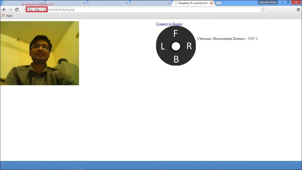
If you click on Connect to Robot, you will be able to see the live stream from the camera module on the screen. At the same time, just below the controller image, you will also be able to see the distance to the nearest wall in centimeters. This will automatically get updated after every 5 seconds.