
PROJECTS ELECTRONICS: FUN & FUNDAMENTALS
Easy, efficient, and effective.
![]() TIME: A WEEKEND
TIME: A WEEKEND ![]() COST: $$
COST: $$
LED Photo Lights
![]() I often have to take photographs of small objects — for example, when I’m selling items on eBay. Electronic flash is overkill for this kind of work, and video lights are bulky and hot. I decided to build miniature photo lights from small, efficient LEDs.
I often have to take photographs of small objects — for example, when I’m selling items on eBay. Electronic flash is overkill for this kind of work, and video lights are bulky and hot. I decided to build miniature photo lights from small, efficient LEDs.
On eBay I found complete LED reflector bulbs for just $3 each. They are plug-compatible and identical in size and packaging to the little 12V quartz-halogen spotlights often used in track lighting (although the LEDs have a cooler light temperature of 6,000° Kelvin — very similar to cloudy daylight). All the distributors were in China, but I’ve never had any problems ordering components from Chinese sources. Sure enough, within 10 days I received my lights.
NOTE You can download a full-size cutting and drilling template from makezine.com/34.
CAUTION Some AC adapters of this type deliver much more than 12V when not fully loaded. Therefore, avoid powering just one light at a time.
Since each unit was rated at 4W, I needed a 12V DC adapter that could supply at least 40W. Fortunately this kind of switching power supply is commonly available as a power source for laptops and LED displays. I found a 50W unit for $5.
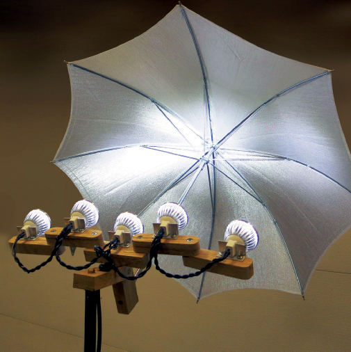
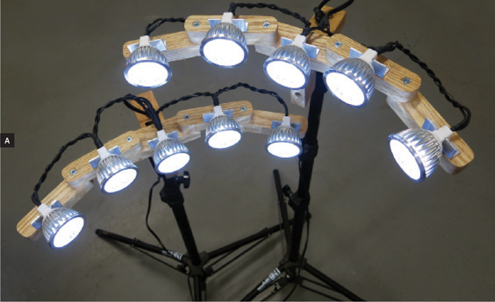
How to mount the lights? I wanted to use them in 2 sets of 5, so I could position each set on opposite sides of a subject. The angle of each light had to be adjustable, so I could focus their beams tightly around a smaller, closer object, or more widely toward a larger, more distant object. I also wanted to be able to angle the lights up and down, or even turn them backward to reflect against a photographic umbrella for diffuse, shadowless illumination.
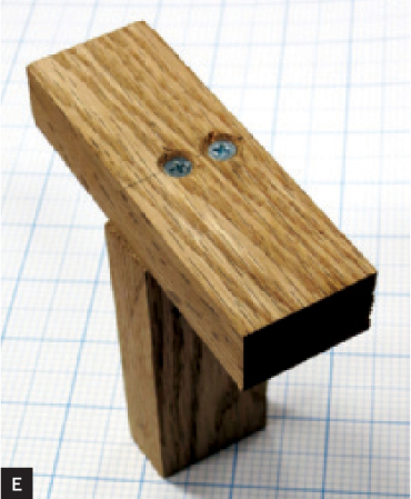
My design uses jointed arms (Figure A) made from ¾" oak and small aluminum angle brackets. My photographic light stands have 3/8" brass mounting pegs, so I simply drilled matching holes in the yokes to provide pushfit attachment. If your stands have threaded terminations, install a matching T-nut in each yoke and secure it, from the top, using a washer and a short bolt (3/8" or less) of the same thread.
I chose oak as my construction material because I wanted to use wood screws to secure the joints, and the screws would tend to work loose in softer wood. You can get an affordable piece of 3½"×¾" oak from The Home Depot, which also carries aluminum angles for making the brackets.
1. Shape the parts.
Figure B shows how to cut the wooden parts for one set of lights from a 3½" oak strip. The dimensions don’t have to be precise, so I didn’t bother to allow for the thickness of the saw cuts. I used a chop saw, but this requires great care when cutting relatively small pieces. A band saw would be safer. A handsaw is the safest, but will be slow as oak is hard to cut.
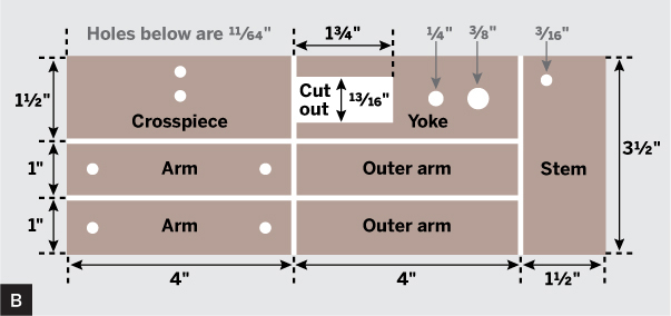
To fabricate the yoke section, make 2 parallel cuts, then a series of angled cuts to remove the notch in little triangular fragments. A band saw or jigsaw is good for this. A handheld keyhole saw will work if you’re persistent. A chisel won’t work well, as oak is too tough.
A drill press will ensure that each hole is drilled at precisely 90°. If you use a hand drill, secure each workpiece with a clamp or vise. Again, oak is tough, and these small pieces can easily spin out of control if you try to hold them by hand. Countersink each hole to accept the flat heads of the wood screws.
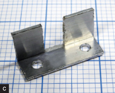
Cut 10 pieces from the aluminum angle, each 1½" long, and remove a rectangular notch about 3/8" wide from their centers (Figure C). This notch engages with grooves molded into the base of each light. If your lights are different, adjust the notch width to fit. Drill two 3/16" mounting holes in each bracket.
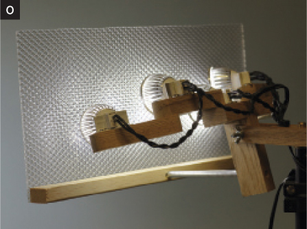
TIP If you want the option of adding a photographic umbrella, drill a 5/16" hole in the front edge of the stem section, and insert the shaft of the umbrella. Alternatively, you can diffuse the light by shining it through a piece of textured transparent lighting panel, as in Figure O.
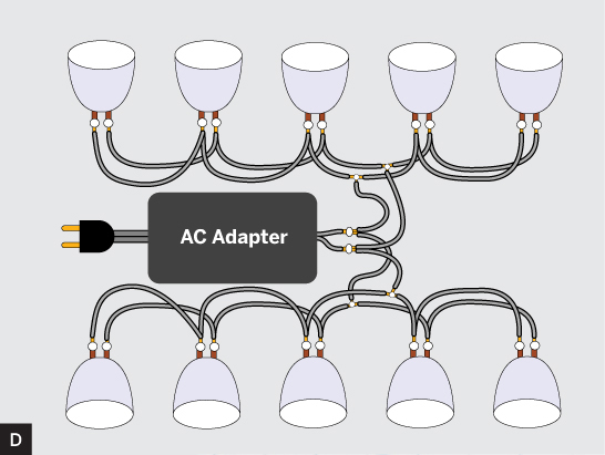
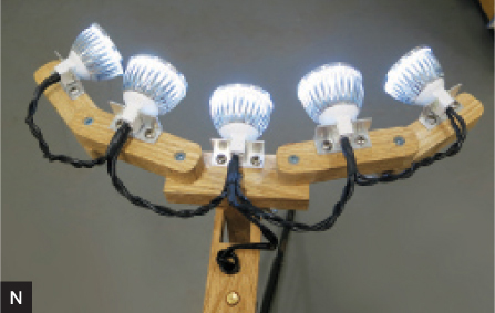
Figure D shows how the lights are wired. The actual wire lengths are up to you; you can cut them now or later when you wire the lamps in Step 3. See Figures N and O for actual wire usage.
2. Build the stands.
In this step, locate holes by using an awl to mark through each drilled hole, then follow with a 3/32" bit to create a pilot hole for the screw itself.
Attach the crosspiece to the stem as shown in Figure E. The screws are offset to avoid fouling the hole through the stem below.
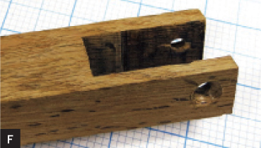
Drill 3/16" holes through the yoke (Figure F), and countersink one hole.
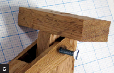
Use a bolt and wing nut to attach the yoke to the stem as in Figure G. Pack with washers if necessary, on one side only, so there is wood-to-wood contact (providing friction) at the other side. The assembly should feel sticky when you turn it around the bolt.
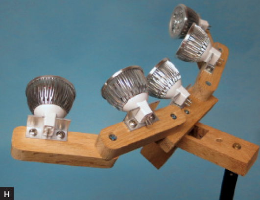
Round the ends of the arms with a file, then use 5/8" screws to attach a bracket to each, and to the central crosspiece. Insert the lights into the brackets, securing with epoxy if needed. Then attach the wooden arms to the central crosspiece (Figure H). One light set is now ready for wiring. Repeat this step to assemble the second set.
3. Wire the lamps.
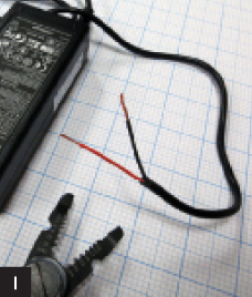
Your power supply probably has a plug on the end of its output cable. Chop it off and strip the wires (Figure I).
Cut, strip, and tin wire as needed to make the wiring harness connections and to attach the power supply. If you are using heat-shrink tubing, be sure to slide it over the wire before soldering (Figure J). Melt the solder to join the leads, then slide the tubing over the soldered joints and apply heat to shrink.

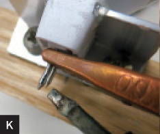
Tin each lamp pin before soldering. Use a copper alligator clip at the base of the pin as a heat sink (Figure K). Make sure the solder bonds well. Use a chisel tip for better heat transfer.
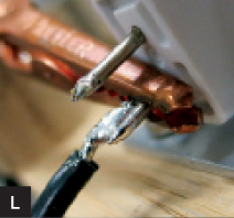
Strip and tin the lamp wire lead, slip heat-shrink tubing over it, and solder it to the pin (Figure L). Remove the heat sink and proceed to the next pin. Solder the lower row first, then the upper row.
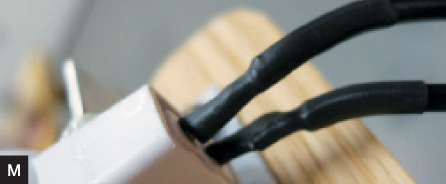
Test the lights, then slide the heat-shrink tubing over the soldered pin connections and apply heat (Figure M).
NOTE The spotlights I used are not sensitive to polarity. Double-check yours using a 9V battery and battery holder terminating in stripped wires. Touch the wires to the pins very briefly. If your spotlights only work with positive voltage on one side and negative on the other, they’re polarized. The molded pattern on one side of your dual-conductor wire will help you to maintain consistent polarity throughout the circuit.
Your finished lights should look something like Figure N. You can build a diffuser attachment (Figure O) using a prismatic plastic panel from a fluorescent light fixture. ![]()
Charles Platt is the author of Make: Electronics, an introductory guide for all ages. He is completing a sequel, Make: More Electronics, and is also the author of Volume One of the Encyclopedia of Electronic Components. Volumes Two and Three are in preparation. makershed.com/platt