
Hand-Crank Geiger Counter
Charge a high voltage tube using a simple mechanical oscillator.
I like mechanical systems. Even when it's not the most efficient solution, a machine with moving parts has flair that electronics often lack.

Gregory Hayes
HOW THE ELECTRONICS WORK

» The circuit applies 18V (from two 9V batteries wired in series) to the primary windings of the step-up transformer through the saw switch.
» The on-off cycling of power to the transformer creates inductive high voltage in the secondary winding, which passes through diode D1 and charges capacitor C1. The Zener diodes D2, D3, D4, and D5 regulate the voltage to 450V for the GM tube.
» When the capacitor is charged, we can siphon off 150V from the junction of D3 and D4 to light a neon bulb. The neon bulb indicates when the capacitor is fully charged and optimum power is going to the GM tube, at which point we can stop rotating the saw switch.
MATERIALS
» Diode, 1N4007 designated D1 in schematic
» Zener diode, 200V, 1N5281B D2
» Zener diodes, 100V, 1N5271B (2) D3, D4
» Zener diode, 51V, 1N5262B D5
» LED, subminiature, red D6
» Transistor, NPN, TIP120 Q1
» Neon bulb, 150V activation
» Speaker, 16Ω
» Capacitor, 2.2µF–3.3µF, 450V, film or equivalent C1
» Resistors, ¼w: 10mΩ (2), 4.7mΩ (1), 470kΩ (3), 220kΩ (1), 100Ω (1)
» Prototyping printed circuit board (PCB), about 2"×3" such as RadioShack #276-150, radioshack.com
» Hookup wire, 22 gauge, stranded
» Wood or plastic box, 5"×3½"×2" Make one, or shop for a “steampunk” box online.
» Plastic “saw” cut from ¼" acrylic part #PLSAW-01 from Images Scientific Instruments (imagesco.com), $8, or cut your own using the template at makezine.com/34
» Mini step-up transformer Images SI part #HVT-06, $8
» Geiger-Müller tube, 350V–475V, type SBM-20 Images SI #GMT-03, $60
» Lever switch, 250V 5A such as Mouser Electronics #540-D43L-R1ML, mouser.com
» Decorative brass gear (optional)
» Thrust bearing, ¼" ID, 9/16" OD #TB-025 or equivalent
» Brass or copper tubing, ¼" OD length to fit your machine screw
» Machine screw, #8-32 length depends on your enclosure
» Nuts, #8-32 (2)
» Flat washer, #8
» Split lock washer, #8
» Brass knob, small
» Binding post with screw to fit your knob
» Cable, 2-conductor, 16 or 18 gauge, 600V rating, cloth-covered such as Sundial Wire part #W182CTBKXXMNF, sundialwire.com
» Clear plastic tube, ¾" OD, ½" ID or greater, about 5" long
» Copper pipe fittings: cap, ¾" ID (1); reducer, ¾" to ¼" (1)
» Copper tubing, 1/8" diameter, about 24" total length
» Switch, SPST on-off toggle
» Battery snap connectors, 9V (2)
» Batteries, 9V (2)
TOOLS
» Drill and drill bits
» Hand saw or laser cutter (optional) if you’re cutting your own plastic “saw” for the switch
» Soldering iron and solder
![]() TIME: A WEEKEND
TIME: A WEEKEND ![]() COST: $$
COST: $$
MY HAND-CRANK GEIGER COUNTER IS not a truly historical design, but it does use an anachronistic “saw switch” as a mechanical oscillator. While I couldn’t remove all modern semiconductors from the circuit, I kept them to a minimum and used no integrated circuits.
1. Get a stylish enclosure.
Buy or build one. I found a “steampunk” style jewelry box for $22 on eBay.
2. Build the saw switch.
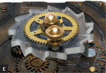
To create the free-spinning saw, I assembled the following parts: the acrylic saw, a top brass gear (for decoration only), an 8-32 machine screw of suitable length, two 8-32 nuts, a #8 split lock washer, a flat washer, a ¼" brass tube for the 8-32 machine screw to pass through, and a thrust bearing (Figure A).

Mount the small brass knob to the saw’s face using the binding post and screw, to serve as a cranking handle.
Locate a position for the saw on your enclosure’s lid, and drill a ¼" hole to accept the brass tube. Mount the saw temporarily in the hole, securing it with the nuts and washers inside the case.
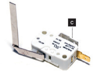
Now pinpoint a spot for the hole for the lever switch (Figure B). You’re mounting the switch on the bottom of the lid, so you’ll need to bend the lever so it will pass up through this hole.(Figure C). Position it so that when the saw is rotated clockwise, the lever is cleanly engaged and released by each tooth.

Gunther Kirsch
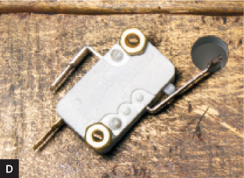
Remove the saw assembly and drill the hole. Reattach the saw and test-fit the lever of the switch (Figures D and E). You may need to widen the hole to allow clearance for the lever to operate cleanly.
When the hole is the right size and you’ve found the right position for the switch to engage the saw, mark the position of the switch and drill 2 holes for mounting bolts. Mount the switch, secure it with nuts, reassemble the saw, and check the operation of the whole mechanism (Figure F).

3. Build the detector wand.
For my detector wand, I used a Russian SBM-20 Geiger tube. Its stainless steel wall looks like copper and fits well with my design. The positive (+) terminal (for the central anode) is marked on the tube.
To connect the wand to the Geiger counter, I opted for a fabric-covered 2-conductor cable that has a nice antique look.
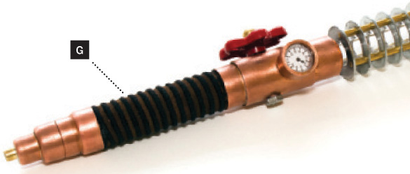
The wand is built from a 4" plastic tube with ½" inside and ¾" outside diameters, two ¾" ID copper pipe fittings that fit the plastic tube, and various decorative bits ’n’ pieces. The assembled wand, minus the GM tube, is shown in Figure G.
Solder the GM tube to the ends of the 2 cable wires. Cover the connections and the tube ends with clear silicone, for insulation, and let it dry overnight (Figure H).
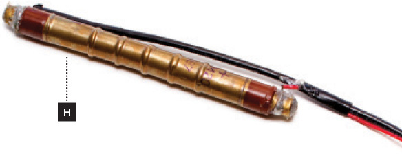
Thread the cable through the wand fittings, as necessary, and place the GM tube into the clear plastic part of the wand assembly. Secure the copper pieces with a little glue, epoxy, or silicone. Silicone is a good choice if you want to disassemble the wand for later upgrades or repair.
4. Assemble the Geiger counter.
Assemble the electronics on a prototyping PC board, following the schematic on page 125.
Drill a hole in the case to accept the wand cable, or the socket if you’re using one. If you use a socket, be sure to connect it to the circuit’s ground.
If you’re not using a socket, tie a strain-relief knot in the wand cable inside the case. Then connect the wand’s (+) wire to resistor R1 on the circuit board, and its (–) wire to R4 and capacitor C2, as shown in the schematic.
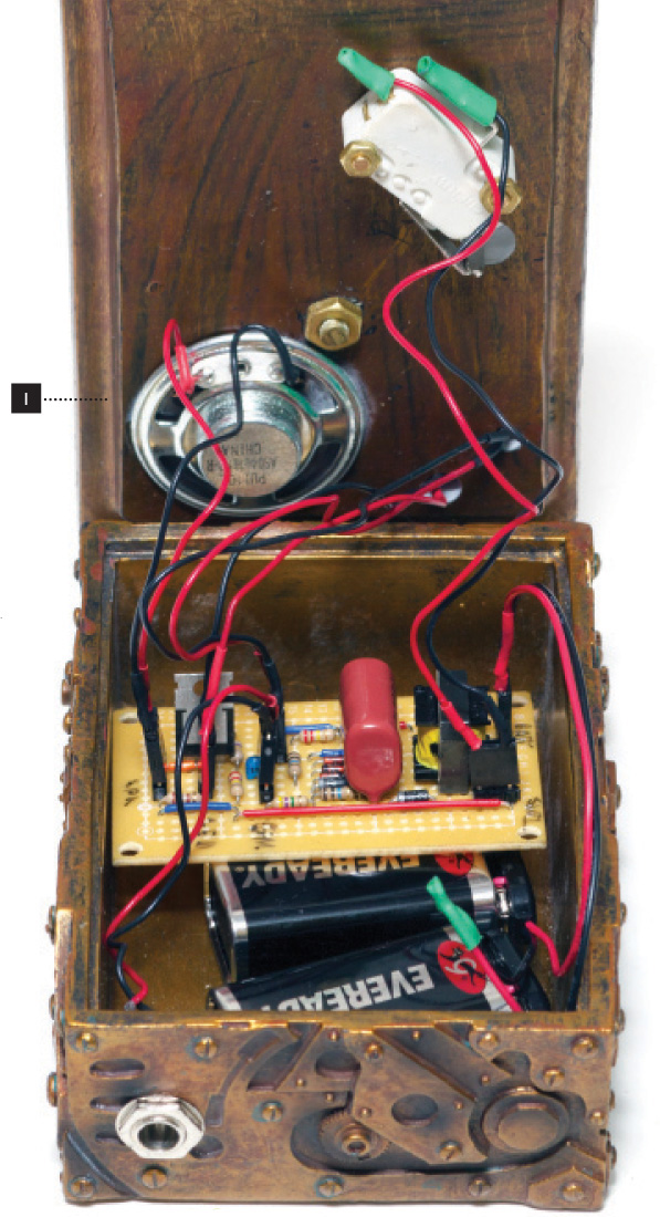
Drill holes in the lid to mount your LED, neon bulb, and speaker. Space is tight, so measure carefully before you drill. Finally, drill a hole in the side of the case for your on-off switch, and stuff everything into the box (Figure I).
Operation
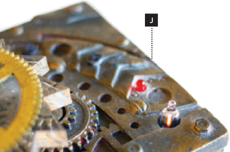
Turn on the power from the batteries. Rotate the saw switch at a medium pace for 1 minute or so until the neon bulb lights up (Figure J). Bring the wand close to a radioactive source. You should see the LED pulse and hear the speaker click every time a radioactive particle is detected.
When the neon light goes out, the counter will still have enough voltage on the capacitor to power the GM tube, but it’s not as reliable. Crank it up again with the saw switch. When you’re done cranking, be sure to turn off the power to avoid draining the batteries. ![]()
John Iovine is a science and electronics tinkerer and author who owns and operates Images SI Inc., a small science company. He resides in Staten Island, N.Y., with his wife and two children, their dog, Chansey, and their tabby cat, Squeaks.