
Chapter 9
Creating Logical Systems
Creating and managing systems is the key to getting Autodesk® Revit® MEP to work for you. Systems represent the transfer of information between families. They range from supply air to refrigerants to laboratory gases to anything else a building needs to operate.
In this chapter, you will learn to do the following:
- Create and manage air systems
- Create and manage piping systems
- Manage display properties of systems
Managing Systems
Systems are the logical connection between elements in the model. They are the link between the air terminal, the variable air volume (VAV) box, and the air handler, and they represent an additional layer of information above the physical connections made with duct and pipe. Without systems, ducts and pipes act only as connections between two points. Systems are needed to generate the bigger picture and allow you to manage the elements on a building-wide level. You can create systems to represent supply, return, and exhaust air as well as plumbing, fire-protection, and hydronic piping. You can also create systems to represent other uses of duct and pipe outside the predefined types included in Revit MEP 2013.
Systems aid in the documentation of a model. Because elements across the entire model are linked together, tags and other properties can be managed quickly and accurately. The best example of this is using a pipe tag that includes not only the size but also the system abbreviation. Tagging any piece of pipe connected to the system, in any view, will immediately generate a complete and accurate annotation.
Why Are Systems Important?
Managing systems is the only way to separate, say, a cold water pipe from a hydronic pipe. If you can't separate the two, you will simply not be able to produce sheets showing certain systems and hiding others. Prior to Revit MEP 2012 you had to create systems manually, and it was a fairly time-consuming process, especially keeping all of your systems properly organized throughout the design. But since Revit MEP 2012 you are able to create duct runs in a supply/return or exhaust system without actually creating a system in the first place. The neat thing about this is that the system can be changed on the fly. Of course, if a duct system is created by using the Generate Layout tool, the ducts assume the system of the host mechanical objects. Even though the ducts are associated with a system, managing space air quantities will need to be done externally. Entering all the information needed to accurately represent the mechanical systems in a building may seem like a daunting task at first, but the benefits of having all the information in one place and directly in front of the user can lead to more-accurate designs. Instead of the user flipping between a building-load program and a duct-sizing chart (or wheel) and trying to keep track of which terminal box is serving which space, systems can handle all of that for the user. By feeding Revit MEP 2013 the load information, calculated internally or externally, and creating an air system for a space, the user can quickly determine the cubic feet per minute (CFM) required at each air terminal with a schedule or a custom space tag. The airflow will then be assigned to the terminal box, and the space that it is serving can appear in a schedule. One program can handle all of these tasks, which the user would have to do anyway.
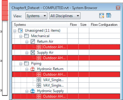
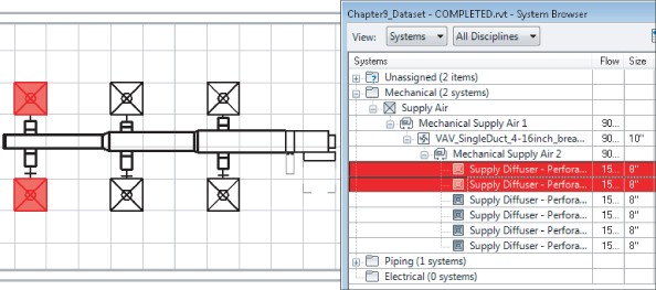
Using connected systems also carries a performance boost for Revit MEP. Even if systems are not being specifically set up, Revit MEP is using systems behind the scenes to keep track of all the information in the model. Revit MEP 2012 was the first version where you were allowed to enable or disable calculations per system type (Supply, Return, Exhaust, and so on), thus increasing the performance of the Revit model. This can be done from the Properties menu of the systems. All elements get placed on default systems based on the type of connector: supply air, return air, hydronic supply, and so on. This can be seen in Figure 9.1, which shows that objects are registered as Unassigned until they are connected.
Figure 9.1 Unassigned system objects
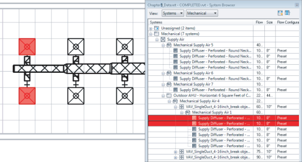
In the System Browser, if you expand the system tree, you can see that when an object is selected, the corresponding item is highlighted in the drawing area. In Figure 9.2, the objects are selected in the drawing area and highlighted in the System Browser.
Figure 9.2 Selecting in the drawing area
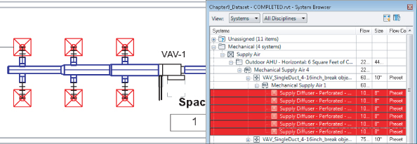
Conversely, selecting items in the System Browser highlights the objects in the drawing area, as long as the items are actually visible in that view (see Figure 9.3).
Figure 9.3 Selecting in the System Browser
Mechanical Settings
Before you can jump in and start creating systems, you need to set up several things to ensure that the systems work as they should. There is nothing wrong with the default settings, but every firm is different—each has its own standards, procedures, and often different design requirements. Most companies have developed standards over the years, and these are good guidelines to follow when using a new application such as Revit MEP 2013.
The Mechanical Settings dialog box, accessed from the Manage tab's Settings panel, contains some of the most critical settings for using systems in Revit MEP 2013 (see Figure 9.4). This dialog box was briefly covered in Chapter 2, “Creating an Effective Project Template,” but a more in-depth look is needed so that you can understand how these settings affect systems in Revit MEP 2013. All of these settings should be established in your company's project template. Changes to them should be discussed with the Revit team as well as the CAD manager, because visibility and graphics can be dramatically affected by a minor change in this dialog box.
Figure 9.4 Mechanical Settings dialog box
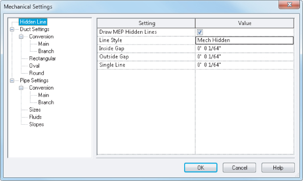
Several settings really affect systems graphically. For example, by choosing Duct Settings ⇒ Hidden Line, you see Inside Gap, Outside Gap, and Single Line. By default, each one of these is set to 1/16″ (0.5 mm). By changing the numeric size of each one of these parameters, you can get a different look that will help match your existing standards.
System Browser
The System Browser, shown in Figure 9.5, summarizes all the systems currently in the model. If that were all that it did, it would be a useful design tool. You could keep track of all the air and water in the building and see your system totals at a glance. But the System Browser in Revit MEP 2013 takes this idea a step further; it is a live link to the components in the system as well as their parameters. You have full control to modify the airflows, equipment types, and diffuser selection, all from a single window.
Figure 9.5 System Browser
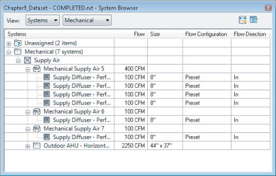
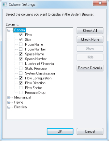
You can access the System Browser from the Analyze tab or the keyboard shortcut F9. The first thing you should set up are the columns it displays. The System Browser can get very large, so a second monitor is helpful. You can access the Column Settings dialog box by clicking the Column Settings button in the upper-right corner of the dialog box, which gives you an expandable list of the information that can be referenced in the model (see Figure 9.6).
Figure 9.6 Column Settings dialog box
Obviously, not every parameter will be filled out for every part of the system, and some of the parameters will not be useful on a day-to-day basis. The columns you choose to display will rely on your personal preferences and how you model your systems. For example, Space Number and Space Name will populate only if the element and space touch. If spaces are bound by the ceiling, and terminal boxes exist above the ceiling, they will not be associated with a space. You will need to use the Show command to find lost terminal boxes. To do this, right-click any element in the System Browser and select Show.
Ideally, every connection on every piece of equipment would be associated with a system, and the Unassigned system category would be empty. This may not be realistic on a large job or where manufacturer content is being used. You may not model every condensate drain, but if the manufacturer has provided a connection point for it, there will be a listing in the System Browser. If your firm decides to use the System Browser to carefully monitor the systems and elements in the model, you may want to eliminate connectors that you will not be using to keep things clean. To do this, you will have to create a duplicate family and remove the connectors you do not want to use.
Setting Up Air Systems
Duct connectors in Revit MEP allow the user to connect ductwork to a family that may represent an air terminal, fan, VAV box, air handler, or chilled beam. Duct connections can also be used as a source for boiler combustion air and flues. There are many different applications of duct connections beyond a simple supply air diffuser. In this section, you will learn how to set up many different kinds of systems using duct connections.
Understanding Parameters
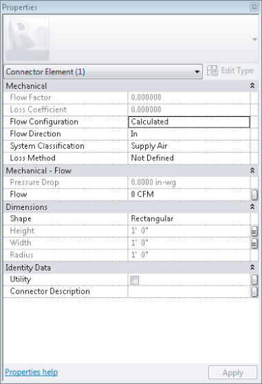
It takes a good understanding of the parameters besides height and width (or radius) before you can set up complex air systems. There are 14 parameters associated with a duct connector when its System Type is not set to Fitting. Not all of the 14 are active all the time (see Figure 9.7).
Figure 9.7 Parameters for duct connection
If the connector System Type is set to Fitting, the connector has only six parameters. Revit MEP has several System Classification types available for duct connections that facilitate system creation and view filters within a project (see Figure 9.8).
Figure 9.8 System Classifications for duct connections
Starting at the top, here is an explanation of each duct connector parameter shown in Figure 9.7:
Flow Factor
This parameter determines the percentage of the system flow that will be seen by the connector. It is available only when Flow Configuration is set to System. It is useful when using multiple devices, each of which is sized for part of the load.
Loss Coefficient
Available only when Loss Method is set to Coefficient, this parameter is used in conjunction with the Flow parameter to determine the pressure drop.
Flow Configuration
This parameter determines how the connector flow will be calculated.
Calculated
This setting calculates airflow downstream of the connection, and sets the Flow parameter to the sum of those flows. It is particularly useful for the outlet connector of VAV boxes.
Preset
No calculation is needed, and airflow is set to the Flow parameter. This can be used for the inlet connector of VAV boxes.
System
This setting is similar to Calculated, but the flow factor comes into play. It is best used for splitting the total system airflow between air handlers.
Flow Direction
Flow Direction can be set to In, Out, or Bidirectional. This direction is referring to the direction that air is moving relative to the connector, not the direction in which the air is flowing. For example, a supply air diffuser should be set to In because the air is flowing from the connected duct into the connector of the diffuser. An exhaust grille would be set to Out because air is coming out of the connector and entering the system.
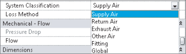
System Classifications
Here, the most appropriate system classification is chosen for the application. Supply Air, Return Air, and Exhaust Air are all pretty self-explanatory, but they also have other uses.
Supply Air
Air that is to be supplied to a space can also be used to model outside air, which is also known as air to be delivered to a space or air handler.
Return Air
Air that is being returned from the space back into the system is called return air. It can also be used in place of relief air, but exhaust makes a little bit better of a candidate.
Exhaust Air
Air that is destined to leave the space as well as the system is called exhaust air. This is the best option for modeling relief air.
Other Air
Other Air seems like a logical candidate for relief air or outside air; however, systems cannot be made with Other Air. In addition, if you want utilize CFM calculations, you shouldn't use the Other Air system, because it doesn't do those calculations.
Fitting
The Fitting system type is merely a pass-through connection; there is no effect on the airflow or definition of the system.
Global
Global connections can be either Supply Air, Return Air, or Exhaust Air. When you are creating the system in the project, you will be given the opportunity to select what type of a system it should be. Fans are a good example of equipment that may use global connections.
Loss Method
Not Defined, Coefficient, and Specific Loss are the options here, and Coefficient and Specific Loss each activate another parameter. Specific Loss should be used where the loss is known from a catalog or cut sheet. The pressure loss is taken literally as the entered value for Pressure Drop.
Pressure Drop
This can be entered as a static value or linked to a family parameter. Units are handled in the Project Units dialog box (Manage ⇒ Project Units). Pressure Drop becomes active when Loss Method is set to Specific Loss. It can be linked to a family or shared parameter.
Flow
Values for the flow associated with the connector are dependent on flow configuration. It can be linked to a family or shared parameter.
Shape
The Shape settings of Rectangular and Round determine which dimension parameters are active and the shape of the duct that will connect to the connector.
Height
Height is simply a dimension of the connector. It can be linked to a family or shared parameter.
Width
Width is simply a dimension of the connector. It can be linked to a family or shared parameter.
Radius
Radius is similar to Height and Width; however, be careful to use the radius and not the diameter when linking to a family or shared parameter.
Utility
This indicates whether the connector is exported as a site utility connection point to an Autodesk Exchange file (ADSK). It can be linked to a family or shared parameter.
Connector Description
The option to assign a name to connectors shows up primarily when using the Connect To feature. It also appears when connection points are in the same vertical plane. It is a good practice to give your connectors a description so that they can be easily identified in families with multiple connectors. It can be linked to a family or shared parameter.
Creating Mechanical Systems
Now that you have reviewed the parameters of the mechanical systems that exist, you will now learn how to apply them in a simple exercise:
Figure 9.9 Selecting a supply diffuser
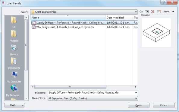
Figure 9.10 Loading a VAV single-duct family
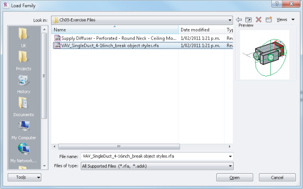
Figure 9.11 Placing ceiling diffuser into ceiling grid
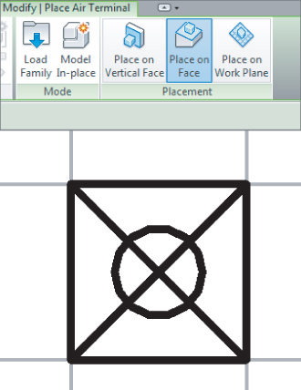
Figure 9.12 Changing elevation offset for the correct elevation of equipment
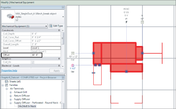
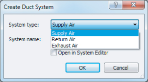
Figure 9.13 Creating a supply duct system
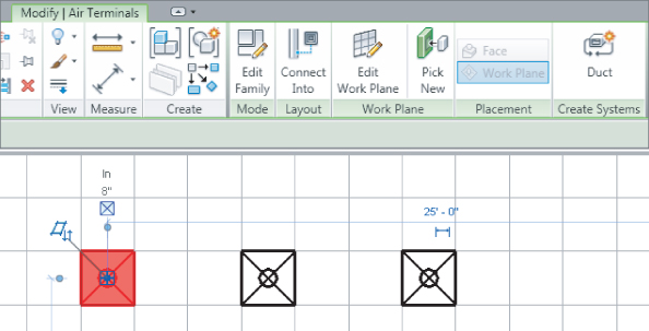
Figure 9.14 Create Duct System dialog
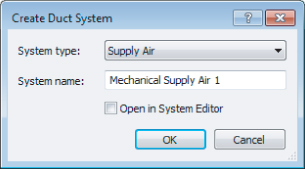
Figure 9.15 Editing supply duct systems
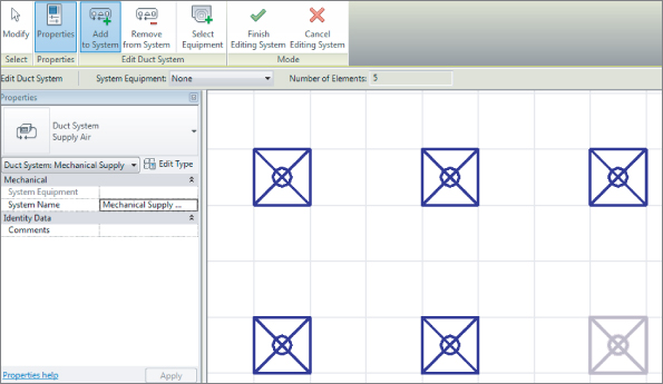
Figure 9.16 Selecting in System Browser
Now that you have created your system, you can route your ductwork and it will take on the characteristics of the system parameters you set up. Understanding how to make mechanical systems will offer you the benefit of being able to create any duct system you may need for your design. For further instruction on how to route ductwork, refer to Chapter 10, “Mechanical Systems and Ductwork.”
Another new feature that was introduced for the first time in Revit MEP 2012 was the ability to automatically create systems on the go as you route your ductwork/pipework. You no longer need to create systems manually as in the previous exercise. Simply connect the supply duct to any diffuser and watch it become part of that system. But disconnecting the duct that “pushed” the system to the diffuser will not remove the diffuser from the system. Therefore, understanding how to create and manage systems manually will still be necessary.
Setting Up Piping Systems
Mechanical piping benefits greatly from systems in Revit MEP 2013. Graphics, annotations, flow, and pressure loss can all be handled with a small amount of setup in your project template. Pipe systems also allow filters to apply to all components in the system, including the fittings. As discussed earlier in this chapter, Revit MEP 2012 introduced new enhancements in how systems behave, which are still valid for Revit MEP 2013. Also, the enhanced System Browser acts as a graphical pointer to the designer with regard to how objects are connected in systems; it also has a huge benefit on how the actual systems perform.
The first of these benefits is the ability to predefine the system in which pipes (and ducts) are created, allowing layouts to be designed without the need to set up systems in the first place. This allows the designer to create Hot Water (HW) and Cold Water (CW) pipe runs with graphical filters already in place to display the different systems being created.
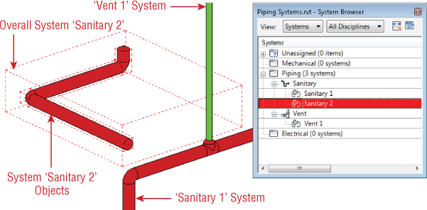
Second, this allows for different systems to be interconnected. In previous versions of Revit MEP, it was necessary to employ a variety of workarounds in order to have, for example, a sanitary pipe system connected to a vent pipe system. Since Revit MEP 2012, all designers have to do is specify the system type they want to create. Figure 9.17 displays Sanitary and Vent pipe systems with the system Sanitary 2 selected. When working with multiple systems that are connected, it is important to note that a fitting, accessory, or equipment is needed between the two pipes/ducts in order for the separation of the systems to work. When the system change occurs at an elbow or tee, all is good, but when you want to change the system continuing the pipe/duct in the same direction as the original one, you need to use the Split tool, which will insert a coupling fitting, and therefore you can have two different systems.
Figure 9.17 Dual pipe systems
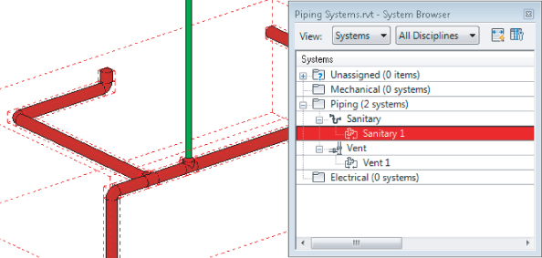
As the design progresses, systems may need to be merged with these new “systemless” systems. All the user has to do is connect the two systems together. Figure 9.18 shows that after the two sanitary systems are joined, they effectively become one system with no further interaction required.
Figure 9.18 Merged systems
Understanding Parameters
Parameters for piping are similar to the parameters for air systems such as Flow Factor, Calculated, Preset, Flow Direction, and so on. The available pipe system types are as follows:
Hydronic Supply
This pipe system can also be used for chilled water supply, cold water supply, steam, hot water supply, and process piping supply.
Hydronic Return
This pipe system can also be used for chilled water return, cold water return, steam condensate, hot water return, and process piping return.
Sanitary
This pipe system can also be used for grease waste, oil waste, storm drainage, acid waste, contamination drainage, and condensate drainage.
Domestic Hot Water
This pipe system can also be used for different hot water systems such as 140-degree, 110-degree, and tempered water.
Domestic Cold Water
This pipe system can also be used for filtered water, deionized water, and chilled water for remote drinking fountains.
Other
This pipe system can be one of the most utilized pipe systems if you have a large piping project. This can be used for medical gas piping, vent piping, liquid propane piping, natural gas piping, air piping, or any system that doesn't require GPM calculations.
Fire Protection
This can be used for the building sprinkler piping, or it can be used for the utility fire protection coming into your building to connect the base of your fire-protection riser.
Wet Fire Protection
This pipe system type normally is used for the layout of the piping from the riser to the sprinkler head layout.
Dry Fire Protection
This pipe system is used for layout from the fire riser to the sprinkler head or standpipe to keep the system from freezing.
Pre-Action
This pipe system can also be used for a deluge system.
Fire Protection Other
This pipe system can be used for glycol antifreeze systems and for chemical suppression systems.
Creating Pipe Systems
You will need to define pipe types, load some fitting families, and have something to which they will all connect to create pipe system. Equipment is the source of the system, and the pipe and fittings connect everything. It seems pretty simple, but there are several things to consider when setting up the components of a pipe system.
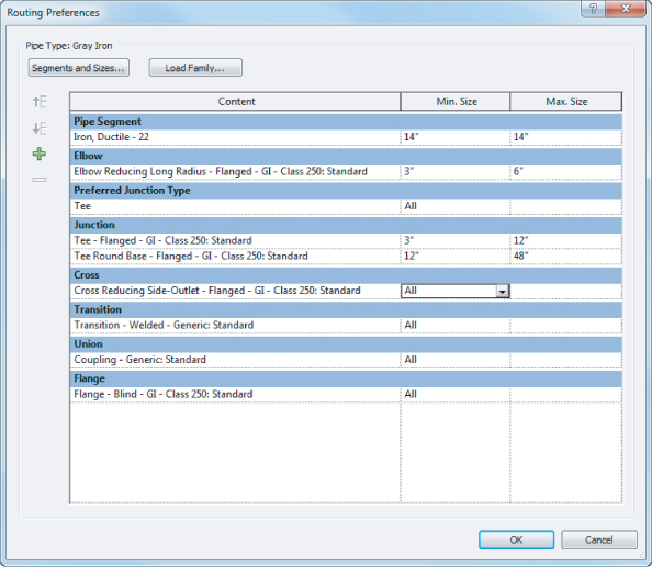
The Pipe Type Properties in Revit MEP 2013 have been completely reorganized (see Figure 9.19). Now you have the ability to assign Routing Preferences by size. For example, you may want to use a certain type of fitting only when routing pipes under 6″(152 mm) and another type of fittings for pipes over 6″ (152 mm) (see Figure 9.20). In addition, the old usage of Materials has now been moved under Routing Preferences and renamed to Pipe Segment. The pipe types should all reflect real-world values and the company standards and specifications. Even if you are not using Revit to size or lay out pipe automatically, not setting up the appropriate pipe types can cause headaches down the road. Pipe types should not be left at Standard and PVC. Those hardly cover the necessary piping that a building requires and, more importantly, the plumbing and mechanical engineering will be fighting over what fittings should be standard and what materials should be used. Mechanical piping and plumbing piping should have their own pipe types. Even if exactly the same materials and fittings are being used, there may be changes later, and splitting out pipe types late in a project will undoubtedly eat up a lot of time. This is one area of Revit MEP that enables you to have as many types as you want, so take advantage of it.
Figure 9.19 Pipe Type Properties
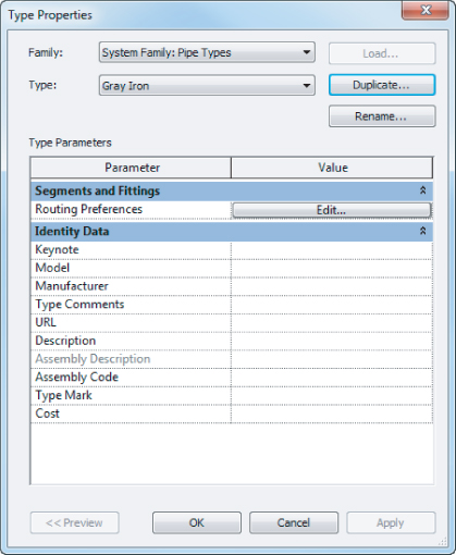
Figure 9.20 Routing Preferences
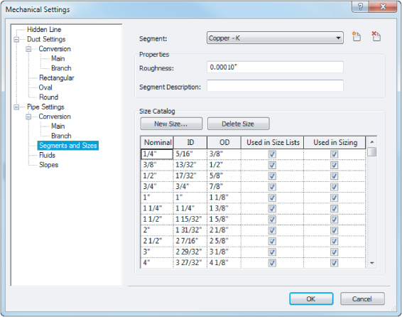
Pipe Segments And Sizes are set up in the Mechanical Settings dialog box (see Figure 9.21), and similar to pipe types, they should be separated for plumbing and mechanical piping. In many instances, you would probably be fine using the same material and sizes, but when differentiating them is as simple as selecting the Add Material icon and selecting a source from which to copy, there is no reason not to create as many sizes and materials as needed. All of these settings should also be determined by using the company standards and specifications. It may seem tedious to set up, but if the inside diameter of a 6″ (152 mm) hot water pipe is not true, and you are using a lot of it, your pipe volume calculations can be skewed.
Figure 9.21 Pipe sizes
Fittings should be set up after sizes and materials for a couple of reasons. First, the connection type needs to match. A solvent-welded PVC fitting and a flanged steel fitting are vastly different. Second, the fittings need to be defined at all the available sizes for that type of pipe; if it goes down to 3/8″ (10 mm) or up to 36″ (914 mm), the fitting needs to accommodate. Fittings are specific to the type of system, which is another reason to separate pipe types for plumbing and mechanical uses.
Hydronic systems have value even if the equipment is not piped together. Terminal box reheat coils are a good example, because details generally cover their final connections. By simply adding all the terminal boxes to a hydronic supply and hydronic return system, you will be able to see the total flows for the entire model. You can use this flow summation to ensure that systems are adding up to what you expect and to compare flows between systems.
Creating Fire-Protection Systems
Fire-protection systems in Revit MEP are a sort of hybrid between air systems and hydronic systems. Sprinklers, from a system standpoint, are similar to air terminals. Sprinklers are designed to distribute a fluid evenly over a given area, with pressure as the driving force of distribution. In the case of fire protection, water is the fluid, and the fire pump or city connection provides the pressure.
The key to a good, manageable fire-protection system is the families. Decide what type of system you will be using, and make sure appropriate families are developed before you or other users start laying out components. Revit MEP does have the ability to load a family in the place of another, but that tends to cause issues with system connections, pipe connections, and hosting. Sprinklers, standpipes, hose cabinets, and fire pumps may have to be created for the systems to work properly.
Setting Display Properties of Systems
Revit MEP 2012 was the first version to introduce system families for duct and pipe systems. These can be found in the Project Browser under Piping System and Duct System.
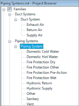
System families can have additional types created in the same way as other loadable families, by right-clicking any one of the existing types in the Project Browser and duplicating it. It is important that you choose carefully—a duplicated Domestic Hot Water piping system cannot be changed later to a Domestic Cold Water piping system.
With these new system families come new parameters: System Abbreviation and System Classification. Beginning with Revit MEP 2012, you have the ability to tag any pipe (or duct) and refer to the system type of what may be a system with no equipment assigned. You could not achieve this in previous releases without manual workarounds.
System Filters
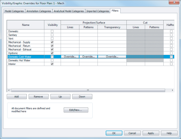
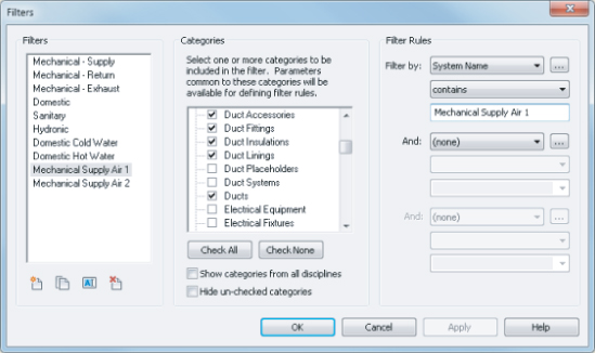
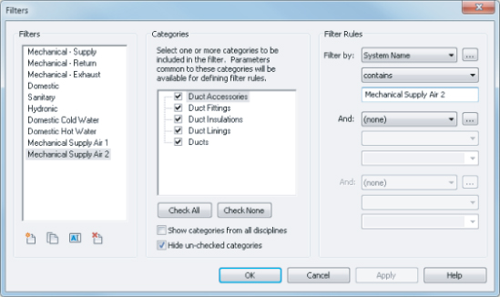
To set up system filters, you need to select the View tab on the ribbon and then choose Visibility/Graphics ⇒ Filters (see Figure 9.22). You will then notice that, in the Filters dialog box, there are several filter names that are in Revit MEP by default.
Figure 9.22 System filters
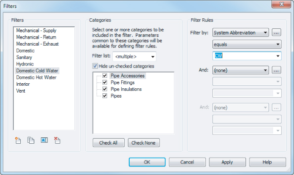
You will also notice that there are categories that have different elements selected. These are the items you want to have affected by the filter. Next, you will notice under Filter Rules that, by default, System Classification is selected. Because of the large number of filters that are normally created for a project, you should change the Filter By setting from System Classification to System Abbreviation. This will help to identify and separate your systems properly. To create new system filters, the easiest method is to select an existing system filter and then click the Duplicate icon. Once the system filter is duplicated, make sure the proper category elements are selected and then rename the filter rule to the name by which you want to filter.
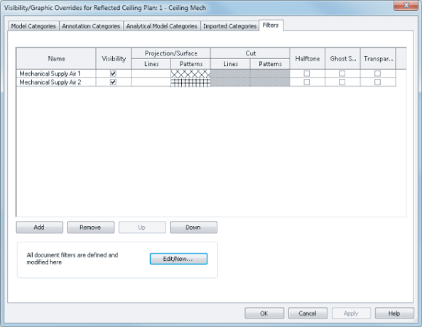
To apply these filters to your views, you can go to the View tab on the ribbon and then select Visibility/Graphics. Next, select the Filters tab (see Figure 9.23).
Figure 9.23 View filters
Once you have selected the Filters tab, click Add. This brings up the filters that you have created, so select the filters that apply to your project. Once the filters are loaded, you can turn on and off the filters and adjust line weights, colors, and patterns.
Mastering filter options will give you the ability to create your models with the standards that your office has developed over years of producing CAD drawings.
The Bottom Line
Create and manage air systems.
Knowing how to manage air systems can help productivity by organizing systems so that items can be easily interrogated to verify that the systems are properly connected.
Master It
True or false: Outside air cannot be modeled because there is no default system type from which to select.
Create and manage piping systems.
By understanding how to change and manage piping systems, the user can create and maintain different systems effectively.
Master It
A designer has been asked by an engineer to create a Grease Waste system to accommodate a new kitchen that has been added to a project. What would be the quickest way to accomplish this feat?
Manage display properties of systems.
Filters and Visibility settings can help the user show the intent of the layout.
Master It
A plumbing designer has just created a piping system, and now the engineer has decided that the Grease Waste piping should appear as a dashed line. How would the designer accomplish this?