
Chapter 16
Fire Protection
Fire protection is probably one of the least mentioned features in Revit. Fire protection designers use a variety of methods and software programs to lay out fire protection systems. There are considerable benefits to doing this process in Autodesk® Revit® MEP 2013, including coordination and clash detection with other services and building elements.
In this chapter, you will learn to do the following:
- Place fire protection equipment
- Create fire protection system
- Route fire protection piping
Understanding the Essentials of Placing Fire Protection Equipment
Proper planning in placing fire protection equipment is essential when trying to create a productive layout with Revit MEP 2013. You should plan to have most of your equipment roughly located during the schematic design phase of the project, which helps with productivity and coordination with other disciplines. You will need to use proper design methods to verify whether a fire pump is required on a project.
Although pump manufacturers are starting to provide Revit content, they are still few and far between. If you look under Imperial Library ⇒ Fire Protection, you will find several components that can be used out of the box for fire protection. Others can be found as Mechanical components or under Piping. For example, the backflow preventer is located under Imperial Library ⇒ Pipe ⇒ Valves ⇒ Backflow Preventers.
Point of Connection
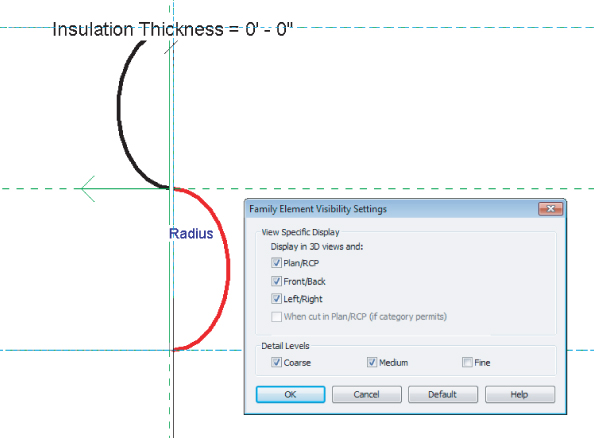
You should start your model by understanding where your water supply starts. Normally, a civil engineer will provide location details. There is no special need for a model element to represent this point of connection (POC). You can simply begin drawing pipe at the appropriate location. However, you may want something to help identify this POC. You can display this information in your design model either by creating a water meter family or modifying an end cap family. To modify an existing family to indicate the water inlet point, do the following:
Figure 16.1 Fire protection point of connection
Fire Pump Assembly
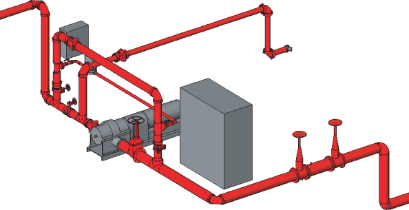
You should try to preassemble as many of the fire protection components as possible to help with production time. Figure 16.2 shows a fire pump preassembled so that you would have to change out only certain components—for example, changing the pump for a smaller or larger pump, depending on what is called for by the calculated fire flow demand.
Figure 16.2 Preassembled fire pump
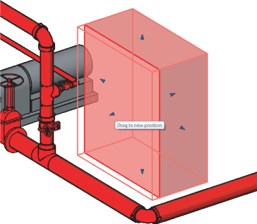
To create a preassembled fire pump, do the following:
Figure 16.3 In-place component
Fire Riser Assembly
Fire risers for most small projects are assembled from the same basic parts. The ideal way to handle assemblies like this is to create them as a Mechanical Equipment family. This will allow you to place a single family quickly during schematic design. The placement of the fire riser is crucial for understanding where the fire line will need to be routed and for space planning within the building. This family can be constructed from nested valve and fitting families along with extruded solids to indicate pipes (see Figure 16.4).
Figure 16.4 Fire riser assembly
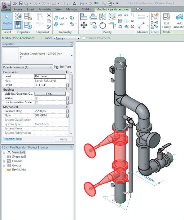
This family is created by nesting pipe fitting and pipe accessories families. To review what components make up this family, do the following:
By assembling the riser as a single family, you can coordinate the location in which it is being installed and then start planning how to route your piping. This family does not need to be parametrically flexible. The assembly will still speed your production for future projects even if it needs to be edited manually for different sizes and configurations.
Sprinkler Heads
Now that you know about fire pump assemblies and how to create a standard fire riser, you can start planning for the type of fire protection sprinkler heads you will need to use for your model. Within Revit MEP 2013, there are several types of sprinkler heads from which you can choose. The different family types of sprinkler heads are hosted and nonhosted.
Hosted sprinkler heads are normally face-based families. When using these types of families, you will need to locate them on a surface. These locations depend on the installation and the type of sprinklers, which could be wall, ceiling, slab, or soffit mounted. These surfaces can be part of the linked architectural model or reference planes defined within your fire protection model.
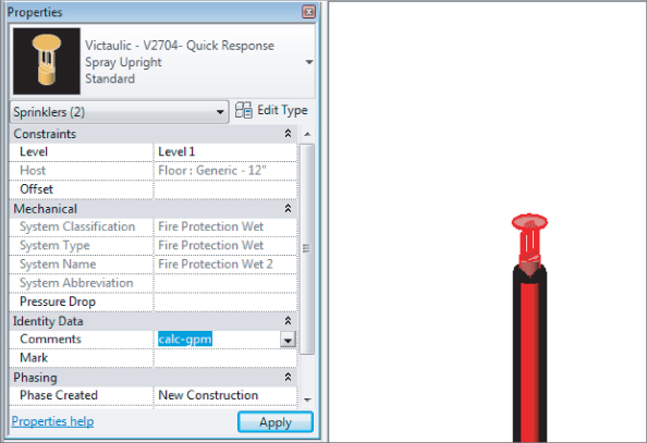
Nonhosted sprinkler families must have the Offset height parameter set to locate the heads at the proper elevation (see Figure 16.5).
Figure 16.5 Nonhosted sprinkler heads
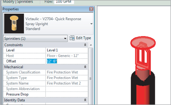
Upright sprinkler heads are normally nonhosted because they are located in spaces that do not have ceilings, such as storage rooms or mechanical closets. If you do not set the offset height, the heads will come in at a default of 0″ (0 mm), which could locate the heads on or below the floor level. This is easily fixed by clicking the button to place a sprinkler and changing the Offset setting in the Properties palette before placing the family.
Creating Fire Protection Systems
There are several options for the types of fire protection systems that can be created. They are as follows:
Fire Protection
This can be used for the building sprinkler piping, or it can be used for the utility fire protection coming into your building to connect the base of your fire protection riser.
Wet Fire Protection
This pipe system type is normally used for the layout of the piping from the riser to the sprinkler head when freezing is not expected.
Dry Fire Protection
This pipe system type normally is used for the layout of the piping from the riser to the sprinkler head when there is potential for damage from freezing.
Preaction
This pipe system can also be used for a deluge system.
Fire Protection Other
This pipe system can be used for a glycol antifreeze system, and it can also be used for a chemical suppression system.
You can also refer to piping systems in Chapter 11, “Mechanical Piping,” for more information. When creating a fire protection system, one thing to remember is that the system will not calculate and autosize as will domestic water systems. The main reason is that fire protection systems have no true way of selecting and calculating which heads are in the highest demand.
If the system were to try to calculate by GPM, it would account for every sprinkler head on the system, which would grossly oversize the system. Also, the fire protection system at this time has no effective way of calculating the water pressure as it goes higher in elevation.
Creating a Fire Protection Wet System
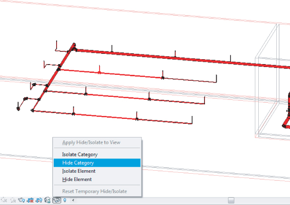
When creating a fire protection wet system or one of the systems previously mentioned, you would first select all the components that are going to be associated with that system. Selecting these items may be easier if you use the Temporary Hide/Isolate command to hide those model categories that you do not want to include (see Figure 16.6). You can also use the new feature Selection Sets in Revit MEP 2013 to remember the selected items for future usage. After you have selected all components that you want, simply click the Save button from the Selection panel located under the Modify | Multi-Select tab. When nothing is selected you can find the tool under the Manage tab.
Figure 16.6 Adding sprinkler heads to a system
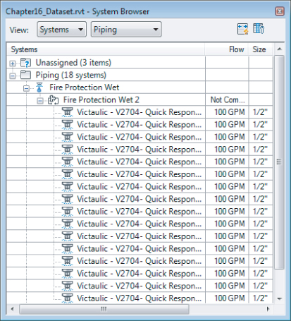
In case a system has already been started, you can add to the system by selecting a component on the system. Click Piping Systems ⇒ Edit System ⇒ Add To System, and then window all the items you want to add to the system. If this is done correctly, you should see all the items in the System Browser under the system you created (see Figure 16.7). Just keep in mind that when you start routing your pipes between the sprinkler heads, Revit MEP 2013 will automatically add those heads to the same system. This was not the case in older versions, where you had to organize the systems manually before you started drawing the pipes.
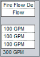
Figure 16.7 Fire protection system in the System Browser
Filtering Fire Protection Systems
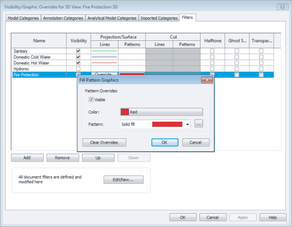
Once your fire protection system is created, you will need to make sure the piping will filter correctly. You will use filters to separate the fire protection pipes from all other pipes in your Revit model. This will assist you with turning off all other pipes from the fire protection views and sheets. For controlling the linetypes and linecolors of your systems, you should use Piping Systems, located in the Project Browser under Families. From the Piping Systems Properties you can assign the color, linetype, and system abbreviation for your systems. From the same dialog box you can also disable the flow calculations for certain systems (vent, medical gas, and so on). This will increase your Revit project performance, and not waste system resources on computing systems flow data that may not be important to you. The main benefit of using this relatively new method of controlling your colors and linetypes versus using the old method of filters is that the settings are global and they apply to all views. You will still need to manage filters in order to control what systems are visible in what views. But at least when you cut a section or go to a 3D view, all of your components that are already connected to a system will be displaying the appropriate colors and linetypes, without the need of applying a view template. To create a fire protection filter, do the following:
Figure 16.8 Filtering by system abbreviation
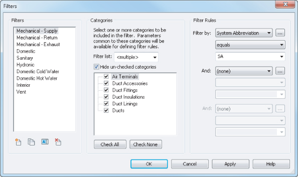
Figure 16.9 Using filters to override the graphic display
Using Mechanical Joint Fittings
So what do you do if you require special fittings? It's quite common to see mechanical joints required on fire protection systems. Because they do not exist in the out-of-box content of Revit MEP 2013, you are stuck with three choices:
- First, you can use regular fittings and then copy and rename them to the type of fittings you need, as was demonstrated for the fire pump. Then you can use schedules to count the number and make of the fittings.
- Second, you could create your own custom fittings. This requires that you have enough time and money to create every fitting you need. If you can afford it, this option is worth the investment in the long haul.
- Third is to find a manufacturer that has already developed their content. Victaulic has most, if not all, of their products in Revit on its website at www.victaulic.com. You can download them and load the fittings you need for your layout. No matter the source of your content, always take the time to test it to ensure that it works the way it should. Manufacturers that are starting to produce Revit content are looking to the industry for guidance. If you find something that doesn't work, let the manufacturer know.
Fire Protection Pipe Settings and Routing
Now you are nearly ready to route piping. There are still a number of pipe settings that will help you. Pipe Systems and Pipe Types settings will be important to adjust. Pipe material, the pipe sizing table, and the fluids table can also be altered as needed. These were explained previously in Chapter 11.
The various options for automatic and manual pipe routing were also discussed in Chapter 11. Unlike mechanical piping or domestic and sanitary piping, automatic pipe routing is more likely to be a productive option. Fire protection piping is often much more symmetrical than piping in other disciplines, making the autorouting easier to manage. Refer to Chapter 11 to review both auto and manual pipe routing.
The Bottom Line
Place fire protection equipment.
When starting a fire protection model, placing the equipment can make or break your design. The ability of Revit to verify your layouts early through the coordination of this equipment with other disciplines can set the pace for a successful project.
Master It
What method can be used to help speed up production when using a standard fire riser on multiple buildings?
Create fire protection systems.
Creating proper fire protection systems is essential to the performance and behavior of the fire protection model. Properly created fire protection systems also help with being able to coordinate with other disciplines during design.
Master It
Marty has just created a piping system called Fire Protection and for the System Abbreviation he used FP. He has created a filter set to System Abbreviation equals FP. Now Marty is in a presentation, and his system is not filtering properly. What should he check?
Route fire protection piping.
Fire protection piping can be routed by a couple of methods. It can be set up with different materials to help with takeoffs and specifications. Once piping has been routed, it can be coordinated with other disciplines to reduce errors and omissions.
Master It
What are some of the methods to deal with fittings that may not be supplied with Revit MEP 2013?