
Chapter 22
Details
With all the emphasis on using the Autodesk® Revit® platform as a design tool, it is easy to assume that it is weak when it comes to traditional drafting. Your projects do not need to be modeled to the smallest level of detail just because they can be. Many of the details that are used to convey design intent with a traditional 2D drafting method can also be used on a Revit project. In fact, it is best to keep your model as simple as possible and handle the more detailed information with, well, details.
The transition to Revit can be difficult, because it may seem that you will have to abandon all the details you have accumulated over the years. With Revit, you are able to use the CAD details you have in their native format directly in your projects, or you can easily convert them to Revit format and begin to re-create your library. Actually, Revit provides you with an opportunity to update and organize your library of details.
Using the tools available in Revit MEP 2013 for details and diagrams will enable you to create a complete set of construction documents.
In this chapter, you will learn to do the following:
- Use Revit drafting and detailing tools efficiently
- Use CAD details in Revit projects
- Build a Revit detail library
- Create detail views of your Revit model
Drafting and Detailing Tools
Whether you are embellishing a model view or creating a detail or diagram on a drafting view, the features of the Annotate tab provide you with the necessary drafting tools to generate line work, patterns, and symbols. The Detail Line button enables you to draw line work that is specific to the view in which it is created.
When you click the Detail Line button, the Modify | Place Detail Lines contextual tab appears on the ribbon. This tab is very much like the Modify tab, but it also contains the Draw panel, which allows you to select from an assortment of line tools to create either lines or shapes.
The Line Style panel lets you choose the type of line that will be used.
Line Styles
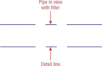
Line styles are an important part of your Revit projects because you can create styles that match the line patterns used for model components. This allows you to maintain a consistent look throughout your construction documents without having to override the graphic representation of each line. For example, you can create a style to be used for lines that represent Domestic Cold Water Pipe with the same line pattern used in a view filter that applies to the actual Domestic Cold Water Pipe or that matches the Graphic Overrides settings for a Domestic Cold Water system, as shown in Figure 22.1.
Figure 22.1 Line style matching model display
It may be helpful to think of line styles as family types for lines. You can draw a line with any line style and switch it to another style by using the selector drop-down on the Line Style panel of the contextual tab that appears when a line is selected. This gives you the freedom to draw a detail or diagram with one line style, focusing on the content of what is being drawn. You can then go back and change selected lines to more-appropriate line styles if necessary.
Regions
Filled regions are areas with a chosen pattern that can be used to represent a material or designated area of a detail. When you create a filled region, you can choose a line style for the border of the region. When you are drawing a detail that requires a filled region, determine how its boundaries will interact with the rest of the detail and choose appropriate border lines. Using the borders of a filled region requires less line work to be drawn because there is no need to have a line drawn over the border of a filled region.
Figure 22.2 shows a detail of a concrete floor penetration. A filled region is used to represent the concrete floor. The border lines of the region where the electrical box penetrates the floor are thicker than the rest. This is done so that additional lines do not have to be drawn to represent the box.
Figure 22.2 Filled region in a detail
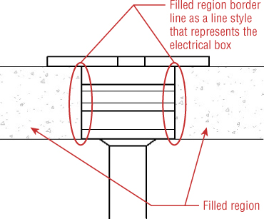
Notice that at the outer edges of the filled region, no border lines are shown. You can use the Invisible Lines line style for borders of a filled region that you do not want to show. This is also useful for when you have two filled regions that are adjacent. One region can define the line of the detail, while the overlapping region border can be set to invisible. This is necessary only if the overlapping lines cause the detail to look incorrect.
To draw a filled region, do the following:
When you have a filled region that overlaps other detail lines, you can select the region and use the Bring To Front or Send To Back button on the Arrange panel of the contextual tab to change the draw order. If the region is defined as having an opaque background, it will mask out any line work behind it as long as the view is set to the Hidden Line model graphics style. Annotation objects will not be masked by a filled region unless the region is a solid fill that is the same color as the text or annotation and the text style is set to transparent. A Wireframe view will cause any line work behind a region to be displayed, unless the region is a solid fill.
You can use two types of patterns for filled regions. Drafting patterns will change with the scale of the view, while model patterns are sized based on the dimensions in the model. To create a filled region pattern, click the Additional Settings button on the Manage tab and select Fill Patterns. Choose whether you want to create a drafting or model pattern at the bottom of the Fill Patterns dialog box. Click the New button to create a pattern. You can choose between parallel lines or crosshatched lines, setting the angle and spacing of the lines for a simple pattern. If you choose the Custom option in the New Pattern dialog box, you can import a PAT file, as shown in Figure 22.3.
Figure 22.3 Custom pattern for filled region
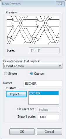
Once you create a custom pattern, you must reimport it to change the scale. You can set the Orientation In Host Layers setting for a pattern when it is used as a cut pattern for objects such as walls, floors, and roofs. You can choose to keep the pattern aligned with the element, orient the pattern to the view, or keep it readable. These settings are described here:
Aligned With Element
This option causes the pattern to maintain its relationship to the host.
Orient To View
This option causes all patterns to have the same alignment.
Keep Readable
This option causes the pattern to behave in the same manner as text. The pattern will maintain its alignment until it is rotated past 90 degrees, where it will flip to keep its intended alignment.
These settings do not have any effect on filled regions that are drawn manually.
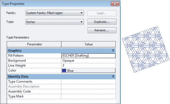
Once you have a pattern, you can assign it to a filled region style. Select a filled region, and click the Edit Type button in the Properties palette to edit a style or create a new one. Click the Duplicate button to create a new style, giving it a name that clearly defines what it is. It is usually best to name a filled region style with the same name as the pattern it uses. Click the Fill Pattern parameter to select a pattern used for the style. Other parameters allow you to set the transparency of the background, the line weight, and the color of the lines. These settings are for the pattern used by the style, not for the lines that define the border, as shown in Figure 22.4.
Figure 22.4 Filled region style settings
Another type of region you can use in details is a masking region. A masking region is a shape that will mask out any line work behind it. It is essentially a blank filled region. Masking regions will block out any model elements, detail lines, or filled regions in a detail view that is set to the Hidden Line visual style. The tools for creating a masking region are exactly the same as for a filled region. These regions are very useful when creating a detail that displays model elements that may contain elements that you do not want to be seen in the detail. You can use the border lines of a masking region to define portions of a detail in the same manner as with filled regions.
Similar to filled regions, masking regions mask out items only when the view is set to Hidden Line. Annotation objects are not masked by masking regions.
Detail Components
Many items within details are used repeatedly from one detail to the next. It can be tedious and time consuming to locate a detail that contains a specific item that you know you have drawn previously so that you can use it in a detail you are currently drawing. Detail components are special families that can be used to represent objects commonly used in details, saving you repetitive drawing time. When you install Revit MEP 2013 and its content, a Detail Items folder is included in the content library. The families in this folder are sorted by their construction-specification category. Each folder contains families that you can use in your details to save the time it would take to draw them repeatedly. Many of the families have multiple versions, each of which is drawn from a different viewpoint so that they can be used in section detail views.
Detail component families are different from annotation families because their size is not dependent on the scale of the view in which they are drawn. They are representations of building components drawn at their actual size. These items can be used when the building model has not been modeled to a level of detail to include the actual items. Certain architectural and structural elements do not need to be included in their respective models in order for these disciplines to achieve their project goals. When you create a section or callout of the model for a detail, you will need to include detail components for a true representation of the design.
It is a common practice to use generic styles for elements such as walls, floors, or roofs so as not to weigh down the model with unnecessary detail that can be handled with detail views. For example, although an exterior wall may have an outer layer of brick, the wall can be modeled generically, and detail components can be used in a detail view to show the brick layer. Detail components are useful for MEP discipline details as well. Many structural member components are available in the library. Items such as angles, beams, and channels can be quickly and accurately represented when creating a detail. Figure 22.5 shows an example of detail components used to create a detail.
Figure 22.5 Sample detail using detail components
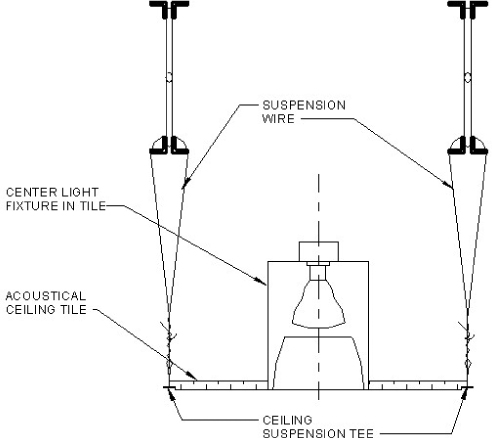
Even though the lighting fixture shown in the detail was included in the model, a detail component of a section view of a light fixture was used in the detail because the actual model component used was a simple cylinder. Every item shown in Figure 22.5 is a detail component family except for the centerline and annotations.
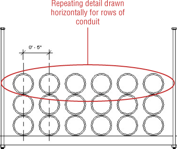
You can use detail component families to create repeating detail component styles. Repeating detail components allow you to quickly represent repetitive instances of components such as brick, glass block, or roof decking. They can also be used for MEP items such as pipe or conduit, as shown in Figure 22.6. In this example, the repeating detail was drawn horizontally to represent the rows of conduit.
Figure 22.6 Repeating detail for conduit rack
To create a repeating detail component style, click the Component button on the Annotate tab and select the Repeating Detail Component option. Click the Edit Type button in the Properties palette, and click the Duplicate button in the Type Properties dialog box. Name your style so that it can be easily identified for its use. Figure 22.7 shows the Type Properties dialog box for a repeating detail.
Figure 22.7 Repeating detail properties
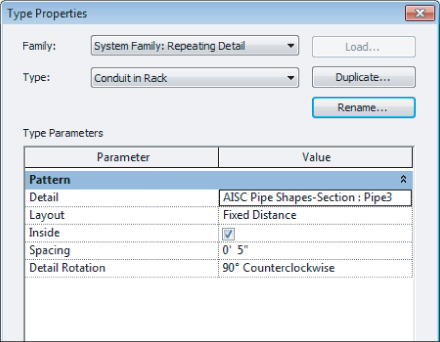
The Detail parameter allows you to select a detail component family that is loaded into your project for the repeating detail.
There are four choices for the Layout parameter settings:
Fill Available Space
This option places as many instances of the detail component that will fit within the length of the path drawn for the repeating detail.
Fixed Distance
This option can be used with the Spacing parameter, which defines the distance between each instance of the detail component. The number of detail components with the spacing that completely fit within the length of the path will display.
Fixed Number
This option equally spaces the detail component along the length of the path drawn.
Maximum Spacing
This option allows you to set the maximum distance between instances of the detail component. When the Maximum Spacing option is used, the space between instances may be less than specified depending on the length of the path. This ensures that a complete instance will occur at each end of the path. Additional instances are added as the path length causes the maximum spacing to be reached.
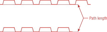
The Inside parameter determines whether the first and last instance of the detail fits within the length of the path drawn. The insertion point of the detail component determines the placement of the first and last instances. Figure 22.8 shows two repeating details with the same settings except that the top row's Inside parameter is set to No, and the bottom row's is set to Yes. Notice that the bottom row has fewer instances of the detail component even though the path distance is the same.
Figure 22.8 Repeating details
You can use the Detail Rotation parameter to rotate the detail component family so that it follows the path in the proper manner.
Because repeating detail components are system families, you cannot store them in your library, but you can create them in your project template for use on every project. Another alternative is to create a project file with all the styles you use and then transfer them into your projects as needed. The detail component families used in the repeating detail styles will be transferred along with the styles.
CAD Details
One of the primary benefits of a CAD application is the ability to save and reuse drawings. Because of this, most companies have spent years accumulating a vast array of CAD details. Making the transition to Revit does not mean that you can no longer use your library of CAD details. You can use CAD details and diagrams in your Revit projects, or you can re-create them in Revit format to build a new library of details for use on your projects. Converting your details to Revit reduces the number of CAD files you will have to link into your projects, which will help improve performance.
The key to success when using CAD details in a Revit project is to link the CAD file. If you have any concern for standards and for file performance, do not import CAD files into your project. It can be tempting to import a CAD file, explode it, and then clean it up for use in your project. Although this might provide immediate results, it can have an overall negative effect on your project. When you explode an imported CAD file, text and line styles are created for each unique text style and layer within the CAD file. The more of these unnecessary styles that you bring into your project, the poorer your file performance will be. It also opens the door for deviation from standards, because nonstandard text styles and line patterns will be available for use in other areas of the project.
If your project contains line patterns that have come from imported CAD files, you can remove them to avoid improper use. The line patterns show up as IMPORT- patterns in the Line Patterns dialog box, as shown in Figure 22.9.
Figure 22.9 Imported line patterns
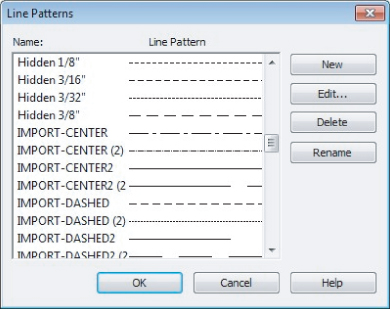
You cannot remove them using the Purge Unused tool, but you can remove them manually from the project in the Line Patterns dialog box.
When you link a CAD detail into your project, it may not look exactly as it does in CAD. Variations in text styles from CAD to Revit can cause undesired display of text notes and leaders. CAD details can be easily converted to Revit format, which enables you to display the detail correctly. Prior to linking a CAD file, it is best to open the file with its native application and set the text styles to match the text settings in your Revit project. Having the text defined the same way in both files ensures proper formatting.
Using Drafting Views
CAD details or diagrams can be linked directly onto a sheet in your Revit projects. If you intend to convert a detail to Revit format, however, it is best to link it into a drafting view instead of onto a sheet. This allows you to save the view as a file for use on future projects.
Even if you are going to use CAD details in your project without converting them, linking them into drafting views will help keep your project organized. Drafting views can be organized in the Project Browser, which will help you keep track of what details exist in your project. You can specify the properties of drafting views to group them into their appropriate locations within the Project Browser for easy access and management.
It is best to set the scale of a drafting view that is used for linked CAD details to the same scale in which the details are drawn. This will ensure accurate display of annotative objects within the CAD details.
Converting Details
When you link a CAD detail into a drafting view by clicking the Link CAD button on the Insert tab, you have some options for its display. One of the choices is for the colors of the CAD lines. Many people use colors in CAD to determine the line weight of printed lines. Choosing the Preserve option in the Link CAD Formats dialog box will maintain the colors of the line work when inserted into Revit, as shown in Figure 22.10. This will help you to determine what Revit line styles to use when converting the detail.
Figure 22.10 Color options for a linked CAD file

There are a few ways to convert a CAD detail into Revit format. The most time-consuming and least desirable method is to import the CAD file, explode it, and convert the line and text styles to Revit lines and text. This should not be done directly in your project but rather in a separate file in order to keep the imported styles from populating your project. The file should then be purged of all unused styles before being saved to a library or used in projects.
The easiest method for converting CAD details to Revit format is to link the file into a drafting view and trace the line work. Although tracing seems like a tedious task, there is a drafting tool that expedites the process. With a file linked into a drafting view, click the Detail Line button on the Annotate tab. On the Draw panel, select the Pick Lines tool, as shown in Figure 22.11.
Figure 22.11 The Pick Lines drafting tool
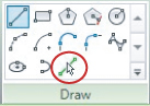
The Pick Lines tool allows you to select lines within the CAD file, and it will place a Revit line in the same location that matches the selected line. With this tool, you can pick the lines of a CAD detail and have a Revit version within a short period of time.
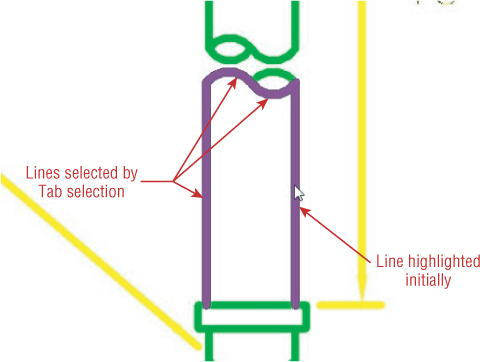
You cannot use the window-selection feature to select the lines. Each line must be selected individually. However, when you combine this tool with the Tab selection functionality of Revit, you will save time and reduce the number of clicks. Placing your cursor over a desired line and pressing the Tab key on your keyboard will highlight any lines connected to the line under your cursor, as shown in Figure 22.12. With the multiple lines highlighted, you can click to select them, which will place a Revit line at each location.
Figure 22.12 Tab selection of multiple lines
When you are using the Pick Lines tool to convert a CAD detail, you may want to choose a line style that is thicker than the lines being copied. This will help you keep track of which lines have already been converted, especially if your CAD detail is drawn with black lines. As you click to draw Revit lines, a padlock icon will display and allow you to lock the line to the CAD detail line. This is unnecessary, because the CAD detail will be removed. Once you have completed the line conversion, you can select lines and change their style to match the intent of the detail. Using this process is more efficient than constantly switching between line styles while converting the detail.
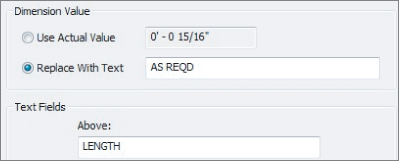
You cannot use the Pick Lines tool to copy the text within a CAD detail, so you will have to place notes and dimensions manually. Use the ability to override dimension text when necessary for details that are not drawn to scale. You will have to create any required filled regions manually as well.
Once a CAD detail has been converted to Revit format, you can use the Manage Links tool to remove the linked CAD file or simply select the linked CAD graphics and delete them, leaving you with a native Revit detail that can be saved to a detail library for future use.
Reducing your reliance on linked CAD files is an important step toward reducing project load times, view regeneration, and other causes of poor file performance. Because details are such an important part of any project, having Revit details available for use is crucial to the success of a project. Now that you have learned some options for converting a CAD detail, practice by completing the following exercise:
Figure 22.13 New Drafting View dialog box
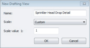
Figure 22.14 Linked CAD file options
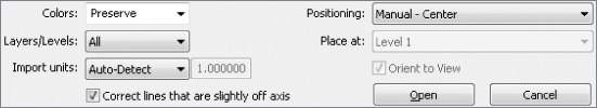
Figure 22.15 Line Style ribbon panel
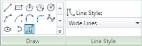
Figure 22.16 Tab selection of multiple lines using the Pick Lines tool
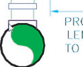
Figure 22.17 Arc selection
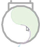
Figure 22.18 Dimension text override
Strategies for Creating a Detail Library
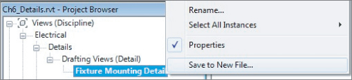
When you right-click a drafting view in the Project Browser, one of the menu options is Save To New File, as shown in Figure 22.19.
Figure 22.19 Drafting view context menu
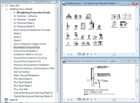
Saving a drafting view as a file allows you to put it in a location where you can build a library of details and diagrams that can be accessed for use on other projects. You can organize your detail library in any manner that suits your workflow or processes. One option is to create a drafting view that has several common details on it. The view is then saved as a file, and the file is opened. Within this new file, the drafting view is duplicated and a new drafting view for each detail is created, leaving you with a single file containing multiple drafting views, each with its own unique detail. This will make it easy to locate specific details or allow you to place an entire group of details into your project. Figure 22.20 shows an example of a detail file containing multiple drafting views for individual details.
Figure 22.20 Sample detail file organization
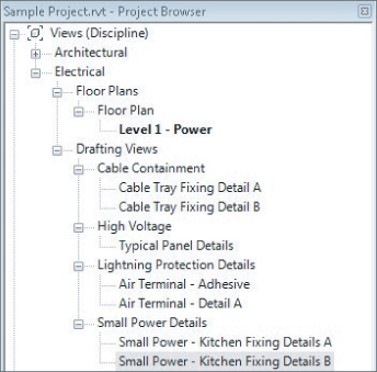
When you create a drafting view for each detail, you can easily bring the detail into your project, without having to load a drafting view or an entire set of details. This will reduce the number of views in your project, making the Project Browser more navigable and keeping your project file size minimized. Figure 22.21 shows a sample Project Browser organization for detail views.
Figure 22.21 Sample detail view organization
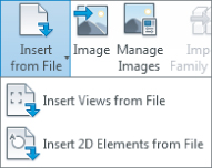
You have two choices for inserting details with the Insert From File button located on the Insert tab and shown in Figure 22.22. They are Insert Views From File and Insert 2D Elements From File. Each option is explained in the following sections.
Figure 22.22 Insert From File options
Inserting 2D Elements
The Insert 2D Elements From File option allows you to bring in a detail without having to load the drafting view into your project. This is the preferred method if you have created a separate drafting view for each detail. When you choose this option, a dialog box appears for you to browse to the file containing the detail. When you open the file, the Insert 2D Elements dialog box appears, as shown in Figure 22.23.
Figure 22.23 Insert 2D Elements dialog box
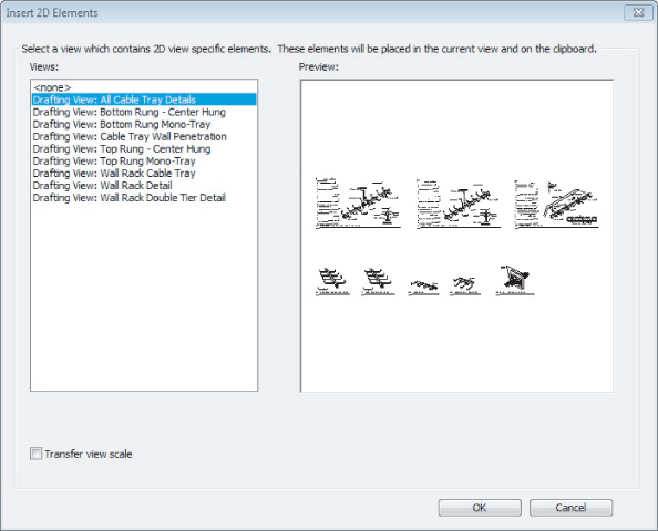
In this dialog box, you can select the view that contains the detail you want to place into your project. When you click OK to load the detail, you may get a dialog box alerting you to duplicate types within the detail file and your project file. The types defined in your project will be used. When you click OK, the detail is ready for placement in the current view of your project.
You should begin this process with a drafting view open in your drawing area. Because the detail is coming from a drafting view, you cannot place it directly onto a sheet by using this process. To get the detail onto a sheet, the detail must first be placed onto a drafting view, and then the view can be placed onto a sheet.
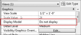
These elements can also be pasted into a callout view of a plan or section so that the detail relates directly to the model. In the properties of the view, the Display Model parameter can be set to Do Not Display, as shown in Figure 22.24.
Figure 22.24 Display Model parameter setting
When the detail is placed into your drafting view, it is just as if you drew the detail manually in the view. You can edit the lines and text if necessary to modify the detail for your specific project. If you change the detail significantly enough that you want to keep it as a new detail, you can copy and paste it into a new drafting view in the detail file where it came from.
Inserting Views
The Insert Views From File option will load selected views from a chosen file. You should use this method if you want to have the drafting view in your project. Choosing this option brings up a dialog box where you can browse to the file containing the view you want to load. This does not have to be a file located in your detail library. For example, if you know of a drafting view in another project that has details on it that you want for your project, you can browse to that project file and choose the drafting view from it.
The Insert Views dialog box that appears when you open a file shows any views available for loading into your project. You can select multiple views, including drafting views, schedules, and reports to be added to your project. The Preview Selection option in the lower-left corner enables you to see the entire contents of the view prior to loading it. When you click OK in this dialog box, you may get another dialog box indicating that there are duplicate types between the file and your project and that your project types will be used. When you click OK, the selected views will be added to your project. The views will appear in the Project Browser based on their properties and your browser organization, so it is a good idea to give your detail library files the same view properties that you use in your projects. This will make the views easy to locate when they are inserted and will save you time in organizing your Project Browser.
Model Detail Views
Many project details are independent drawings that represent the construction of a component, but some details are taken from the design to further enhance the level of information given in plan, section, or elevation views. Details are often used to convey the installation of components rather than just to provide information about the component. It is important to a coordinated design to be able to convey the intent of placement of building objects and their relationship with other components.
You can use detail views in your projects to provide additional information about the model that is not part of the model as a whole. For example, you may have a pipe being run in the space of a column wrap at several locations throughout the model. You may choose to show this one time in a detail view and then denote where it occurs in each floor plan, instead of modeling it at each occurrence. Unlike drafting views, detail views allow you to show model elements. Using detail views can help you provide the necessary level of information for the project without weighing down the model and spending time on repetitive modeling tasks.
Plan Callouts
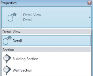
The Callout tool on the View tab is one way to create a detail view from an area of your model. When you click the Callout button, you can choose from the Type Selector in the Properties palette what type of callout to create: either a Floor Plan callout that is used for enlarged plans or, to isolate a specific area of a plan, a Detail callout that creates a detail view.
Detail views are unique types of views in Revit. They have properties similar to plan, section, and elevation views, but they also have settings specific to the area of the model being shown. Detail views will take on the discipline of the view in which they are drawn. The Show In Parameter option allows you to display the callout in the parent view only, which is the view where the callout is initially drawn, or in any intersecting views, which means the callout will display in any views that show the area of the plan from which the callout is taken. Unlike a regular floor plan view, you cannot adjust the View Range settings of a detail view.
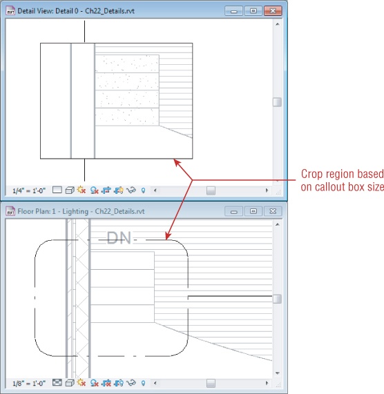
A detail view will show the portion of the model within the boundaries of the callout box. This box determines the crop region within the detail view, as shown in Figure 22.25.
Figure 22.25 Callout box and crop region
A detail view taken from the plan, elevation, or section will show any grid lines or levels whose 3D extents cross within the boundaries of the callout to help with location information. These datum annotation elements can be turned off if necessary, but you cannot edit them in a detail view. They will move to maintain their relationship to the crop region when the crop region is adjusted.
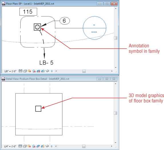
When you create a detail view of a floor plan area that contains objects represented by nested annotation symbols, the annotation symbols will not display in the detail view. This may require you to set the visibility of the actual model graphics in your families so that they can be seen at certain Detail Level settings. Figure 22.26 shows a floor box in plan view and the detail view of the same location. Notice that the annotation symbol does not show in the detail view, but the actual floor box is shown because the Detail Level of the detail view is set to Fine.
Figure 22.26 Detail view
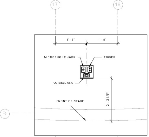
The main purpose of a detail view is to see a specific portion of the model and then add detail lines, regions, and other annotation objects to provide additional information about the design. Once a detail view has been created, you can use the same drafting tools as used in a drafting view to embellish the model information shown in the view. Filled regions can be added to show materials that may not be shown on the actual model objects. Masking regions can be used to block out items that you do not want to show in the detail. Figure 22.27 shows how you can add to the detail view of the floor box in order to provide more information about the object and its location.
Figure 22.27 Detail view with added information
If you already have a detail drawn and you want to call out an object or an area of your model and reference that detail, you can use the option to reference another view. This option appears on the Options Bar when you click the Callout button on the View tab, as shown in Figure 22.28.
Figure 22.28 Options Bar setting for referencing another view
This will associate the callout with the view selected in the drop-down list next to the Reference Other View option instead of creating a new detail view. This option is useful for details that occur in multiple locations throughout a project. Instead of creating a new detail view for each occurrence, you can create one and then reference that view in every location required on your plans. When you delete a callout that references another view from a model view, the referenced view will remain in your project. With this functionality, you can combine your library of drafting details and callouts to convey design intent in a manner that is easily managed and coordinated.
Section Callouts
Another method for creating a detail view is to create a section view of an area of the model. One of the types of section views that can be created is a detail view, as shown in Figure 22.29. This type of section is created in the same way as a building section, but the view created is a detail view instead of a model section view.
Figure 22.29 Section view types
Creating section detail views allows you to show project information without having to model elements that you ordinarily would not model to show in plan views. The same drafting tools used in drafting views can be used to provide additional information to the view in order to convey design conditions without having to add model components.
Section detail views can reference other views in the same way as plan callout detail views. This allows you to create the detail drawing once and reference it as many times as needed in your project.
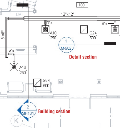
In some cases, you may be able to use a building section to convey more of the design intent without having to embellish the section with detail annotations. You can create different section tags to differentiate between model section and detail section marks in your views. Figure 22.30 shows how different section tags can be used for different types of sections. This will help you know what a section mark is used for when you come across it in a plan view. You can find the settings for section tags by clicking the Additional Settings button on the Manage tab.
Figure 22.30 Section marks for different types of views
The Bottom Line
Use Revit drafting and detailing tools efficiently.
Revit MEP 2013 has many tools for creating the details and diagrams needed to enhance your model and provide the necessary level of information for your projects.
Master It
Although the drafting tools in Revit MEP 2013 may be unfamiliar at first, learning to use them efficiently and effectively will help you spend more time focusing on design decisions instead of drafting efforts. Describe how filled regions can be used not only to display a pattern but also to provide line information in a detail.
Use CAD details in Revit projects.
Much of the detail information used in projects has already been drawn. When you transition to Revit, you can still use your CAD details.
Master It
Using CAD details in a Revit project can be a quick way to complete your construction documents in a timely manner. However, using many CAD files for details can have a negative effect on file performance, so it is important to link CAD files whenever they are used. Explain why importing and exploding CAD files can adversely affect your project.
Build a Revit detail library.
Having a library of details makes it easy to save time on projects by not having to spend time drawing details that have already been created.
Master It
Drafting views can be saved as individual files for use on projects as needed. True or false: A drafting view will be added to your project when you use the Insert 2D Graphics From View option of the Insert From File tool. Explain.
Create detail views of your Revit model.
Some details require the model to be shown in order to show installation or placement of objects.
Master It
Callout views can be created from plan, section, and elevation views. Explain how detail views are different from drafting views.