
Chapter 15
Plumbing (Domestic, Sanitary, and Other Piping)
Routing plumbing piping has come a long way from drawing circles and lines on paper. Over the past 30 years, tools such as the straight edge, 30/60 triangles, and the Timely template have been replaced by CAD systems. With more owners requiring BIM, a plumbing designer has to become a virtual pipe installer. Instead of just drawing circles and lines, you have to understand more about how fittings go together to construct your piping design. This is where Autodesk® Revit® MEP excels; it can help you create your designs more accurately and efficiently. But make no mistake, now more than ever before, you should plan accordingly for your plumbing projects. What are the BIM goals for the project? What is the level of detail you will be targeting? Develop and document new workflows between you and the architect; create custom content; be much more dependent on the accuracy and any changes made by the architect. Those are just a few of the challenges you will be facing, and if you take the time to open the conversation with the architect and internally in your company, you will have accomplished the biggest challenge that people ignore when starting their first plumbing project—planning and setting the expectations!
In this chapter, you will learn to do the following:
- Customize out-of-the-box Revit plumbing fixtures for scheduling purposes
- Use custom plumbing pipe assemblies to increase speed and efficiency in plumbing layouts
- Adjust the plumbing pipe settings
- Select the best pipe routing options for your project
- Adjust pipe fittings
- Adjust the visibility of pipes
Configuring the Plumbing Views
One of the most important parts of a successful plumbing project is configuring the views settings. Many companies have tried the plumbing portion of Revit in their early stage of the Revit implementation, and most of them walked away from it saying, “It's not ready yet.” Without the proper configuration of the settings it will never be ready for your company either.
Global Settings and Views Specific Settings
There are several settings that should be adjusted so your pipes are properly displayed. The following list is certainly not exclusive but should point you in the right direction and show what to pay attention to when setting up your plumbing sheets:
- All plotted views should be set to Hidden Line.
- Detail Level should be set to Coarse.
- View range should be adjusted to display necessary pipe systems.
- Visibility Graphics categories should be set to display the appropriate object categories. Note: It is more efficient to turn off other disciplines' objects by using worksets instead of managing every single object. However, good work-sharing practices must be in place, and all objects must be associated with the appropriate workset.
- Pipes going under plumbing fixtures will be completely hidden. To resolve this, plumbing fixtures should be set to transparent for your model and any linked Revit models containing plumbing fixtures. Note: Plumbing fixtures with a high detail level may start displaying unnecessary lines.
- Wall cut patterns should be turned off. For example, very often architects assign cut patterns for their walls to display the fire rating. While this is not important for the mechanical or electrical plans, it is crucial for the plumbing plans, where most objects are in the wall (see Figure 15.1).
- Pipe Rise/Drop Annotation Size under Mechanical Settings should be changed. Note: 7/128″ is a good starting point.
- For buildings that are not orthogonally oriented, scope boxes should be set up and associated with the views. Another, simpler method is to rotate the crop region so you can lay out your pipes orthogonally to your screen.
- Configure the Single Line gap under the Mechanical Settings to match your company standard. Note: 3/128″ is a good starting point.
Figure 15.1 Turning off wall cut patterns
Defining Systems Visibility through Filters
Starting with Revit MEP 2012, Revit automatically creates the piping systems for you when you lay out pipes, even when pipes are not connected to plumbing fixtures. When drawing pipes you will need to specify what system type it belongs to. The system type will define the lineweight, linetype, color, and System Abbreviation. The System Abbreviation can be used to define what system will appear on what sheet via filters. This will help you hide the mechanical pipes in the plumbing views.
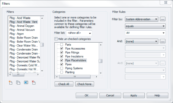
Establishing a good naming convention for the filters is very important, because that defines the order in which you see them in your Properties palette when drawing pipes. The default examples of filters and their settings are not going to get you too far with your projects. I recommend that you take your time and come up with a complete list of systems that your company uses and create them as system types and filters in Revit MEP. Organizing all of them in Excel can be very beneficial! (See Figure 15.2.) Notice that the Filter By setting is set to Equals the System Abbreviation. Note: The parameter System Abbreviation was not available prior to Revit MEP 2012, and the settings would be different for those projects and templates.
Figure 15.2 Sample filters and their settings
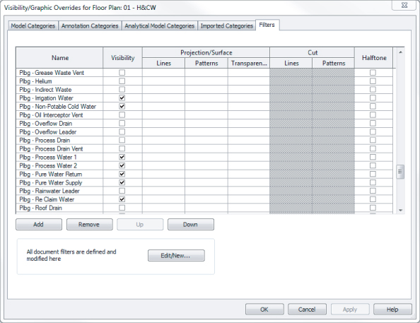
Once the filters have been created, go into each view where you want the different disciplines to show up and type VG to bring up the Visibility/Graphic Overrides dialog box. Click the Filters tab, and add the newly created filters. Using the Visibility check boxes under the Filter tab, you can define the systems that would be visible in that view. In the past filters were used to also define color, line patterns, and in some cases line weights. Since Revit MEP 2012, the recommended place to control those is in the system type. This way those settings will be global rather than per view. However, the filters will still be managed and control what system is visible in what view (see Figure 15.3).
Figure 15.3 Adjusting the Visibility of pipe and duct systems through Filters
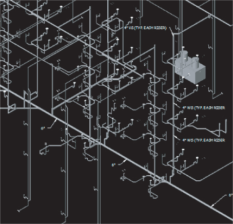
Now that your plans are coordinated and displaying the way you require, you are well on your way to completing your documentation. Consider using the same filters to display 3D views that can enhance the design, making it easier to understand and further reducing errors.
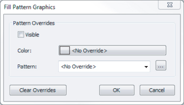
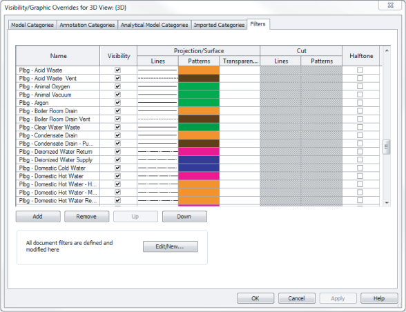
Every rule has its exception, and here is a great example for it. Controlling the colors and line patterns of your systems in the 3D views would color the contour of the pipes, making the pipes hard to see. Instead of going that route, I suggest you override those in the filters with a solid pattern; this way your 3D views will be a lot easier to see and understand (see Figure 15.4).
Figure 15.4 Applying filter overrides for 3D views
One common drafting standard is to show all piping serving a given floor in the same view. For instance, on the sheet showing the restroom located on the second floor of a three-story building, you would expect to see all the sanitary piping below the second floor and the vent piping in the second-floor attic serving that restroom. You would not want to see the sanitary pipe serving the third-floor restroom, even though it also occupies the second-floor attic, and you would not want to see the vent piping serving the first floor.
One way to accomplish this selective visibility in projects with overlapping view ranges is with workset visibility. You can assign all the piping serving the first, second, and third floors to specific first-, second-, and third-floor worksets. This will allow you to turn off the first- and third-floor worksets, cleaning up your second-floor view. See Chapter 3, “Worksets and Worksharing,” for more information.
Working with Plumbing Fixtures
Plumbing fixtures are as important to the look of an architectural design as granite countertops or marble tile. Plumbing fixtures, when properly selected, will not only enhance the visual design but will also promote cleanliness and hygiene. Plumbing fixtures normally are placed by the architect during schematic design to coordinate usability and meet the requirements of governing codes.
From a plumbing design point of view, different criteria must be examined. What are the water conservation guidelines? Are the plumbing fixtures required to meet LEED standards? Other questions should be asked during design: Will you as the designer want to use the same plumbing fixtures that the architect's model uses to connect to your piping, or will you substitute your company's standard fixtures? If so, do you need to apply shared parameters that reflect the design standards required? For example, in the United States there are two major plumbing codes: the Uniform Plumbing Code and the International Plumbing Code. To complicate matters further, some states will adopt one of these two codes and then add their own amendments, creating their own state code.
With Revit MEP 2013, you can apply this information through the use of parameters. This can be done in a couple of ways. First, you can edit the information in the family itself by selecting a plumbing fixture family and editing the information through the Type Properties dialog box (see Figure 15.5).
Figure 15.5 Editing the Type Properties
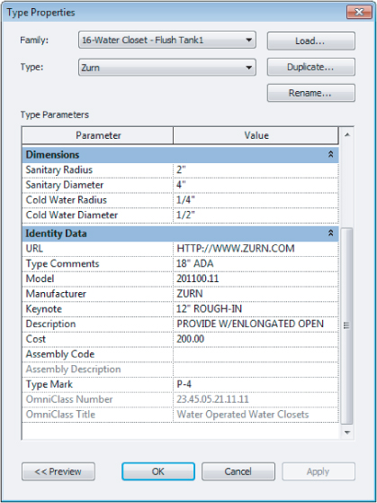
The second way to edit the information is to create a type catalog. Using type catalogs enables the user to easily produce more information about different types or models of the same family. For example, most bathroom manufacturers use model numbers to show the differences in finishes, rough-in locations, handle locations, and handicap accessibility information. Also, type catalogs allow the plumbing design to be easily changed from one manufacturer to another.
The easiest way to create a type catalog is to first open a plumbing fixture family, and then review and make note of the type properties you want to be able to modify. Then create a TXT file that will populate the information. To create this TXT file, do the following:
| Keynote | Keynote##other## |
| Model | Model##other## |
| Manufacturer | Manufacturer##other## |
| Type Comments | Type Comments##other## |
| URL | URL##other## |
| Description | Description##other## |
Figure 15.6 Creating a CSV file for type catalogs
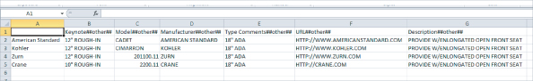
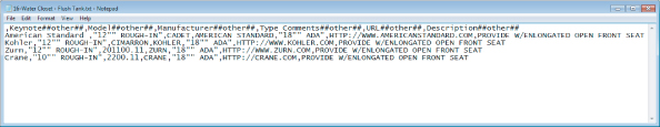
Figure 15.7 Opening the TXT file in Notepad
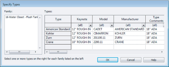
If you created your file properly, you should see a catalog of information when inserting the family (see Figure 15.8).
Text
parameter name##OTHER##
Integer
parameter name##OTHER##
Number
parameter name##OTHER##
Length
parameter name##LENGTH##FEET
Area
parameter name##AREA##SQUARE_FEET
Volume
parameter name##VOLUME##CUBIC_FEET
Angle
parameter name##ANGLE##DEGREES
Slope
parameter name##SLOPE##SLOPE_DEGREES
Currency
parameter name##CURRENCY##
URL
parameter name##OTHER##
Material
parameter name##OTHER##
Yes/No
parameter name##OTHER##
<Family Type>
parameter name##OTHER##
Figure 15.8 Type catalog
Now that you have information added to your plumbing fixture family and you have placed the plumbing fixtures into the plan, you will want to schedule that information.
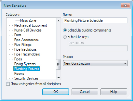
To accomplish this, go to the Analyze or View tab on the ribbon, and then select Schedule/Quantities. This opens the New Schedule dialog box. Select Plumbing Fixtures from the Category group, and then click OK (see Figure 15.9).
Figure 15.9 Select Plumbing Fixtures from the Category group.
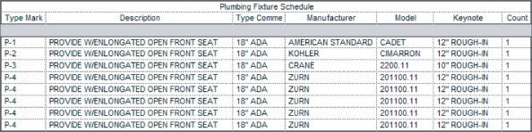
Next, select the information from the Available Fields dialog box and add it to the Schedule Fields (In Order) dialog box. Then click OK, which will create your schedule (see Figure 15.10).
Figure 15.10 Plumbing Fixture Schedule
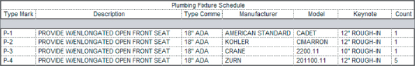
Now that you have the Plumbing Fixture Schedule created, you may not want to see duplicate information or blank information, so you will need to sort the information. To do this, go to the Properties palette, select Sorting/Grouping, change the Sort By option to Type Mark, and then deselect the Itemize Every Instance check box. Now your schedule will show only the items that have information (see Figure 15.11). For more information on customizing the appearance and content of schedules, see Chapter 7, “Schedules.”
Figure 15.11 Sorted schedule
Working with Architectural Linked-in Plumbing Models
When using Revit MEP for plumbing, there are two main options for coordinating plumbing fixtures between architectural linked-in models and plumbing models. The first option is to manually place the plumbing designer's edited plumbing fixtures over the architectural plumbing fixtures. The second option is to use the Copy/Monitor feature.
Using the Copy/Monitor feature will place either an exact copy of the architect's fixture family or allow you to select your family instead. This option allows you to use a family that has already been edited with proper connectors and scheduling information. When you are placing fully-modeled plumbing fixtures with connectors, you will need to turn off the architectural plumbing fixtures. Otherwise, any slight difference between graphical representation or location between your plumbing fixtures and the architectural plumbing fixtures will be a disaster for your final plot sheets. Using plumbing fixture assemblies or connector placeholders is more forgiving. In this case the architect is in control of the graphical representation of the plumbing fixtures, and you are in control of the plumbing fixture information and specifications.
With either method, you will have to take care that your fixtures remain coordinated with any architectural plan changes. If you have placed your families manually, you will have to check locations visually. If you have used the Copy/Monitor function, Revit will notify you that there has been a change via the Collaborate ribbon tab ⇒ Coordination Review. Also, the Copy/Monitor feature does not automatically update to show any new fixtures that the architect may have added. We'll talk more about this later in the chapter.
With either of the options, you can use plumbing fixture families that represent only the piping portion of each fixture. These custom pipe assemblies are fittings preassembled or modeled to line up in the locations of the linked architectural plumbing fixtures. These are created as plumbing fixture families.
Create Custom Pipe Assemblies
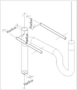
Custom pipe assemblies can be represented in one of two ways in the Family Editor. First, you can use sweeps to represent the p-trap, wye, and associated piping. This method creates a smaller file size and reduces the size of the overall plumbing model. Assemblies representing fittings with sweeps and extrusions would not allow you to schedule the fittings directly. However, if quantity takeoffs are important to you, they can be achieved by creating shared parameters that store the number and type of fittings that are used in the assembly (see Figure 15.12).
Figure 15.12 Representation of a pipe assembly created with sweeps
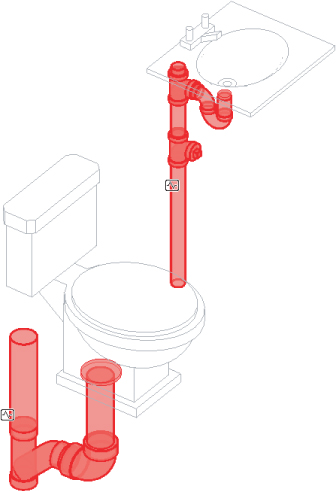
The second method is to assemble nested families, which can allow for better quantity takeoffs for all the fittings, create more-accurate dimensional information when supplied by manufacturers, and be easier for the plumbing designer to create. The downside is that it will produce a larger family file. This second option will help you achieve more of the building information modeling status while helping to increase productivity (see Figure 15.13).
Figure 15.13 Nested pipe assembly
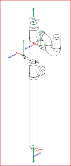
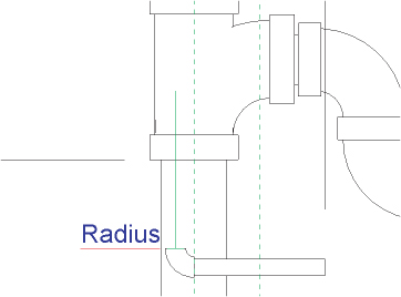
Now let's examine how nested piping assemblies are put together and some key areas to be mindful of:
Figure 15.14 Aligning, locking, and dimensioning to lock nested families down
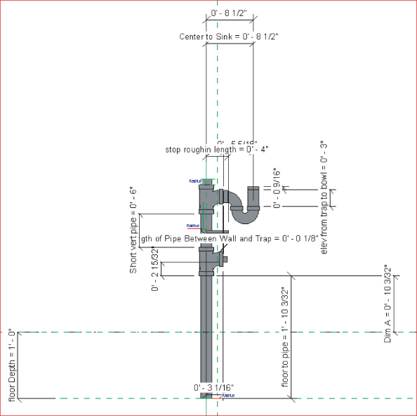
Figure 15.15 Using parameters to flex the piping assembly
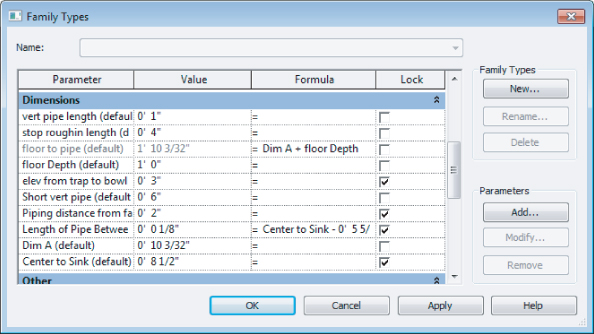
Figure 15.16 Adding a simple elbow pointed in the direction of flow
Now that you have reviewed some of the items that make up a pipe assembly, you can place the pipe assembly family in your plumbing model and align it with the architectural plumbing fixtures without having to turn them off. If the architect adds a plumbing fixture, you now have the capability to view the added fixture. By following this workflow, you can both tag and schedule the pipe assembly family while the graphic representation needs are satisfied by the family in the architectural link file.
Copy/Monitor Plumbing Fixtures
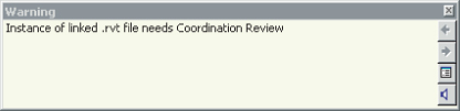
Now let's take it a step further. If the plumbing fixtures that the architects are using match the same orientation of your pipe assemblies, you can copy/monitor the pipe assemblies directly behind the plumbing fixtures. Then, when the architect moves a plumbing fixture, you will receive a warning that you need to coordinate your view (see Figure 15.17).
Figure 15.17 Coordination Review Warning
You will also have the capability to copy and change all of the plumbing fixtures on multiple levels at one time. This can be a huge time-saver.
To use Copy/Monitor, do the following:
Figure 15.18 Type Mapping
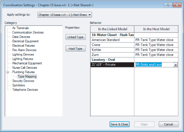
Figure 15.19 Copying and replacing fixture types
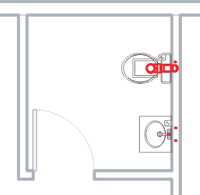
Figure 15.20 Monitoring symbol shown on the assembly
To take full advantage of the Copy/Monitor feature, you will need to coordinate all of your plumbing fixtures with your pipe assemblies, but you will find it is time well spent.
Choosing Pipe Settings and Pipe Routing Options
When setting up piping to route, you will want to apply the proper pipe material so that quantity takeoffs can be easily scheduled. Another reason to apply the appropriate pipe material and pipe fittings is to get the invert elevation for sloping systems. If the pipe material and fittings are incorrect, the invert elevation value will not be reliable. There are several areas you will have to adjust to set this up properly. Most important are the Piping Systems and Pipe Types settings. These and other piping parameters are discussed at length in Chapter 11, “Mechanical Piping.” Also covered in that chapter are the two routing options, autoroute and manual. Here you will examine the options available for sloped piping. One thing to note is that currently Revit doesn't come with no-hub fittings. There are some manufacturers making them, but be aware that they can really be over-detailed, and you may experience performance issues with your projects. As a start, using the PVC fittings that come with Revit MEP 2013 should produce reasonable graphical results.
Sloping Pipe
When modeling pipe, you can use either the autoroute or the manual routing feature. Especially when applied to sloped pipe, you are more likely to have success with a manual layout. Before you lay out your pipes, it is a good idea to check the Slopes settings located under Manage ⇒ MEP Settings ⇒ Mechanical Settings ⇒ Pipe Settings ⇒ Slopes. From here you will be able to add or delete slopes that would be available for you to use when drawing pipes.
For sloping pipe to work properly, it needs to have start and end points. To set up sloping pipe, open Ch15_plumbing.rvt and Ch15_base.rvt. Also download sanitary point of connection.rfa and wall cleanout.rfa. All of these files are found at www.sybex.com/go/masteringrevitmep2013. Next, do the following:
Figure 15.21 View Range settings
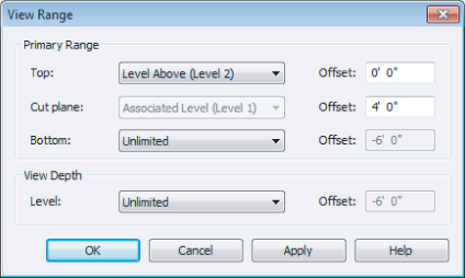
Figure 15.22 Recommended settings for drawing non sloping pipe layouts
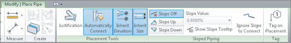
Figure 15.23 a) Inherit Elevation. b) Inherit Size.
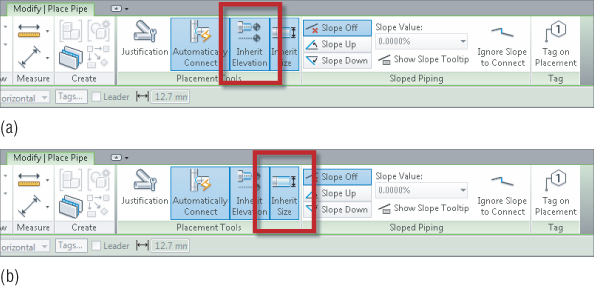
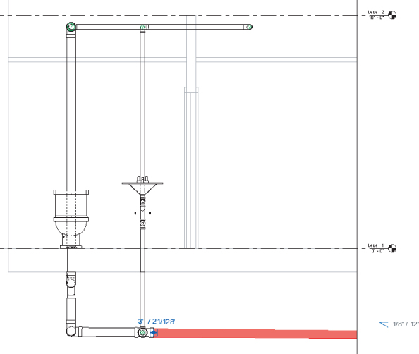
Figure 15.24 Sanitary layout with sloped piping
Annotating Invert Elevation and Slope
Once your piping model is at the desired slope and elevation, you can easily apply parametric elevation and slope annotations. Choose Annotate ⇒ Dimension ⇒ Spot Slope or Spot Elevation. The slope tag is very simple; it can be placed at any point along a pipe run, while viewing single- or double-line pipe.
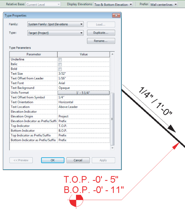
The elevation tag is more complicated. The Spot Elevation tag will be able to show only the top and/or bottom elevation of the pipe selected. You must be able to see double-line pipe (Fine Detail) in order to place the Spot Elevation tag. This tag exists only within the project. It is a system family, and it cannot be edited in the Family Editor. This means that all changes are done in the Properties and Type Properties palettes within the project interface. In the Options Bar, you will want to make sure to set the elevation to reference the correct level. Also in the Options Bar, you should set the Display Elevations option to either Bottom Elevation or Top And Bottom Elevation. In the Type Properties dialog box, you will likely want to change the Units Format and the Top and Bottom Indicators to match your standard for labeling pipe elevation, for example, B.O.P. = bottom of pipe (see Figure 15.25).
Figure 15.25 Customizing the Spot Elevation tag
If you prefer to annotate the elevation of the pipe centerline, you will have to use a pipe tag. This is the same type of annotation family as the common pipe diameter tag. You can duplicate and edit that family to change the label to include the parameters Start Offset and End Offset. Note that these parameters can display the elevations of only the two endpoints of each pipe segment. Like the Spot Elevation tag, they cannot display the elevation at any point along the pipe segment.
Using Fittings
Without fittings, piping would not be worth a whole lot. Fittings help shut off, regulate, open up, and, most important, save lives. In Revit, most fitting families have the following functions:
End Cap
These can be placed only at the end of pipe.
Tee, Tap, Wye, or Cross
These can be placed anywhere along pipe runs.
Transitions, Couplings, or Unions
These can be placed only at the end of pipe. They are used to join a smaller, larger, or same-size pipe.
Flange
These can be placed at the end of pipe or face to face with another flange.
Using Pipe Fitting Controls
Understanding pipe fitting controls can really make life easier if you are routing a lot of piping. When you are laying out your piping, turn 90 degrees to create an elbow. If you click the elbow, you will notice a plus (+) sign. If you click that sign, it will change from an elbow to a tee, allowing you to add more piping and to continue your pipe routing. If you select the minus (–) sign, it will downgrade the fitting. When you see the ![]() symbol on a fitting, it allows you to rotate the fitting, and the
symbol on a fitting, it allows you to rotate the fitting, and the ![]() symbol allows you to flip the fitting.
symbol allows you to flip the fitting.
Placing Valves
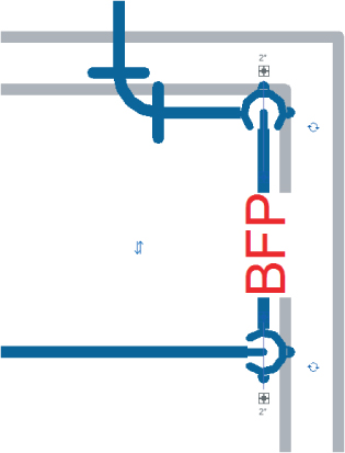
When you need to add valves to your piping, select the Home tab and click Pipe Accessories. Use the Type Selector to select the type and size of valve you want to use. Most valves will break into the piping and connect by simply selecting a piece of pipe (see Figure 15.26).
Figure 15.26 A fitting breaks into the piping system.
The Bottom Line
Customize out-of-the-box Revit plumbing fixtures for scheduling purposes.
Learning how to customize existing plumbing fixtures can help with productivity and provide more-robust building information.
Master It
When you are setting up your project/template views, where would you control the linetypes and colors from?
Use custom plumbing pipe assemblies to increase speed and efficiency in plumbing layouts.
Sometimes, you are required to think outside the box and learn how to use new tools to get the most benefit out of them. By utilizing the new Copy/Monitor feature when creating custom pipe assemblies, you can take production to the next level.
Master It
Why are nested pipe assembly families better to use than the modeled pipe assembly for a BIM project?
Adjust the plumbing pipe settings.
Pipe settings are crucial to the ability to have Revit MEP model your plumbing layout, the way it will look, and the way it will perform.
Master It
Do fitting parameters have to be set up in the system pipe types?
Select the best pipe routing options for your project.
When using Revit MEP 2013 for your plumbing layouts, you must understand the functions of automatic pipe routing, manual pipe routing, and sloping pipe. Once these functions are mastered, you can lay out any type of piping system.
Master It
A plumbing designer has just been asked to lay out a sloped plumbing system and has only a day to pipe up a clubhouse. Where should the designer start the pipe route?
Adjust pipe fittings.
Pipe fittings are needed in systems to make the systems function properly and to produce documentation for construction. Being able to add or modify fittings can increase productivity.
Master It
You have just finished your modeled layout and given it to your employer for review. Your boss asks you to remove a couple of elbows and replace them with tees for future expansion. What would be your method to accomplish this quickly?
Adjust the visibility of pipes.
Being able to adjust the visibility gives the plumbing designer or user the ability to set up multiple views and control the graphics for documentation.
Master It
There are too many systems showing up in your views. What would you do to show only one piping system in that view?