
Chapter 17
Solid Modeling
It may seem like being able to create solid models efficiently and effectively would be more appropriate for disciplines such as architecture and structural engineering. However, with these skills, you can create the types of components needed to convey your design accurately. MEP families such as pumps, condensers, valves, and even lighting fixtures can have very complex shapes or structure, and knowing how to create these objects with a minimum amount of effort is key to being productive while remaining accurate with your design.
Although MEP components are often complex, it is important to keep your families as simple as possible, while still making them recognizable and useful. This does not mean that all of your objects should be boxes and cylinders, but it also does not mean that you should be modeling the rivets, screws, handles, and hinges either. As a general rule of thumb, if you can see something at a scale of 1/8″ = 1′–0″ (1:100), then model it; treat anything else as detailing. Of course, this is not a hard-and-fast rule, but as you become more proficient with the software, you will find a balance that works best for your workflow.
Knowing how to create solid model objects that are accurate to the specified components is as important as making them recognizable. Allowing for parametric changes will make your families universally applicable to your projects and design standards.
In this chapter, you will learn to do the following:
- Model solids and voids
- Orient geometry by using reference planes and lines
- Ensure the parametric change capability of models
- Determine optimal visibility settings for solids
- Create in-place Mass objects for analysis and documentation
Solids and Voids
The first step to success in creating solid model objects is to be able to think in 3D, and to visualize the object you are attempting to create. It may be helpful to first sketch out the basic shapes needed to build the solids and voids that will make up a family. This will help you determine where to start, and what the relationships between multiple solids will be. It can also help you understand how the object needs to be modeled in order for it to be used properly in your projects.
How you approach building a solid model may depend on the type of family you are creating. Face-hosted families are commonly used for MEP components, and when creating solids or voids in a face-hosted family, you need to consider their relationship to the host extrusion. The same is true for element-hosted families such as wall- or ceiling-mounted equipment. Building solid geometry in nonhosted families is similar when considering how the family will be placed into a project. Because the tools are the same in any type of family, a nonhosted environment will be used for most of the examples in this chapter, except when discussing relationships to hosts. Much of the work described in this chapter is done in the Family Editor environment.
Extrusions
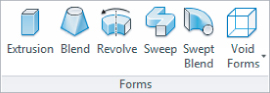
While working in the Family Editor, the Home tab of the ribbon contains the tools necessary for creating component families. The Forms panel of the Home tab holds the tools for building solid model geometry. In essence, all the tools are for creating extrusions; they just vary in their functionality. The Extrusion tool is the most commonly used because it is the most basic method for generating a solid. The idea behind creating a solid with the Extrusion tool is that you are going to sketch a shape and then extrude the shape to a defined depth.
When you click the Extrusion button on the Forms panel, the Modify | Create Extrusion contextual tab appears on the ribbon. This tab contains the tools needed to create the shape of the extrusion. The same drafting tools that are available for any common drafting task are available when sketching the shape for solid geometry. When working in sketch mode, the reference planes and any other graphics in the view will be displayed as a halftone, and the sketched line work will be magenta as a visual indicator that you are working in sketch mode.
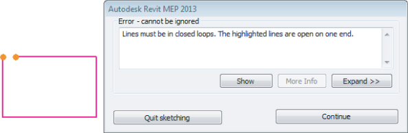
The sketch you draw for the shape of an extrusion can be as simple as a circle or as complex as you can imagine. The most important thing is to create a closed loop with no intersecting lines. You will receive an error message if you attempt to finish a sketch that does not form a closed loop. The Error dialog box allows you to continue sketching so that you do not have to start over, or you can quit the sketch, which will discard the work done while in sketch mode and return you to the Family Editor:
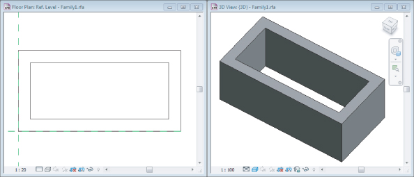
The sketch for an extrusion does not have to be a single, continuous set of lines. You can draw several shapes for a single extrusion as long as each shape is drawn in a closed loop. You cannot draw shapes that intersect each other. When you draw one shape inside another, Revit will extrude the area between the two shapes, as shown in Figure 17.1, which shows one rectangle drawn inside another. This is a useful method for reducing the need for void geometry in a family, because having a lot of voids in a family can adversely affect file performance.
Figure 17.1 Multishape extrusion
As you are working in sketch mode, you can define the properties of the extrusion prior to completing the sketch. Your sketch will define the shape of the extrusion, but you also need to determine the distance of the third dimension for your solid geometry. The Depth setting on the Options Bar allows you to set the distance for the extrusion, or you can use the Extrusion End and Extrusion Start parameters visible in the Properties palette while sketching. These values can be changed after the sketch is completed and the extrusion is made, but it is helpful to know the value prior to completing the sketch. The default value is 1′–0″ (300 mm), but if you change it, the value that you input will be used for the next extrusion, until you exit the Family Editor.
When you have completed the sketch for an extrusion, you must click the green check mark button on the Mode panel of the contextual tab in order to exit sketch mode and return to the Family Editor. If you want to cancel the creation of the extrusion, you can click the red X button on the Mode tab.
You can edit the shape of an extrusion by clicking it and dragging the grips that appear at each shape handle of the solid geometry. This includes changing the depth of the extrusion, which can be done by editing it in a view perpendicular to the view in which the extrusion was sketched. Using grips for editing is an easy but inaccurate method for changing the shape of an extrusion. To apply specific dimensions, you can edit the sketch by clicking the Edit Extrusion button on the contextual Modify | Extrusion tab that appears when you select the extrusion in the drawing area. Clicking this button activates sketch mode and allows you to make changes to the shape handles of the geometry by using dimensional input.
Blends
A blend is solid geometry that has a different shape at each end. The approach to creating a blend is the same as for an extrusion, with an extra step for creating the shape for each end. When you click the Blend button on the Forms tab, sketch mode will be activated, and you can begin creating the shape for the base of the blend. The base of the blend is the face of the solid geometry that is drawn on the reference plane with which the blend is associated. This is also referred to as First End in the properties of the blend. The sketch for the base geometry of a blend can contain only one closed loop.
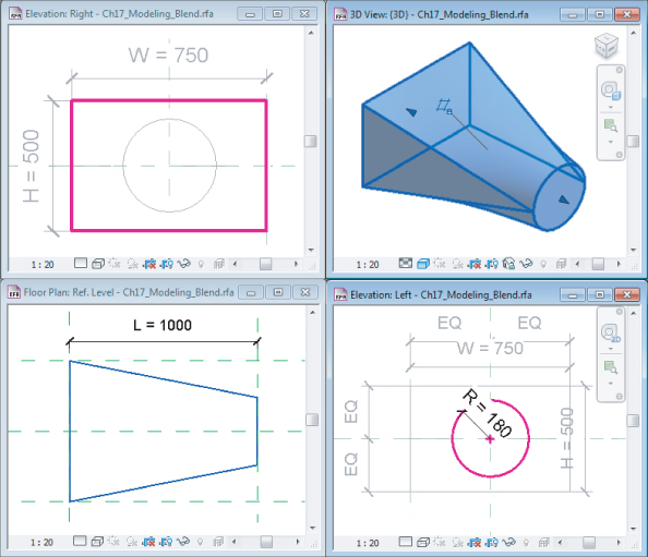
Once you have completed the sketch for the base, you must click the Edit Top button on the Mode panel of the contextual tab. This will keep you in sketch mode, and the base geometry will be grayed out. You can sketch the geometry for the top of the blend anywhere in the drawing area. The solid geometry will be extruded to connect the base to the top along the depth distance and any distances in the X or Y direction. Figure 17.2 shows the result of a top sketch that is a different shape to that of the base geometry.
Figure 17.2 Blend with different sketches
When you select a blend, the Modify | Blend contextual tab contains buttons that allow you to edit either the top or the base sketch by clicking the applicable button on the Mode panel. When you enter into sketch mode, you have the option to edit the other sketch if necessary by clicking the button on the Mode panel. You can also edit the vertices that are formed by the transition from the base shape to the top by clicking the Edit Vertices button.
The tools on the Edit Vertices tab of the ribbon, as shown in Figure 17.3, can be used to change how the transition occurs from the base shape to the top shape.
Figure 17.3 Editing vertices
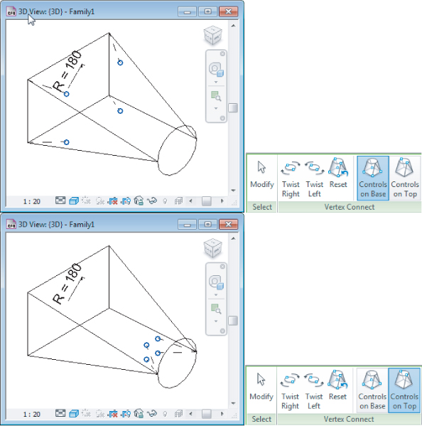
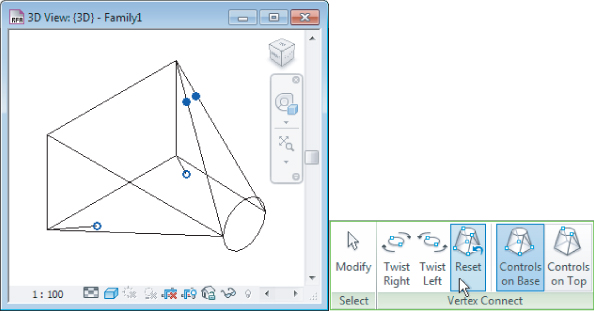
Depending on the shapes you have drawn, there will be different options for the vertices that define the transition. When editing the vertices of a blend, you can twist the vertices left or right. It is possible to twist too far, but you will not be warned until you exit sketch mode. Grips appear on the blend that allow you to edit vertices manually. The open circle grip is for adding a vertex, while the solid grip exists on a vertex that can be removed by clicking the grip, as shown in Figure 17.4. It is helpful to work in a 3D view when editing vertices because you can more clearly see the effect on the solid geometry. The Reset button on the Edit Vertices tab will return the orientation of the vertices to their original format.
Figure 17.4 Vertex editing grips
Once you have finished editing the vertices of a blend, you must click the Modify button on the Edit Vertices tab to return to the sketch mode tab. As always, you must then click the green check mark button to exit sketch mode. File Ch17_Modeling_Blend.rfa is provided as an example and can be found at www.sybex.com/go/masteringrevitmep2013.
Revolves
A revolve is an extrusion that follows a circular path around a specified axis. Using the Revolve tool allows you to create spherical solid geometry. You can start creating a revolve by clicking the Revolve button on the Home tab in the Family Editor. You can begin either by sketching the shape of the revolve or by selecting or creating the axis of rotation around which the shape will revolve.
The axis of rotation will always be perpendicular to the shape that you create, so it helps to first determine the orientation within the family of the shape you are creating. Once that has been determined, you will know where the axis needs to be and can switch to the appropriate view. For example, if you wanted to create a hemispherical solid that would lie flat when placed into a plan view, you would draw the axis perpendicular to the plan view. Switching to an elevation view in the Family Editor would allow you to draw the axis perpendicular to the plan.
Clicking the Axis Line button on the Modify | Create Revolve contextual tab activates sketch mode with two drawing tools available in the Draw panel of the tab. You can either draw the axis or pick an existing line. The reference planes that determine the insertion point of a family are good choices for an axis line. Once you have drawn or selected an axis, you will remain in sketch mode, but the Draw panel will populate with the usual drawing tools for creating the shape of the revolve.
The shape of the revolve can be drawn anywhere in the view in which the axis is drawn. When you are sketching the shape of the revolve, you must create a closed loop or multiple closed loops. You can sketch shapes away from the axis to create an interior circular space within the solid geometry, as shown in Figure 17.5.
Figure 17.5 Revolve shape drawn away from the axis
When you have completed the shape, you can click the green check mark button to exit sketch mode. The shape will be extruded in a circular path around the axis, forming the solid geometry. Figure 17.6 shows the resulting solid geometry formed by the shape and axis shown in the previous figure.
Figure 17.6 Revolve solid geometry
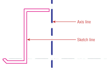
To create a spherical shape with a revolve, draw an arc shape adjacent to the axis line. Because the shape must be a closed loop, you will have a shape line at the axis, but this line will not be seen because it will be in the interior of the solid geometry. Figure 17.7 shows the sketch of a simple hemisphere solid.
Figure 17.7 Hemisphere revolve sketch
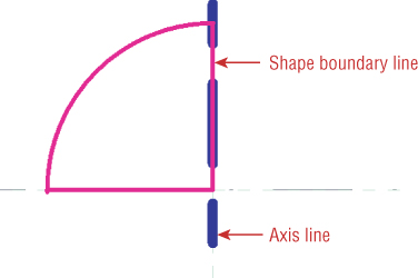
Unlike extrusions and blends, a revolve solid does not have a depth parameter. The depth or height of a revolve is determined by the sketch dimensions. A solid revolve has parameters that allow you to control how far around the axis the solid geometry is extruded.
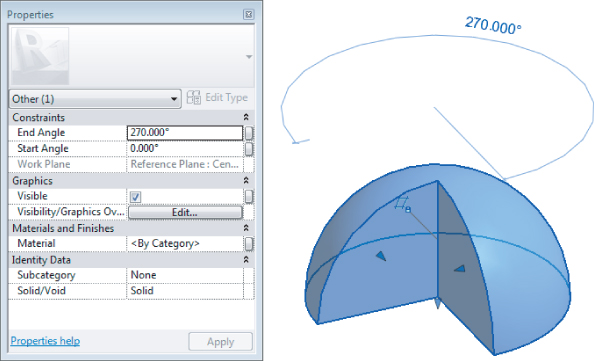
Adjusting the Start Angle and End Angle parameters adds further complexity to a solid revolve shape. Figure 17.8 shows the effects of values used in the parameters on a solid hemispherical revolve. Once you edit the parameters in the Properties palette, you can use the grips to pull the faces of the geometry around the axis. You can also select the temporary dimension that appears and input a value.
Figure 17.8 Revolve parameters
Files Ch17_Modeling_Revolve1.rfa and Ch17_Modeling_Revolve2.rfa are provided as examples and can be found at www.sybex.com/go/masteringrevitmep2013.
Sweeps
A sweep is an extrusion that follows a specified path. As you have just seen, a revolve is a special kind of sweep that follows a circular path around an axis. Using the Sweep tool allows you to specify the path for a shape to follow.
As with any solid geometry, it is important to first decide the orientation of the solid geometry within a family so that you can determine the location of the path for a sweep. When you click the Sweep button on the Home tab in the Family Editor, sketch mode is activated, and the contextual Modify | Sweep tab appears on the ribbon.
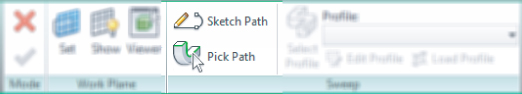
The first step in creating a solid sweep is to define the path of the extrusion. You can either sketch the path by using the standard drawing tools, or you can pick existing lines in the family. You cannot pick reference planes as a path for a sweep. However, you can pick reference lines, because they have a set length. You can also use existing geometry, either solid or void form, as a host for the pick lines. This gives you much more flexibility, especially if the host is parametrically driven.
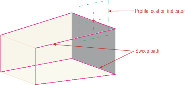
After creating the path for the sweep, you must click the green check mark button to exit sketch mode for the path. This returns you to sketch mode for the sweep geometry. With the path drawn, a profile location indicator is shown on the path, as seen in Figure 17.9. The profile location indicator can be moved anywhere along the path while sketching the path, which can be done by selecting the indicator and dragging it to the required location. This allows you to locate the profile parallel to a view plane that will make sketching the profile easier. This is especially useful when creating paths that contain arcs, because the profile may end up in the middle of an arc, at an angle at which it would be difficult to draw. The location of the profile plane will not have any effect on predefined profile families.
Figure 17.9 Sweep path and profile location
You can create the profile for the sweep by sketching, or you can select a predefined profile by clicking the Select Profile button on the Sweep panel of the Modify | Sweep contextual tab. When you click this button, any loaded profiles will be available in the drop-down list on the Sweep panel. If no profiles are available in the file in which you are working, you can click the Load Profile button on the Sweep panel. The content library that is loaded when you install Revit MEP 2013 contains a Profiles folder. From this folder, you can choose a predefined shape for use in your sweep geometry.
The profile for a sweep can be drawn in a view that is parallel to the profile location plane or in a 3D view where the path is visible. You can draw the profile in a plane that is perpendicular to the path but that is not parallel to the profile plane. This will cause an error when you attempt to complete the sweep by exiting sketch mode. The best option is to draw the profile in a plane that is both perpendicular to the path plane and parallel to the profile plane. When you select a predefined profile, it will automatically be placed in the profile plane.
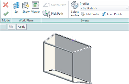
Once you have chosen or created a profile for the sweep, you can click the green check mark button to exit sketch mode and complete the solid geometry. To make changes to a sweep, select the solid geometry and click the Edit Sweep button. You can modify the path by clicking the Sketch Path button, or you can modify the profile by clicking the Select Profile button and then the Edit Profile button, as shown in Figure 17.10.
Figure 17.10 Edit Profile
You cannot change the location of the profile plane after the profile has been created, so it is best to determine its location when creating the path for the sweep. This can be done by carefully planning the path, because the location of the profile plane is the midpoint of the first line created in the path. File Ch17_Modeling_Sweep.rfa is provided as an example and can be found at www.sybex.com/go/masteringrevitmep2013.
Swept Blends
A swept blend is a combination of a sweep solid and a blend solid. This tool allows you to create a sweep that has two profiles, one at each end of the path. The solid geometry will transform from the shape of the first profile to the shape of the second profile along the path.
The process for creating a swept blend is similar to that of creating a sweep, with an extra step for defining the shape of the second profile. When you click the Swept Blend button on the Home tab in the Family Editor, sketch mode is activated, and you can draw or pick a path for the extrusion to follow. When you draw a path line, the first profile location will be at the start of the line, and a second profile location will be placed at the end of the line.
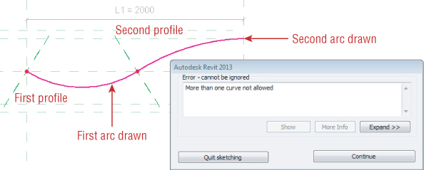
You cannot use multiple lines to create a path for a swept blend because the profile plane for the second profile occurs at the end of the first line drawn and any additional lines drawn afterward cannot be included in the path; you will receive an error, as indicated in Figure 17.11. This is also true if you use the Pick Path option. You can select only one line for the path.
Figure 17.11 Multiple lines for a swept blend path
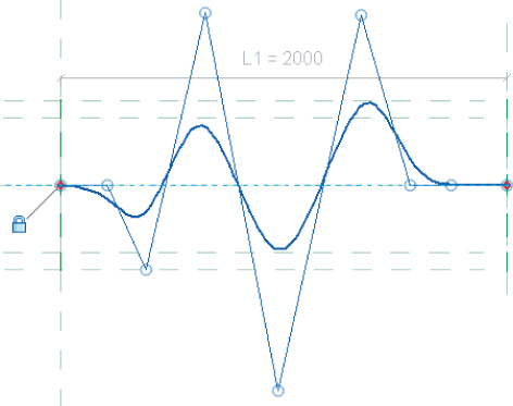
Instead of using multiple lines, you can use the Spline drawing tool for creating a complex path with a single entity. Figure 17.12 shows how a spline can be drawn to represent the same shape as shown in the previous figure.
Figure 17.12 Spline path for a swept blend
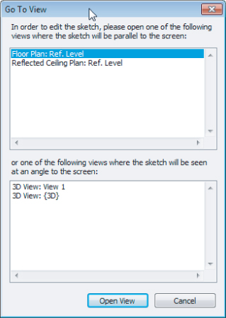
When you click the green check mark button to exit sketch mode for the path, the Swept Blend panel provides tools for defining each of the profiles. Each profile can be drawn, or a predefined profile family can be used. After you click one of the profile buttons, you must click the Edit Profile button to draw the shape. The Go To View dialog box will appear so that you can choose a view where the profile sketch can be drawn. Once you have finished the profile shape, you can exit sketch mode by clicking the green check mark button. You can then create the second profile by clicking the Select Profile 2 button, and then the Edit Profile button.
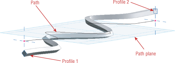
Because you are defining each end of a swept blend solid with a profile shape, you can create a twist in the solid geometry by locating the profile sketches at different elevations from the plane of the path. Figure 17.13 shows an example of a swept blend in which the profiles are drawn above and below the plane of the path, creating a solid that not only changes shape from one end to the other but also changes elevation.
Figure 17.13 Swept blend with profiles offset from the path plane
File Ch17_Modeling_SweptBlend.rfa is provided as an example and can be found at www.sybex.com/go/masteringrevitmep2013.
Joining Geometry
In some cases, it may be easiest to create a solid form by creating multiple individual solids and then combining them. When you select an extrusion in the Family Editor, the Geometry panel on the contextual tab contains tools for joining geometry.
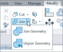
When you join geometry in the Family Editor, you create a union between the selected solids. When geometry is joined, you can select all the forms by placing your mouse pointer over one of the forms and using the Tab key to select any forms joined to it. This makes for easier editing in the Family Editor, and the joined geometry can be assigned a material property, or the visibility of the joined multiple objects can be controlled with one setting.
Each individual form within a set of joined geometry can be edited normally. Solid forms do not even need to be touching each other to be joined. If you want to break the relationship of forms that are joined, you can select one of the solid forms and click the Unjoin Geometry option on the Join button. You will then be directed to select the solid geometry that you want to be unjoined from other geometry.
Voids
To this point, all the discussion on modeling tools has been for creating solid geometry, but sometimes it is necessary to create a void form. Voids can be used to cut shapes out of solid geometry and, in the case of hosted families, voids can be used to cut the host. Additionally, the void form can be utilized as a framework for hosting solid geometry. Some solids are easier to create by modeling a form and then using a void form to remove a portion of the solid geometry.
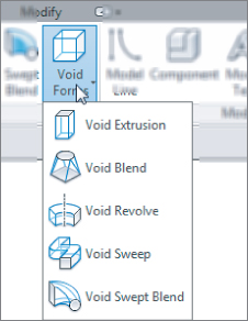
The same tools for creating solid geometry are used for creating void geometry. The Void Forms button on the Home panel of the Family Editor contains a drop-down list of the tools for creating a void.
Because the form tools are so similar, you can even create solid geometry and then change it to a void by editing the Solid/Void parameter in the properties of a solid form. Voids can also be changed to solid geometry by editing the same parameter.
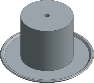
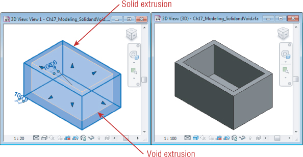
In an earlier example, you saw a multishape extrusion drawn as one rectangle inside another to create a solid with its center hollowed out all the way through (see Figure 17.1). If you did not want the open space in the center to pass all the way through the solid, you could create multiple solids that result in the desired form, or you could use a void form to cut out the desired space in the solid, as shown in Figure 17.14.
Figure 17.14 Void geometry in a solid form
File Ch17_Modeling_SolidandVoid.rfa is provided as an example and can be found at www.sybex.com/go/masteringrevitmep2013.
When you create a void form while in the Family Editor, it will appear in the 3D views as a transparent form and as orange lines in plan and elevation views, as long as it is not cutting any solid geometry. The void will not automatically cut any solid geometry unless it is drawn overlapping the solid geometry. So, if you were to draw a void form independent from any other geometry in the view and then move the void so that it overlaps solid geometry, the solid would not be cut.
You can tell the void form which solid geometry to cut by selecting it, and then clicking the Cut button on the Geometry panel of the contextual tab. You can select the void or the solid geometry first, and then select the other to establish the cut relationship.
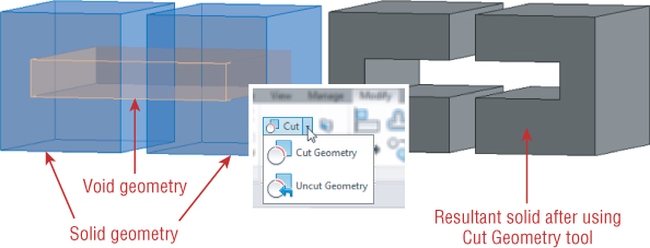
You can establish the cut relationship with a void and a solid before they are overlapping. After you use the Cut tool and create the relationship, the void will cut the solid when it is moved to overlap the solid. You can create a cut relationship between one void and multiple solid objects, as shown in Figure 17.15. The void form has been highlighted in this image to illustrate that it is a single void cutting multiple solid objects.
Figure 17.15 Void cutting multiple solids
File Ch17_Modeling_MultipleSolidandVoid.rfa is provided as an example and can be found at www.sybex.com/go/masteringrevitmep2013.
In the case of a hosted family, you can use the Cut tool to create a cut relationship between a void and the host geometry. This is useful for lighting fixture and air terminal families, when you want to show that the component requires an opening in its host. This type of relationship can be established within face-hosted or with model-hosted families. However, when using face-hosted families in a project, the void will not cut a linked host face.
Voids should be used only when necessary to define the shape of a solid. Consider all the other solid modeling tools to create forms before resorting to using voids. It has been documented that having many voids in families, or having many families with voids in a project, can negatively affect file performance.
For some families, it may be tempting to use void forms to define the required clearance space around mechanical and electrical equipment. There are other methods to define these spaces without burdening your projects with void geometry. For more information on creating clearance spaces within families, see Chapter 19, “Creating Equipment.”
Mastering the tools for creating solid geometry will make content creation an efficient part of your Revit MEP 2013 implementation. Practice creating different types of solids by completing the following exercise:
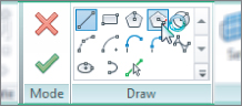
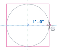
Figure 17.16 Create bottom sketch of blend
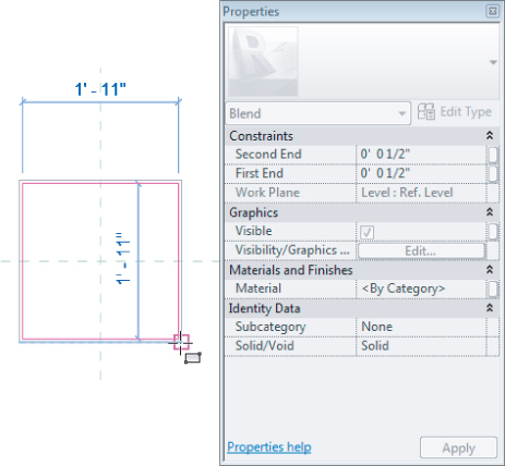
Figure 17.17 Create top sketch of blend
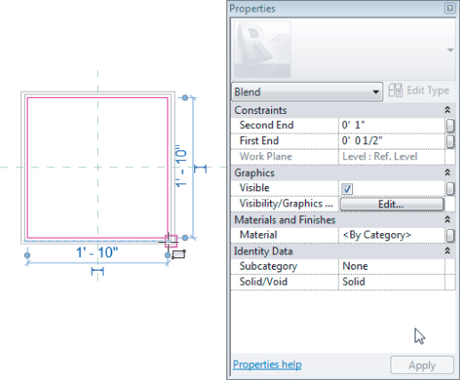
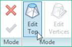
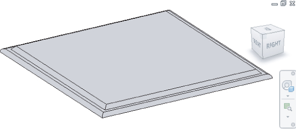
Figure 17.18 Default 3D view
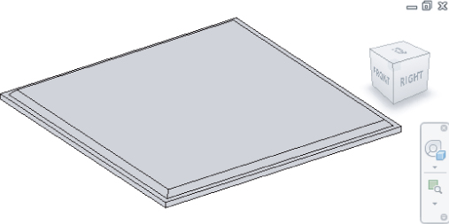
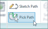
Figure 17.19 Selecting path of sweep
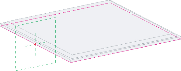
Figure 17.20 Sketching sweep
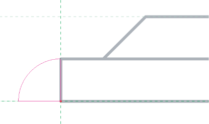
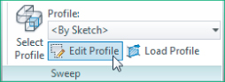
Figure 17.21 Completed form
Reference Planes and Lines
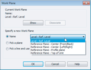
When you begin to create a solid, it is important to understand how the current view will affect the orientation of the solid you create. When you click one of the buttons on the Form panel of the Home tab, you will be taken into sketch mode for the solid. A contextual tab appears on the ribbon with tools for generating the sketch, or shape, of the solid. The view you are in determines the plane for the sketch, and the depth of the solid will be perpendicular to the sketch plane. If you are working in a file that contains multiple planes that are parallel to the current view, you can select a plane to which you can associate the extrusion by clicking the Set button on the Work Plane panel of the contextual tab. When you click the Set button, the Work Plane dialog box will appear. You can choose the desired plane from the drop-down list, as shown in Figure 17.22.
Figure 17.22 Work Plane dialog box
If you choose a reference plane that is not parallel to the current view, the Go To View dialog box will appear after you click OK in the Work Plane dialog box. The Go To View dialog box, shown in Figure 17.23, offers views that exist in the family file that are parallel to the selected reference plane. You can also choose a 3D view in which to work if you are more comfortable working in 3D to generate solid geometry. You can click the Show button on the contextual tab for a visible reference of the plane chosen for the sketch. This is especially helpful when creating a sketch in a 3D view.
Figure 17.23 Go To View dialog box
You do not have to set the reference plane to begin sketching the shape of the solid. Sketching it directly in the view will associate the solid geometry with the plane of that view, such as the reference level of a family.
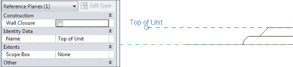
When you are using reference planes to build solid geometry, it is a good idea to give any custom planes a name so that they can be easily identified and selected from the list in the Work Plane dialog box. This can be especially helpful when creating families with multiple solids; giving reference planes names such as Top of Unit or Face of Device aids in associating other geometry within the family to the plane, as shown in Figure 17.24.
Figure 17.24 Named reference planes
You can control how a reference plane in a family is accessed when the family is loaded into a project by editing the Is Reference parameter, as shown in Figure 17.25. You can set the parameter to associate the plane with the orientation of the family by choosing any of the directional choices such as Front, Back, Bottom, Center (Left/Right), and others. You can also choose whether the reference plane is used for dimensioning when the family is loaded into a project. These options are as follows:
Figure 17.25 Is Reference
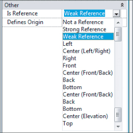
Not A Reference
When placed into a project, the plane will not be available for dimensioning or alignment. This is a good setting for planes created in a family that are used only for association within the family. It will prevent unwanted selection or highlighting of a family when your mouse pointer passes over the plane.
Strong Reference
When the family is placed into a project, the plane will be the first choice for temporary dimensions. This setting is best used for planes in a family that define the portions of a family to which you would dimension or align when using the family in a project.
Weak Reference
This setting for the parameter is for when you want to be able to dimension or align to the plane, but do not want temporary dimensions applied to the plane when placing the family in a project.
The Defines Origin parameter allows you to set a reference plane as one of the planes of the origin of a family. Two planes must be set as defining the origin, and the planes must intersect. The intersection of the planes in plan view will determine the insertion point of the family.
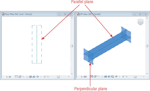
Reference lines are useful in creating solid geometry when you do not want to create an infinite plane of reference. Unlike reference planes, reference lines have a start point and an end point. When you draw a straight reference line, two planes are formed at the line. One plane is parallel to the plane in which the line is drawn, and the other is perpendicular to that plane. This allows you to use the reference line in views parallel and perpendicular to where it is drawn. Figure 17.26 shows a reference line that has been selected to show the planes associated with the line. Arced reference lines can be used for reference but will not create planes.
Figure 17.26 Reference line and its planes
Reference lines can be dimensioned when a family is placed into a project, and they also have a parameter that allows you to set them as a strong or weak reference or as not a reference at all. You cannot use reference lines to define the origin of a family.
Solid geometry can be aligned to reference lines in the same way as to reference planes. Using reference lines and planes is the most effective way to create parametric behavior of solid geometry within a family.
Constraints and Dimensions
Making the solid geometry in your families parametric gives you the ability to create multiple types within a single family and offers a higher level of management and control of the properties of components. The key to making your solid geometry parametric is to constrain the geometry to reference planes and lines. This enables you to apply the parametric behavior to the planes and lines, which allows for multiple solid forms to react to changes to the parameters. Although you do have the ability to assign parametric constraints directly to the solid geometry, it is recommended that you assign it to reference planes or lines so that changes to a solid that affect other solids within the family are more easily achieved and managed.
Geometry can easily be constrained to a reference plane by using the Align tool on the Modify tab, or you can simply drag the edge of a solid to a reference plane or line, and it will snap into alignment. Once aligned, the padlock grip appears, allowing you to lock the alignment.
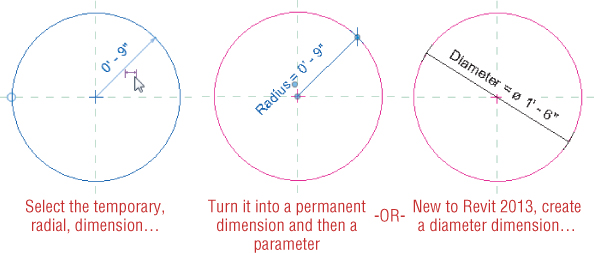
Some solid forms do not need a reference plane or line to be parametrically managed. Whenever you are sketching a circle and want to control the radius with a parameter, you can apply the parameter directly to the sketch. This is done by activating the temporary dimension that indicates the radius when sketching the circle. Clicking the dimension grip will change the temporary dimension to a permanent one, which can then be assigned to a parameter. Alternatively, and new to Revit 2013, you can now create a diameter dimension, as shown in Figure 17.27.
Figure 17.27 Radial and Diameter dimensions
When you complete a sketch that contains dimensions within the sketch, the dimensions will not show unless you are in sketch mode. You can constrain sketch lines to reference planes while working in sketch mode but, if you are using dimensional constraints, it is best to put the dimensions directly in the family so that they will be visible while you are working on the family. It can be very frustrating to place a dimension only to find that one already exists in the sketch of a solid.
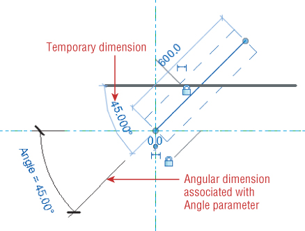
Creating angular constraints is often necessary for solid geometry. When you need to create angular parametric behavior for a family, it is best to use reference lines instead of reference planes. The location of the end point of a reference line can be constrained so that the line can be rotated with the end point serving as the axis of rotation. An angular dimension can be used to create the parametric behavior of the reference line, as shown in Figure 17.28. The padlock grip indicates that the reference line has been locked to the horizontal reference plane, although it is not necessary to lock the end point to the reference plane if the reference line is drawn connected to the plane.
Figure 17.28 Reference line with angular parametric behavior
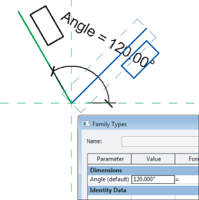
This type of angular constraint is useful for rotating solid geometry within a family. Figure 17.29 shows an extrusion that was modeled in the vertical plane of the reference line. Because the plane of the line was used, the extrusion is associated with the line so that, when the angle of the line changes, the solid will stay with it. The dashed lines indicate the original location of the line prior to changing the angle parameter to 120 degrees.
Figure 17.29 Extrusion constrained to the reference line
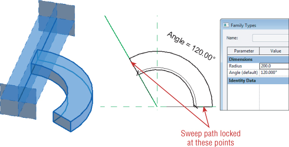
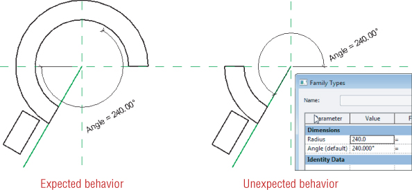
Although reference lines work well for this type of constraint and parametric behavior, they can cause undesired results when the angle of solid geometry is supposed to change while the geometry remains in a fixed location. The solid geometry shown in Figure 17.30 is a sweep with a rectangular profile. The path of the sweep is an arc that is locked to the reference line and to the reference plane. As the Angle parameter is modified, the length of the sweep increases. A Radius parameter has also been applied for the sweep path.
Figure 17.30 Sweep constrained to the reference line
This type of parametric relationship will behave as expected—up to a certain point. Flexing the family reveals that, at larger angles, the geometry may not stay associated to the reference line, which could cause an incorrect representation of the solid, as shown in Figure 17.31. Notice that the solid geometry could change orientation across the horizontal reference line and appear to be mirrored instead of swept through 240 degrees.
Figure 17.31 Undesired sweep geometry from the angular constraint
Different angles input into the parameter result in different undesired behavior of the solid geometry. The purpose of this example is not to point out shortcomings of the software, but to demonstrate that one choice for creating an angular constraint may not work for all situations.
An alternative solution for this scenario would be to use an angular dimension of the sweep path itself instead of constraining to a reference line. Figure 17.32 shows the dimension parameters applied to the path of a sweep. The angular dimension was created by selecting the path and then activating the temporary dimension, which was then associated with the angle parameter.
Figure 17.32 Sweep path with parametric constraints
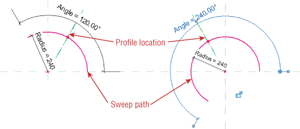
With the path of the sweep being defined by the angle instead of its association to a reference line, the desired results for the solid geometry can be achieved.
File Ch17_Modeling_ReferenceLINES.rfa is provided as an example and can be found at www.sybex.com/go/masteringrevitmep2013.
Visibility Control
The visibility parameters of solid geometry provide useful means for controlling the behavior of solids in a family that is used in a project. For many MEP discipline families, the actual solid geometry is not shown in plan views, but instead a symbol is used. This is especially true for electrical devices and even some light fixtures.
If you are concerned about file performance, it is a good practice to limit the visibility of solid geometry to only the types of views where it is necessary to be seen. Symbolic or model lines can be used to represent the geometry in views where the solid does not have to be shown, such as plan views or reflected ceiling plans. Setting the visibility of solid geometry to display in 3D views, sections, and elevations is important because it helps keep your project coordinated by allowing you to locate items when a section or elevation view is created, without having to draw additional line work in the section or elevation view.
In some cases, you may also want to control the visibility of solid geometry based on the detail-level setting of a view. For example, you may set the visibility of the solid geometry in a power receptacle family so that the geometry shows only in views set to Fine detail. This enables you to see the actual location of the receptacles quickly by switching the view detail level for instances where you are trying to coordinate exact locations. It also benefits other disciplines, such as architectural, that may want to see the receptacle geometry in a section or elevation.
To set the visibility of solid geometry in the Family Editor, select the geometry and click the Visibility Settings button located on the Mode panel of the contextual tab that appears on the ribbon.
In the Family Element Visibility Settings dialog box, you have options for setting where the solid geometry will be visible when the family is used in a project. Figure 17.33 shows the dialog box and the available options.
Figure 17.33 Family Element Visibility Settings dialog box
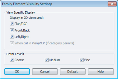
All solid geometry is visible in 3D views when the category of the family is visible. The View Specific Display options allow you to select other types of views where the solid geometry will be visible. Keep in mind that, for face-hosted families, the Front/Back setting will display the geometry in a plan view when the geometry is hosted by a vertical surface. The Left/Right setting is for section and elevation views taken from the side of the geometry. One of the options is to display the geometry when the cut plane of a view intersects the geometry. This option is not available for all categories of families, and is typically used for architectural and structural types of families such as doors or windows.
In the Detail Levels section of the dialog box, you can select the detail levels in which the geometry will be visible. When using symbolic or model lines to represent the geometry in plan and Reflected Ceiling Plan (RCP) views, consider what detail level will be used for section, elevation, and 3D views so that the geometry will display when desired. When creating duct and pipe fitting and accessory families, be sure to set the Detail Levels settings within the Family Element Visibility Settings dialog box to match the behavior of duct and pipe system families so that the solid geometry will display in Medium detail for duct and Fine detail for pipe-related families. Any model lines used to represent the objects should display only in Coarse detail for duct and Coarse and Medium for pipe.
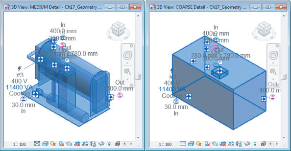
In some cases, you may want to represent an object with a very simple shape for plans using Coarse detail and a more realistic shape in smaller-scale views using Fine detail. The box shown in Figure 17.34 is set to display at Coarse detail, while the more detailed solid geometry displays at Medium and Fine detail levels.
Figure 17.34 Geometry display at different detail levels
The visibility settings you apply will not affect the geometry while you are working in the Family Editor. Solid geometry will remain visible in the Family Editor so that you can work on the family. In 3D views within the Family Editor, solid geometry will appear halftone if the visibility settings of the geometry would cause the object not to be visible in the same type of project view. In other words, if you set an object to display only in Fine detail, and your 3D view in the Family Editor is set to Medium detail, the solid will be halftone in the Family Editor 3D view. This is a helpful visual aid when working in a family to understand the visibility behavior of the geometry.
The visibility of solid geometry can also be controlled by the Visible parameter in the properties of the geometry. This is a Yes/No parameter that simply determines whether the geometry is visible. This parameter can be associated with another parameter defined in the family for control of the solid visibility when the family is used in a project.
Another option for the visibility of solid geometry is to assign a material to it by using the Material parameter. You can create a custom material type with settings that are desired for use in your projects. One example is to create geometry in a family that represents the required clearance space for equipment. Along with visibility control settings, a material can be applied to the solid geometry to make it semitransparent when viewed in a 3D project view. See Chapter 20, “Creating Lighting Fixtures,” for more details.
When you are considering the visibility of solid geometry in a family, keep in mind that the visibility of the entire family is controlled by its category. In some cases, you may want to control individual components independently from the family category. You can create subcategories within a family by clicking the Object Styles button on the Manage tab in the Family Editor. Once you have created a subcategory, you can assign solid geometry to the category by using the Subcategory parameter in the properties of the geometry.
File Ch17_Geometry Display_Chiller.rvt is provided as an example and can be found at www.sybex.com/go/masteringrevitmep2013.
In-Place Massing
Although the tools in this chapter have been aimed at the Family Editor, those same tools can be used in the project environment to create a building form. Although this task may traditionally be the preserve of the design architect, especially during the concept stage, the building services design engineer could also use these tools to create a building object that can be used for analysis from the early stages. This may occur if the architectural models are too inaccurate to use for analysis or, as mentioned in Chapter 5, “Multiplatform Interoperability: Working with 2D and 3D Data,” are not available at all.
The exercise in Chapter 5 took you through the process of creating a wireframe building model. The following exercise takes this a step further as you generate an in-place mass from which very basic analysis can be achieved:
Figure 17.35 Show Mass Enabled
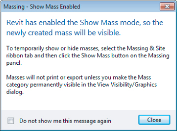
Figure 17.36 The Create Form button
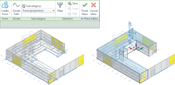
Figure 17.37 Stretching the Mass object
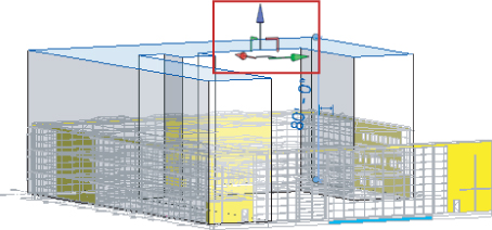
Figure 17.38 Mass Floors dialog box
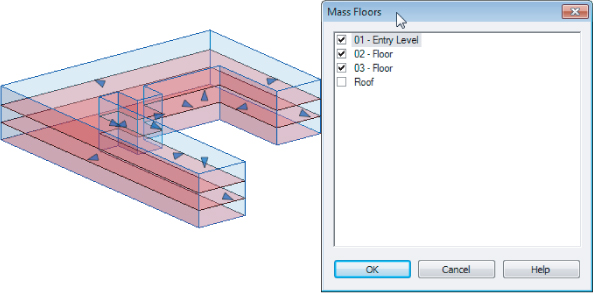
Figure 17.39 Mass Floor Schedule
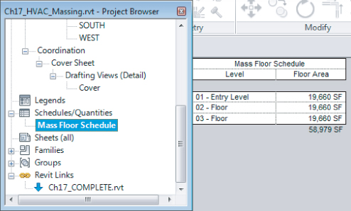
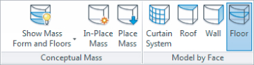
Figure 17.40 Creating floors
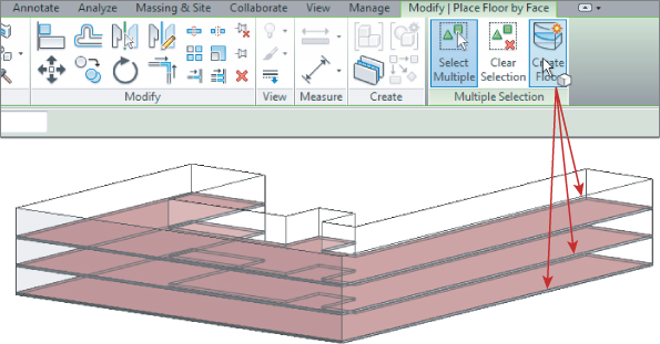
Figure 17.41 Creating walls
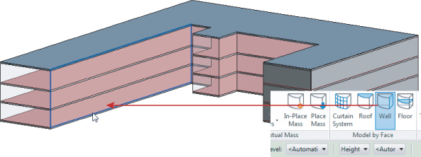
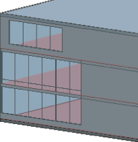
Figure 17.42 Creating curtain walls
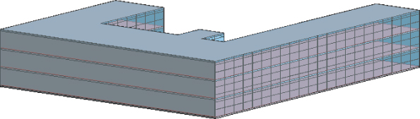
Figure 17.43 Options Bar
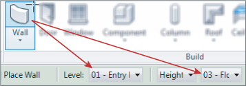
Figure 17.44 Walls overlapping
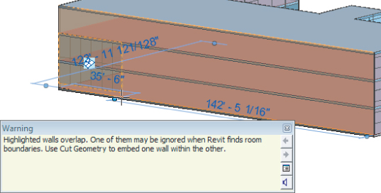
Figure 17.45 Walls cut
The Bottom Line
Model solids and voids.
Being able to model efficiently will decrease the time you spend creating content, and give you more time to spend on design decisions. Solid geometry is crucial for the physical coordination of components to achieve a design that will result in fewer changes during construction—when changes are the most expensive.
Master It
Several tools are available to create the shapes needed to represent MEP discipline components. Each tool generates an extrusion in a unique way. Describe the difference between a swept blend and a regular sweep.
Orient geometry by using reference planes and lines.
Reference planes and lines are the most effective way to define the orientation of solid geometry within a family. Reference planes define how an object will be inserted into a project.
Master It
Knowing the resulting orientation of an extrusion prior to creating it will save lots of time by not having to duplicate modeling efforts. Nothing is more frustrating than taking the time to create a solid, only to find out that it is in the wrong plane. Describe the process for creating an extrusion that is associated with a custom reference plane.
Ensure the parametric change capability of models.
Building solid geometry to represent MEP discipline components is good. Building the geometry with parametric-change capabilities is even better.
Master It
Solid geometry can be defined by parameters that can change the size or shape of the geometry. Reference planes and lines are an important part of creating parametric behavior. Why?
Determine optimal visibility settings for solids.
The visibility behavior of solid geometry plays an important part in the creation of consistent and coordinated construction documents.
Master It
It is important to know how a family will be used in a project to determine the visibility settings required for the solid geometry in the family. Why is it important to set the Detail Level visibility settings for pipe- and duct-related families?
Create in-place Mass objects for analysis and documentation.
In-place Mass objects allow the designer to quickly produce a building form at a time when the project architect may not be able to provide a model that is suitable for early analysis purposes.
Master It
Using massing tools can speed up the design process. What tools would you use to quickly model glass and windows?