
Chapter 13
Power and Communications
Modeling power systems with a building information modeling (BIM) solution such as Autodesk® Revit® MEP 2013 is just as important to project coordination as modeling systems that contain large amounts of physical data, such as HVAC systems. As with a lighting model, the key element to a power systems model is the data within the model elements. This information determines how systems can be put together. It can be extracted from the model for use in analysis and to aid in design decisions.
There is something to be said for the physical model of a power system as well. Receptacles and junction boxes are relatively small compared to other system components, but with a large number of them in a project, the potential for interference is increased.
Building communication systems have become more complex with advances in modern technology. Voice and data networks and devices, along with security and fire alarm systems, are major design elements of new construction as well as renovations of existing buildings. Revit MEP 2013 has the tools necessary for you to communicate your design in a 3D model that contains the important data needed to ensure an efficient and effective workflow. Electrical equipment can be large and usually requires a clearance space around the equipment for service. Large conduit runs and cable trays are an important coordination consideration as well.
In this chapter, you will learn to do the following:
- Place power and systems devices into your model
- Place equipment and connections
- Create distribution systems
- Model conduit and cable tray
Modeling Methods for Power and Systems Devices
Power and systems plans can easily be created in your Revit model to show the locations of outlets and other types of electrical devices. You can use symbols, model elements, or a combination of the two to represent the design layout. The choice you make depends on what level of coordination you want to achieve and how much information you intend to extract from the design.
Revit MEP 2013 comes with a few basic device components to use for creating electrical layouts. Because you do not need to go into great detail to model these small elements, it is easy to create your own device families that match your company standards for electrical symbols. We cover creating electrical devices in Chapter 21, “Creating Devices,” and we cover creating symbols in Chapter 18, “Creating Symbols and Annotations.”
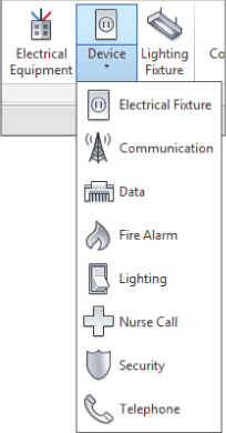
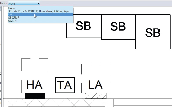
The Device button on the Systems tab is used for placing a device into your model. This is a split tool with two parts. Clicking the top half of the button invokes the command to insert an electrical device. Clicking the bottom half of the button reveals a drop-down of specific categories of devices, as shown in Figure 13.1. When you select a specific type of device from the drop-down menu, the top half of the Device button changes to match the category you have chosen. Clicking the top half of the button will invoke the command to insert that type of device. Selecting a device from a specific category will cause the Type Selector to populate only with devices in that category.
Figure 13.1 Drop-down menu from the Device button
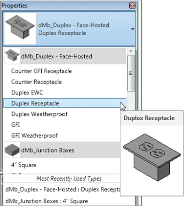
Select the Electrical Fixture category to insert power receptacles into your model. It is a good practice to go directly to the Type Selector after choosing a device category to insert. The Type Selector drop-down list contains all the families in the selected category that are loaded into your project. The list is organized by the family names highlighted in gray, with the family type names listed beneath each one. At the bottom of the list, you will see a section with the most recently used families in that category. With tooltip assistance turned on, placing your mouse pointer over a family in the list will reveal a thumbnail view of the family. Figure 13.2 shows an example of the Type Selector drop-down for the electrical fixtures loaded in the project.
Figure 13.2 Type Selector drop-down
If there is no family loaded into your project that matches the category you selected from the Device drop-down button, you will be prompted to load one. The default library contains an Electrical folder, with receptacle families located in the Terminals subfolder found in the Electric Power folder. The Information And Communication folder contains families to be used for communications systems, including the Fire Alarm folder that has families for fire alarm design. All of these types of devices can easily be created because the level of model detail is not as important as the connector data. One family can be duplicated several times and given a different connector type in order to build a library of power and communications families.
The library folder structure for Revit MEP 2013 has changed from previous versions, so it is a good idea to take some time to familiarize yourself with where families are located.
Using Annotation Symbols
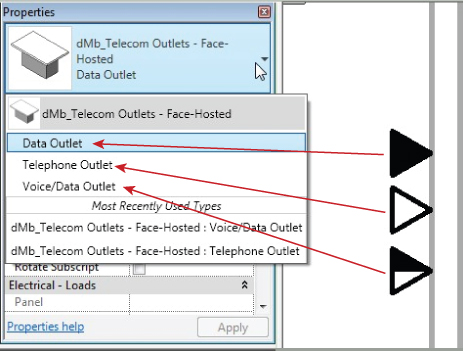
Power and communications plans are typically shown schematically by using symbols to represent the various devices and outlets. Because of this, annotation symbols are another key element of the families used to represent the design. Different symbols can be used within the same family to represent the different types of that family. This will help reduce the number of families required to maintain a complete library for design and reduce the number of families loaded into your project. Using multiple annotations within a family makes for easy modification of your design. Figure 13.3 shows a single communications family with three types utilizing different symbols.
Figure 13.3 Multiple symbols in a device family
Using Face-Hosted Families
It is best to use face-hosted families to model your receptacle and communications layouts. Unless otherwise noted, the examples discussed in this chapter will refer to face-hosted family types. This gives you the freedom to place the devices on any face within the building model. These types of components will move with their hosts, so you will spend less time moving your devices around to keep up with changes to the building model. If a device host is deleted from the model, the device will remain in place. This gives you the opportunity to relocate or remove the device manually and adjust any associated circuitry.
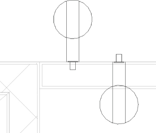
When you select a face-hosted device type to place in the model, the default placement is to a vertical surface. When you place your mouse pointer near a vertical surface such as a wall, the symbol used to represent the device will appear. You can press the spacebar to flip the orientation of the device to either side of the face upon which you are placing it. Figure 13.4 shows a receptacle hosted to each side of the face of a wall. As you can see, this not only affects the symbol orientation but affects the model component as well.
Figure 13.4 Orientation of receptacles on a vertical surface
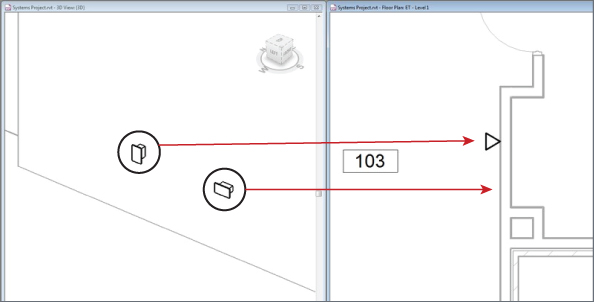
If the device family you are using is not face hosted, pressing the spacebar will rotate the device in 90-degree increments parallel to the plane of the current view. After a face-hosted device has been placed, selecting it and pressing the spacebar will rotate the device 90 degrees parallel to the host face. This will cause your annotation symbol to “disappear” because annotations are visible only in views parallel to the view in which they are placed. Figure 13.5 shows two systems outlets hosted by a wall. Both outlets were placed the same way, but the outlet on the right was rotated using the spacebar after placement. Notice that the annotation symbol of the outlet on the right is not visible in plan view.
Figure 13.5 Outlet placement and rotation
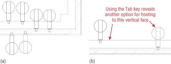
Take care when placing devices on walls that contain multiple layers. Because of the structure of these types of walls, there can be several vertical faces on which to host the device, as shown with a power receptacle in Figure 13.6. You can use the Tab key to cycle through the different hosting options for the face on which you are trying to place the device.
Figure 13.6 (a) Multiple hosting options in a compound wall; (b) using the Tab key for hosting options
Because any 3D surface can be used as a host, you can place devices on curved walls, and the component and symbol will follow the curve as you move your mouse pointer along the surface. There is no need to rotate the symbol or component after placement, saving time in laying out your design.
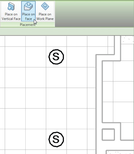
Devices or outlets can be placed in floors or ceilings as well. To do so, you need to select the Place On Face option from the Placement panel of the contextual tab after you have chosen your device. This enables you to place devices such as speakers onto the ceilings within your model, as shown in Figure 13.7.
Figure 13.7 Devices placed onto a ceiling face
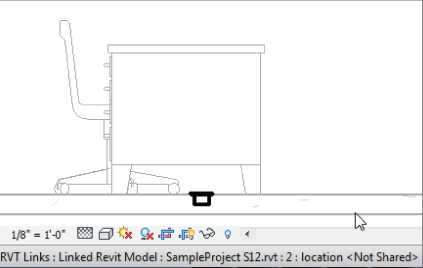
When you place devices or outlets onto floor objects, be sure that you are selecting the appropriate floor as a host. Often in projects, the architect will model a floor object to act as a placeholder to show a floor in section or elevation views while the actual floor is being modeled in the structural project file. Use the Visibility/Graphic Overrides settings to turn on the appropriate floor object for hosting. This will ensure that, if the floor object is removed from the architectural model, your devices or outlets will remain hosted. Use the cursor tooltip or status bar to confirm that the correct floor is displayed in your view, as shown in Figure 13.8.
Figure 13.8 Floor-hosted device in appropriate host
Avoiding Interference of Symbols
Because of the schematic nature of construction documents for electrical designs, it can sometimes be difficult to place components without causing interference between the symbols used to represent those components. Figure 13.9 shows two power receptacles placed in a model at the correct location for the intended design, but the symbols used for construction documentation are interfering with each other.
Figure 13.9 Receptacles with interfering symbols
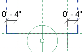
This scenario raises the question of whether it is more important to build the model accurately or to show the schematic symbols correctly for construction documentation. Using the functionality of families and nested annotations, Revit MEP gives you the ability to do both. Parameters within your component families can be used to offset the annotation symbols nested within them from the actual model components. In Figure 13.10, you can see how an offset parameter is used to shift the receptacle annotation of a family, allowing for both accurate placement of the receptacles and correct symbolic representation.
Figure 13.10 Receptacle annotation offset
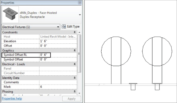
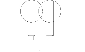
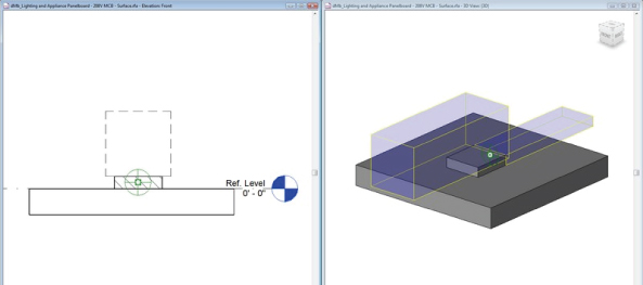
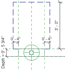
This functionality can also be used for devices that are vertically aligned in the model. In plan view, these devices would appear to occupy the same space. A standard practice is to show one receptacle symbol at the location on the wall and another symbol offset from the wall at the same location. By using an offset parameter, the same result can be achieved. Figure 13.11a shows an instance parameter used to offset the symbol of a receptacle that is above another, and Figure 13.11b shows a section view and plan view of the receptacles. Using this functionality maintains both the model integrity and the schematic plan.
Figure 13.11 (a) Instance parameter settings for a symbol offset; (b) section and plan views of the receptacles
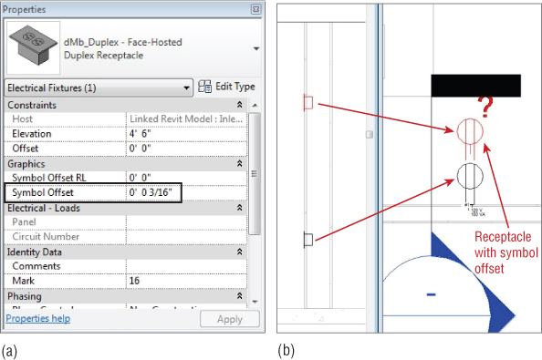
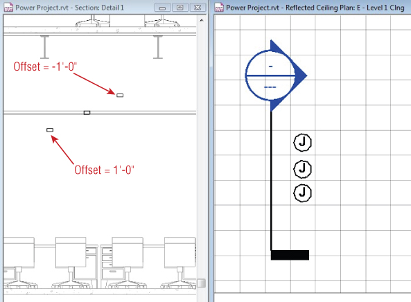
Other devices, such as junction boxes, can be placed in the model in the same manner as receptacles or communication outlets. Creating different types within a junction box family is a good way to keep track of specific loads. Junction boxes for systems furniture can be hosted by the floor to show location, if the furniture is not modeled in 3D. Boxes that are located above the ceiling can be hosted by the ceiling object and given an offset to maintain their distance from the ceiling if the ceiling height should change. When you place a junction box in a reflected ceiling plan and give it an offset, the box will offset from the front face of the ceiling. This means the box will move toward the floor, so if you need the box to be above the ceiling, you will have to give it a negative offset, as shown in Figure 13.12.
Figure 13.12 Ceiling junction boxes with offsets
Creating Circuits
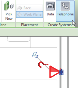
When you place devices or outlets into your project, you can assign them to a system by creating a circuit for them. The connector in the family determines the type of circuit you can create. When you select a device in the model that contains a connector, the Create Systems panel appears on the contextual tab for that type of device. Clicking the button will create a circuit for that device. At this point, it is not necessary to select a panel for the circuit because you may not have placed the equipment yet, but having your devices on circuits will improve file performance. Figure 13.13 shows the available circuit types for a device that contains both a data connector and a telephone connector. A circuit can be created for each type of connector in the family.
Figure 13.13 Circuit options for a multi-connector device
Some of your devices may require multiple connectors for different disciplines, such as a floor box with both power and data outlets. If your project contains several of these devices, it is best to have the nested symbolic families on different subcategories within the multi-connector device family. This way, their visibility can be easily controlled in both power and communications views.
Creating a Fire Alarm System Model
Fire alarm systems are often shown with the electrical construction documents, although on occasion they are handled separately. The same tools that allow you to model other electrical systems can be used for fire alarms. As with any unique system, it is recommended that you create a workset for the fire alarm system to allow for multiple user access to the model. If a consultant uses Revit MEP to create the fire alarm system for your project, you can link in their model for coordination.
The number of fire alarm device families that are included with the installation of Revit MEP has increased over the years, but you may need to create devices that match your company standards. Fire alarm construction documents are usually schematic in nature, so the annotation symbols are the important part of your fire alarm system families. The Manual Pull Station.rfa family provided with Revit MEP 2013 can be copied and modified with the appropriate annotations to build your library of fire alarm devices. For more information on creating symbols and devices, see Chapter 18 and Chapter 21. Because fire alarm devices are typically mounted to walls and ceilings, face-hosted families are the best option.
Placing fire alarm devices into your model follows the same workflow as power or communications devices:
Fire Alarm Riser Diagram
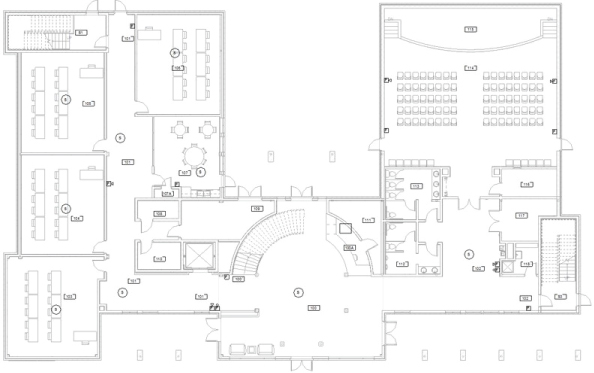
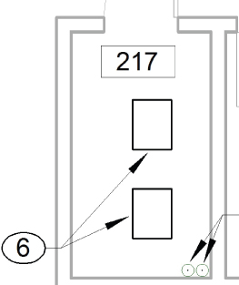
Because wiring is typically not shown on fire alarm drawings for the connectivity of the system, a fire alarm riser diagram is an important piece of the project. Although you cannot generate a riser diagram based on the devices placed into your model, you can use your model as a diagram, depending on the size and shape of the building. Figure 13.14 shows a floor plan with fire alarm devices placed throughout the building.
Figure 13.14 Sample fire alarm plan
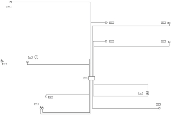
With the devices in place, the view can be duplicated and used as a diagram. Right-clicking the view in the Project Browser and selecting the Duplicate With Detailing option will give you an exact copy of the view, including any annotation and detail lines. Using the Visibility/Graphic Overrides settings to turn off the linked models leaves just the fire alarm devices and room numbers shown. Room numbers and other items that do not need to be shown can be hidden in the view. Detail lines can then be added to the view to show the connectivity of the system, as shown in Figure 13.15. Using this method creates a diagram that is showing the actual locations of the devices, so as changes are made to the design, you will need to edit only the detail lines in this view to update your diagram.
Figure 13.15 Fire alarm view with detail lines to be used as a riser diagram
This method has its drawbacks; the process would need to be repeated for every floor of a multistory building, resulting in several diagrams, so it is not a riser diagram in the true meaning of the term. It may also be difficult to use on a single-story building that is very large, where the devices are spread out, causing the diagram to be too large to justify the use of document space. However, if your project is the right size and shape, this method is a way to have your diagram tied directly to the model.
Fire Alarm Diagram Using Drafting Tools and Symbols
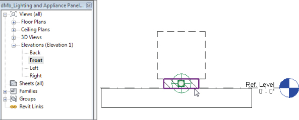
A more traditional approach would be to generate a diagram by using drafting tools and symbols. This can be done while still utilizing some of the model information such as levels and an elevation of the fire alarm control panel or equipment. You can create a detail section of your control panel, and then add symbols and detail lines to generate the riser diagram. In this section view, you can show the building levels and use constraints to maintain the relationship of your symbols to the levels so that, if changes are made, your diagram will update appropriately. The same symbol families that are nested into your fire alarm device families can be loaded into your project file for use in your diagram.
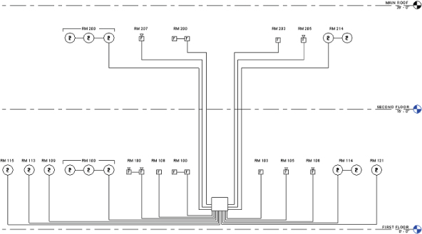
By utilizing the drafting tools available along with annotations and families, you can generate a fire alarm riser diagram without having to link in a CAD file and switch between applications to make changes. Figure 13.16 shows a simple example of how Revit MEP 2013 can be used for fire alarm diagrams.
Figure 13.16 Sample fire alarm riser diagram using detail lines, text, and symbols
Placing Devices and Equipment Connections
Certain elements within a power design do not require a physical component in the building model. They are points of connection to the electrical system, and are represented by a symbol to indicate to the electrical contractor where the connection is required. With Revit MEP 2013, you can represent these connection points with schematic symbols while building “intelligence” into the electrical model. Because the electrical information of a component is defined by its electrical connector, you can use symbols that contain connectors in order to account for the connections in your electrical model.
Equipment connections are the most common of these types of components. If you are linking an HVAC model into your project, you can use equipment connections that contain electrical information that matches the data in the component within the HVAC model. In this case, you would need to use an equipment connection family that contains an electrical connector. If you are working in a model that also contains the HVAC equipment, you can use an equipment connection symbol without an electrical connector (as long as the mechanical equipment has an electrical connector) and use the data from the HVAC equipment for your design.
You also have the option of using the Copy/Monitor tool to copy and monitor mechanical equipment families from a linked file. This is a good way to coordinate the location of equipment; however, you are relying on the mechanical model to be using the appropriate family with the correct electrical data. If the equipment in the mechanical model does not contain an electrical connector, you will need to monitor it with one that does. This means that you will have to load a similar mechanical equipment family that has an electrical connector into your project to be used for monitoring. Although this functionality is a step in the right direction toward coordinating mechanical and electrical components, it will require careful management of components used in the models and increased communication between consultants.
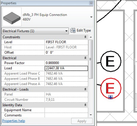
Figure 13.17 shows an equipment connection family used for an elevator. The elevator equipment has not been modeled, so an equipment connection family with an electrical connector is used. Because the equipment connection family is used for many types of equipment, the load is an instance parameter. This allows for adjustments to the load for each connection without having to create a new type within the family.
Figure 13.17 Equipment connection with a connector
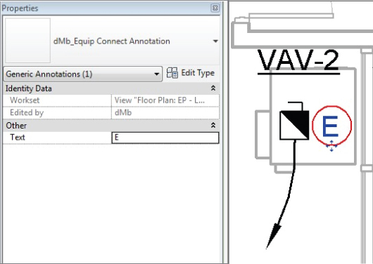
The mechanical equipment shown in Figure 13.18 is in the same model as the electrical components and has an electrical connector. In this case, a symbol without any electrical data is sufficient to represent the equipment connection.
Figure 13.18 Equipment connection symbol
In either case, the equipment connection can be attached to its associated model component by using face-hosted families. Constraints, such as locked alignment, can also be used, but only if both constrained elements are in the same model. Aligning and locking a component to a linked component will cause a constraint error if the linked component moves and the linked file is reloaded.
Another example of an electrical design component that does not have any physical geometry is a motor connection. A motor connection can be represented in the electrical model in the same way as an equipment connection. The electrical data for the motor can come from either the equipment family or the symbol family used to represent the equipment.
Disconnect Switches
Disconnect switches may not require model components, depending on their use and who is to provide them for construction. Certain types of equipment come with a means of disconnect built into them, while others require that a disconnect switch be provided in addition to the equipment.
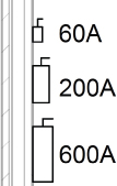
A disconnect switch that the electrical contractor is required to provide should be included as a model component in order to coordinate location and space requirements. Face-hosted families should be used because these types of disconnect switches may be mounted on walls or directly to the equipment that they serve. The disconnect switch family that comes with Revit MEP 2013 has several types based on voltage and rating. This family is found in the Electrical/MEP/Electric Power/Terminals folder of the library that installs with the software. The family is categorized as electrical equipment; therefore, using a symbol to represent this family is difficult because face-hosted electrical equipment does not contain the parameter to maintain annotation orientation. So each disconnect switch will display at its actual size based on the type chosen, as shown in Figure 13.19.
Figure 13.19 Disconnect switches in the building model
When a point of disconnect is required to be shown on the electrical plan but no equipment needs to be provided, a symbol can be used similar to the equipment connection symbol. There is no need for an electrical connector in your disconnect symbol family because a disconnect switch carries no load. However, wiring home runs for equipment are typically shown from the disconnect point, so you may want to include a connector point in your disconnect family for attaching wiring, or the wiring can be connected to the load source but drawn from the disconnect switch symbol.
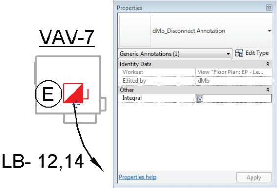
Figure 13.20 shows a point of disconnect for a variable air volume (VAV) box. The electrical connector is in the VAV family, so the point of disconnect is represented as a symbol. As with the equipment connection, the disconnect symbol can be constrained to the equipment to provide coordination with changes to the model as long as the equipment family is in the same file.
Figure 13.20 Disconnect symbol for equipment
Distribution Equipment and Transformers
Distribution equipment not only plays an important role in the function of a building, but it also is an important element of a building model. These types of components require space for accessibility. Using accurately-sized model components for distribution equipment allows you to coordinate early on with the architectural model for space requirements.
Transformers can be modeled at various sizes depending on their ratings and voltages. This works well if you want to show the actual size of the transformers on your power plans. If you choose to represent your transformers with a symbol, one can be added to your transformer family. It is not necessary to use face-hosted families for transformers, because they are typically located on the floor. An offset can be applied to wall-mounted transformers for placement at the proper height.
To place a transformer, do the following:
Figure 13.21 Distribution System drop-down for a transformer
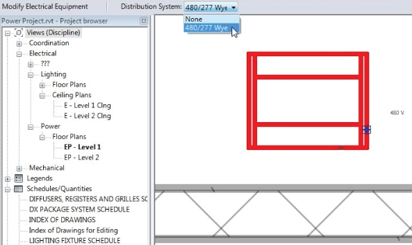
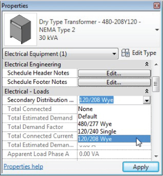
Figure 13.22 Secondary Distribution System parameter for a transformer
Switchboards
The various components that make up a switchboard are available in the Distribution folder within your library. Utility, metering, transformer, and circuit breaker sections are all available. Family types can be created within the families to meet the requirements of your design. If you do not know the exact equipment that will be used for your project, these families can act as placeholders until the equipment is chosen. Symbols can be used for various levels of model detail. The layout of switchboard sections can be used in elevation details if required.
To place a switchboard component, do the following:
Figure 13.23 Using the spacebar to rotate objects
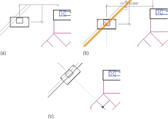
Figure 13.24 shows an example of a switchboard layout in (a) plan view and (b) section view.
Figure 13.24 Switchboard layout
The distribution system of a switchboard component can be defined after placement by selecting the element and using the Distribution System drop-down on the Options Bar, or by editing the instance properties in the Properties palette.
Panels
Electrical distribution panels are called many things by different users, such as panels, panelboards, or breaker boxes. In this book, we refer to them as panels and panelboards. The process for placing panels into your model is similar to placing other types of electrical equipment. You will want to use face-hosted panel families for coordination with architectural model changes. The panel families that come with Revit MEP 2013 are useful because they are easily customized to meet your company's standards for panel representation on construction documents.
Many companies use specific symbols to represent panels based on their voltage. The panel families that come with the software simply represent the size of the panel by displaying the box. You can add a detail component to them that contains a filled region that represents your standard. You must use a detail component because a nested annotation symbol will not work for face-hosted electrical equipment. The detail component must be placed in the Front or Back elevation view of the family in order to display when the panel is mounted to a vertical surface.
Figure 13.25 shows a panel family with a nested detail component family that is a filled region representing a 208-volt panel. This detail component is constrained to the parameters in the panel family and will change size with the panel.
Figure 13.25 Detail component in a panel family
Clearance space is an important issue when placing panels into your model. You could draw detail lines, or even model lines directly in your project view to represent the clearance spaces, but that would be difficult to manage when changes occur. Elements can be added to your panel families to represent clearances, not only for 2D plan views but also for the 3D model. This will allow you to check for interferences with objects that infiltrate that clearance space. In Figure 13.26, you can see a panel family that has line work to represent the clearance area in front of the panel for plan views, and solid extrusions that represent the 3D clearance areas.
Figure 13.26 Panel family with clearance elements
Using subcategories for the clearance elements gives you the ability to control their visibility in your model views. The 3D clearance space does not have to be visible in your model in order for Revit to detect that an object is interfering with it.
Customizing your Revit families to meet your company's standards makes them easier to use and can help utilize the model information for design decisions. To customize a panel with clearance space lines, do the following:
Assigning a distribution system to your panels is crucial to the intelligence in your electrical model. This will enable you to create circuits for devices and lighting fixtures as well as model the distribution system. The Distribution System drop-down is available on the Options Bar when you place a panel into your model.
Panels can be named using your naming standard by editing the Panel Name parameter. When using the panel families provided in your library or customized versions of them, you can control the size of a panel by establishing the number of poles. The Max #1 Pole Breakers parameter allows you to establish the number of poles available in the panel. An examination of the type parameters of one of these families reveals that the height of the panel is determined by the number of poles. The other parameters such as Mains, Enclosure, Modifications, and Short Circuit Rating that appear in the Electrical – Circuiting group of instance parameters are for information that will appear in the panel schedule. These parameters do not factor into the electrical characteristics of the panel or distribution system. They exist for reporting purposes only and have to be edited manually.
The Circuit Naming, Circuit Prefix Separator, and Circuit Prefix parameters allow you to control the naming of circuits that are fed from the panel. Because these are instance parameters, you can name circuits differently for each panel if necessary. You do not need to use these parameters in order to tag your circuits.
Other Equipment
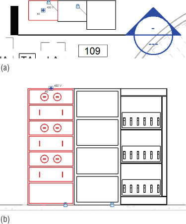
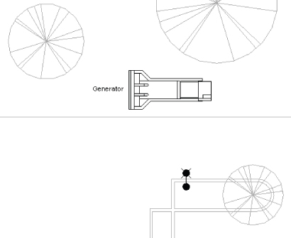
Component families can be used to represent any type of electrical equipment required in your Revit project. Items such as generators, automatic transfer switches, starters, and variable frequency drives are available in the library. Figure 13.27 shows a diesel generator on the site plan of a project. The generator family displays differently depending on the Detail Level setting of the view. In Coarse detail, the generator displays as a simple box, while in Fine detail the shape of the equipment is visible.
Figure 13.27 Generator in a Revit model
For telephone device systems, you can use a family to represent the punch-down blocks that act as the termination point for the telephone wiring within the building. This would allow you to keep track of your telephone devices in different areas of the building. It is best to use a face-hosted family for this type of equipment because it is typically wall mounted. If your equipment family behavior is set to Other Panel, the Create Panel Schedules button appears on the Modify | Electrical Equipment contextual tab. You can create a panel schedule template that can be used for communications equipment to show connected devices. See Chapter 7, “Schedules,” for information on creating panel schedules.
Server racks or audio equipment racks can be either wall mounted or free-standing equipment, so nonhosted families can be used to accommodate either condition. A server rack family can be used as the equipment for your devices with data connections, and an audio equipment rack family can be used for devices with communications connectors. Figure 13.28 shows server racks placed in the center of a room to allow for the required clearances for the equipment.
Figure 13.28 Server racks
Creating Power Distribution Systems
Having electrical equipment components in your Revit project enables you to coordinate space requirements and interferences with other building systems, but it also allows you to build intelligence into the model by establishing distribution systems. Establishing the distributive relationship between electrical components gives you the ability to keep track of loads from the branch circuit panels all the way to the main electrical equipment.
This is where the importance of assigning a distribution system to your electrical power equipment as it is placed comes into play. With the equipment in place, you can easily create the relationship from component to component. You can start at any component and connect to related equipment upstream. Since you will be assigning the equipment that feeds a component, it is best to start at the branch circuit panels and work your way upstream through the system. No wiring or conduit needs to be modeled in order to establish the electrical connection between two distribution components.
To create a distribution system, follow this general process:
Figure 13.29 Selecting a Panel for a distribution system
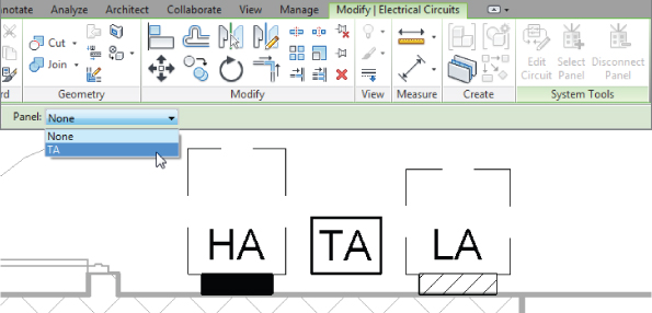
Figure 13.30 Using the Tab key to identify a circuit
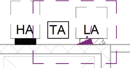
Figure 13.31 Selecting a Panel for a distribution system
You can repeat this process for equipment as far upstream as you want to keep track of load information. Obviously, you aren't going to model the utility company's equipment or the local power plant, so when you get to the last component, you will not have any panel or equipment to select for its circuit. It is still recommended that you create a circuit for this equipment, because you will be able to access the properties of the circuit and establish feeder information.
Power Diagrams
The most common way to communicate a distribution system is by a riser or one-line diagram. This schematic representation displays the connection relationships between electrical distribution equipment in a clear and easily readable manner (unless the project is large and complicated, in which case readability becomes debatable).
One of the first questions that comes up about using Revit MEP for electrical design is whether it can automatically create a power riser diagram from the components within the model. Unfortunately, at this point, it does not have that capability. This does not mean that you cannot create a diagram directly in your project. The drafting tools within Revit MEP 2013 provide you with all the tools you need to create your diagrams or, if you are more comfortable using a CAD application for drafting tasks, you can link a CAD-generated diagram into your project.
Tips for Creating Power Diagrams
It is best to have a library of commonly used symbols to facilitate quick and easy creation of your power diagram. Symbols for items such as panels, transformers, grounding components, and generators can easily be created and stored for use on future projects. These symbols can contain parameters that make it easy for you to schedule and manage changes to the component data.
Consider creating a detail section view of your switchboard equipment or main distribution panel as the starting point for your diagram. In this view, you can turn off any linked files and worksets that do not need to be shown, leaving you with an elevation view of your equipment and the project levels, which are typically shown on riser diagrams.
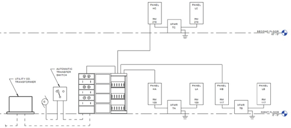
Symbols can then be placed into this detail view to represent the electrical distribution equipment. Detail lines can be drawn in the view to represent the connection between elements. You can use the power of Revit to create line types specific to your needs for electrical diagrams to increase your efficiency when drafting. Although the symbols and line work are not tied to the model elements that they represent, you are able to coordinate data required in both places without having to switch between applications. Figure 13.32 shows an example of a power diagram created by using an elevation view of the switchboard, symbols, text, and detail lines.
Figure 13.32 Power diagram created in Revit
Temporary dimensions and alignment lines make drafting and editing diagrams in Revit MEP easy and, with a little practice, you can become proficient with the available tools. We are all looking forward to the day when power diagrams will be generated automatically from the model, but until then, you have the tools necessary to create them.
Modeling Conduit and Cable Tray
The tools for modeling conduit and cable tray were introduced in Revit MEP 2011. With them, you can create conduit and cable tray runs within your project model for coordination with other system components. Conduit and cable tray are system families for which you can define different types. Parameters can be used for tagging and scheduling these families to keep track of quantities and materials if desired. The techniques for modeling conduit and cable tray are similar to those for placing ductwork or pipe. It is not likely that you will model all of the conduit required for your project, so the size limit for conduit that will be modeled should be made clear early on in the project.
There are two styles of system families for conduit and cable tray. You can create runs that utilize fittings or runs that do not. If you want to model a run of conduit that will be bent to change direction, you would use the style without fittings. This allows you to determine the length of the run and does not add components to the model that would not exist in the construction.
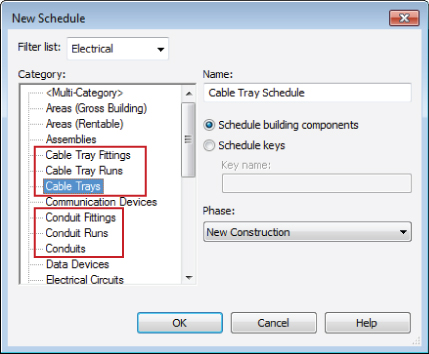
Because there are two different styles for conduit and cable tray, there are also two schedule types that can be created. The Cable Tray Runs category in the New Schedule dialog box is for the cable tray style without fittings. This schedule style contains parameters for reporting the total length of a run, including any change in direction. The Cable Trays or Cable Tray Fittings schedule style is used for the cable tray style that utilizes fittings. This type of schedule can be used to report data about the individual pieces that make up a run of cable tray. The same schedule types are available for conduit, as shown in Figure 13.33.
Figure 13.33 Conduit and cable tray schedule categories
When you model a run of cable tray or conduit by using the style without fittings, it does not mean that no fittings exist in the run. You still have to define what fittings will be used to transition or change direction, but the length of the fittings will be included in the total length of the run. Figure 13.34 shows the fittings assigned to a cable tray style without fittings.
Figure 13.34 Fittings assigned to a cable tray family
A fitting family must be assigned to each parameter in order to model a run of conduit or cable tray; even if you are not modeling a condition that requires a tee, you still must have a fitting family assigned for tees. It may seem counterintuitive to assign fittings to a system family without fittings, but it is necessary in order for the runs to be modeled. When you model a run without fittings, the fittings used will have a value of Bend for their Bend or Fitting parameter. For runs modeled using fittings, the parameter value will be Fitting. This can be useful information when scheduling conduit or cable tray.
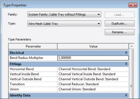
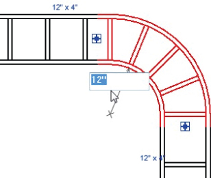
The bend radius for cable tray elbows is set to the width of the cable tray by default. The Bend Radius Multiplier parameter can be used to define a bend radius for different types within the system family. The bend radius of an elbow can be modified directly in the model by selecting the fitting and editing the temporary radius dimension that appears, as shown in Figure 13.35. The bend radius for conduit elbows is determined by a lookup table defined in the fitting family.
Figure 13.35 Editing a cable tray bend radius
Conduit will display as a single line in views set to Coarse or Medium detail level. Cable tray displays as a single line in views set to Coarse detail level. In views set to Medium detail level, cable tray will display as two-line geometry. Ladder-type cable tray will display as a ladder in views set to Fine detail level.
Defining Electrical Settings
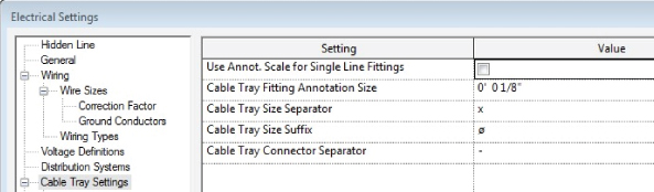
Conduit and cable tray settings and sizes can be defined in the Electrical Settings dialog box, which is accessed via the MEP Settings button on the Manage tab. The general settings are used to define the visibility behavior of conduit or cable tray when shown as single-line graphics, as shown in Figure 13.36. A suffix and separator can be defined for tagging.
Figure 13.36 Cable Tray general settings
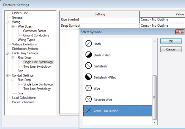
Rise/Drop graphics can be defined for both cable tray and conduit. Clicking the Value cell activates the Select Symbol dialog box, which allows you to choose a graphic representation for a conduit or cable tray rise or drop, as shown in Figure 13.37. Graphics can be defined for both single-line and two-line representation. You cannot create your own symbols to use for this representation.
Figure 13.37 Rise/Drop symbol options
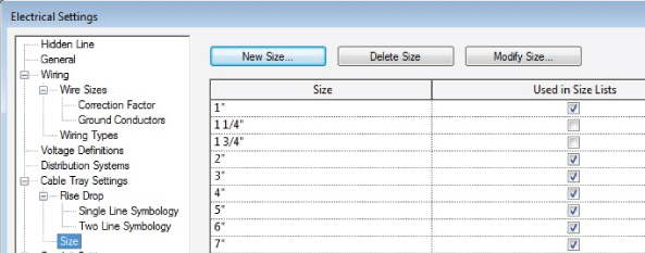
The Size settings for cable tray are very simple. You can input sizes available for cable tray and also choose whether certain sizes are available for use in your project by selecting the box in the Used In Size Lists column, as shown in Figure 13.38.
Figure 13.38 Cable tray Size settings
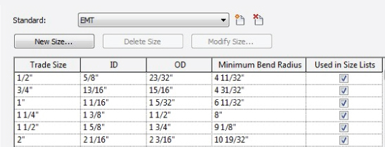
The Size settings for conduit are more detailed because of the difference in dimensions for various conduit materials. Sizes and a minimum bend radius can be defined for each conduit material type, as shown in Figure 13.39.
Figure 13.39 Conduit size settings
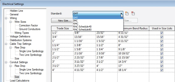
You can create additional settings for materials by clicking the Add Standard button next to the drop-down at the top of the dialog box. A few standards are predefined, and you can use them as the base settings for creating custom standards. Figure 13.40 shows the predefined conduit standards available in Revit MEP 2013.
Figure 13.40 Conduit standards for size settings
Whether or not a conduit size is available for use in your projects is determined by selecting or deselecting the check box in the Used In Size Lists column. Be sure to set your Project Units settings to coincide with the available sizes. For example, if you set the Rounding value of the Conduit Size units to the nearest 1/2″, then even if the 1 1/4″ conduit size in the Electrical Settings dialog box is set to be available in size lists, it will not display in the list. If you are using metric units, the Rounding setting must match the number of decimal places of the conduit or cable tray sizes in order for a conduit or cable tray size to display in the available sizes list.
The settings for conduit and cable tray that you use most often should be established in your project templates so that you can begin modeling right away. The settings can be modified to meet any unique requirements of a project after the project file has been created.
Placing Conduit in a Model
Once you have defined the desired settings for conduit and cable tray, you can begin modeling in your projects. To model a run of conduit, click the Conduit button on the Systems tab. Choose the desired style (with or without fittings) from the Type Selector in the Properties palette. The Diameter drop-down on the Options Bar displays the list of available sizes based on the settings defined in the Electrical Settings and Project Units dialog boxes. The Offset drop-down on the Options Bar determines the elevation of the conduit above the level of the currently active view. Click in the drawing area to start the run of conduit. Move your mouse pointer in the desired direction, and click to finish the run or change direction.
The Modify | Place Conduit contextual tab also contains tools for placement. The Justification button allows you to define the point along the conduit that determines its elevation. If you choose to draw conduit with a vertical justification at the middle and the horizontal justification at the center, then the value given for the offset of the conduit will be directly in the center of the conduit. These settings allow you to draw conduit from the top, middle, or bottom to coordinate elevations with other model elements. The elevation of a conduit can be changed after it is drawn by selecting the conduit and editing the value in the Offset drop-down on the Options Bar or the Offset parameter in the Properties palette.
The Automatically Connect button on the contextual tab is set by default. This setting means that a fitting will be automatically placed when one conduit touches another in the model. The Tag On Placement button can be selected to tag conduit automatically as it is drawn. A conduit tag must be loaded into the project, and settings for the tag placement are available on the Options Bar.
The Inherit Elevation button allows you to set the elevation of the conduit you are modeling to match that of an object to which you are snapping. The Inherit Size button will set your conduit size to match that of an object to which you are snapping. You can use the spacebar to inherit both the elevation and size of an object to which you are snapping.
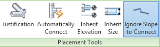
You can change the elevation in the midst of modeling a run by changing the Offset value in the drop-down and then continuing the run. Revit will automatically insert the proper fittings and vertical conduit to transition to the new elevation. The Ignore Slope To Connect button, shown in Figure 13.41, allows you to connect conduit from one elevation to another without a vertical conduit. When you start drawing conduit at an elevation, you can turn this feature on and connect to conduit at a different elevation. The run of conduit will be modeled directly to the point of connection, with whatever slope is required to make the connection. This is more commonly used for sloped plumbing pipes, but is also available for conduit.
Figure 13.41 Conduit placement options
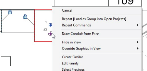
To connect conduit to equipment or a device, the object must have a conduit connector. When you select the object, you can right-click the conduit connector grip and choose the option to draw conduit from the connector, as shown in Figure 13.42. This connector is defined as a face connector, which means that conduit can be connected anywhere on the face of the equipment. It also means that multiple conduits can be connected to the face.
Figure 13.42 Drawing conduit from a connector
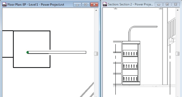
Selecting this type of connector allows you to choose the position of the connection prior to drawing the conduit. The connection point can be dragged to any location on the face, or you can edit the temporary dimensions to locate the connection point. Once you have determined the location, click the Finish Connection button on the Surface Connection contextual tab. You can now draw the conduit from the connector. Be sure to assign an appropriate Offset value prior to drawing. Once the conduit has been drawn, you must disconnect it from the connector point on the equipment if you want to move the location of the connection. Figure 13.43 shows plan and section views of conduit drawn from the top of an electrical equipment object.
Figure 13.43 Conduit drawn in a model
Individual connectors have a static location that can be modified only by editing the family. Only one conduit can be drawn from this type of connector.
Revit MEP 2013 has tools that allow you to model parallel runs of conduit. This is very useful for modeling banks of conduit runs quickly, without having to model several runs or make copies.
To model parallel runs of conduit, you need to start with a single run. Once the run is complete, you can click the Parallel Conduits button on the Electrical panel of the Systems tab. This activates the Parallel Conduits contextual tab, which contains settings for the parallel runs, as shown in Figure 13.44.
Figure 13.44 Options for parallel conduits
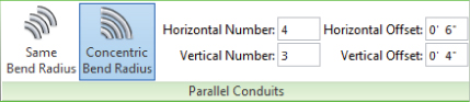
You can choose for the conduits to all have the same bend radius, or to use concentric bends, which take up less space and provide a more uniform layout. The Offset fields allow you to assign the spacing both horizontally and vertically between the runs. A positive value for the vertical offset will place runs above the original, while a negative value will place them below.
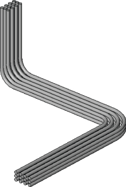
After you have established the desired settings, place your cursor over one of the conduits or fittings in the original run. You will see a reference line or lines indicating the side to which the parallel runs will be placed. You can move your cursor slightly to change sides. Press the Tab key to highlight the entire run, and then click to create the parallel runs. Figure 13.45 shows a simple example of parallel runs that were created by using the Parallel Conduits tool.
Figure 13.45 Parallel Conduit runs
Placing Cable Tray in a Model
The process for modeling cable tray is the same as for conduit. There is a drop-down on the Options Bar for the Width and Height settings of the cable tray, as defined in the Electrical Settings dialog box. Cable tray can be connected to equipment or devices that have cable tray connectors. Cable tray connectors have a static location and cannot be moved along the face of the family without editing the family.
You can connect conduit to cable tray by snapping your mouse pointer from the cable tray edge when drawing the conduit. The conduit connects to the center of the cable tray so, if you are using the Fine detail level, setting the center line of the conduit will display beyond the connected edge of the cable tray.
Figure 13.46 Conduit connected to cable tray
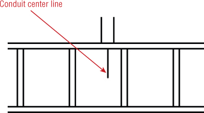
You can remedy this by turning off the center line of conduit in the Visibility/Graphic Overrides settings of the view.
Creating Family Types
You can create unique family types for conduit and cable tray system families. Select a conduit or cable tray in the model, and click the Edit Type button in the Properties palette. Or you can double-click a conduit or cable tray family in the Project Browser to access the Type Properties dialog box for that family. Click the Duplicate button in the dialog box to create a new family type. Give the new family type a descriptive name that defines the type. You can then assign fittings or parameter values that make the type unique from other types within the family. The newly-created family type will then be available in the Type Selector when placing conduit or cable tray.
The types of conduit and cable tray that you most commonly use should be defined in your project templates for easy access. Additional fittings can be loaded to create unique family types if the project requires.
The Bottom Line
Place power and systems devices into your model.
Creating electrical plans that are correct not only in the model but also on construction documents can be achieved with Revit MEP 2013.
Master It
Having flexibility in the relationship between model components and the symbols that represent them is important to create an accurate model and construction documents. Is it possible to show a receptacle and its associated symbol in slightly different locations to convey the design intent properly on construction documents? If so, how?
Place equipment and connections.
Electrical equipment often requires clearance space for access and maintenance. Modeling equipment in your Revit project allows you to coordinate clearance space requirements.
Master It
Interference between model components can be detected by finding components that occupy the same space. Explain how you can determine whether an object interferes with the clearance space of an electrical equipment component.
Create distribution systems.
Proper setup of distribution systems is the backbone of the intelligence of your electrical design. It helps you track the computable data within your project.
Master It
Because your project may contain multiple distribution system types, explain the importance of assigning distribution systems to your electrical equipment and naming your equipment.
Model conduit and cable tray.
Large conduit and cable tray runs are a serious coordination issue in building designs. Revit MEP 2013 has tools that allow you to model conduit and cable tray in order to coordinate with other model components.
Master It
Conduit and cable trays can be modeled with two different styles. One style uses fittings, and one does not. Does this mean that no fittings need to be assigned to the style that does not use fittings? Explain how this affects the scheduling of the components.