
Chapter 11
Mechanical Piping
Mechanical piping is the lifeblood of a heating/cooling system. Incorrect piping can lead to problems in the field, and locating the pipes may take months. There are simple two-pipe systems and more-complex multipipe systems. When using Autodesk® Revit® MEP 2013 to lay out your systems, you will be able to easily see your routing options and even calculate the total volume of fluid in your system.
In this chapter, you will learn to do the following:
- Adjust the mechanical pipe settings
- Select the best pipe routing options for your project
- Adjust pipe fittings
- Adjust the visibility of pipes
Mechanical Pipe Settings
When setting up the mechanical piping to route, you will want to apply the proper pipe material. The purpose of this is to provide a more accurate layout by showing the correct pipe sizes and fittings for that system. You will have to adjust several areas to set this up properly. Most important are the Piping Systems and Pipe Types settings. You can also adjust pipe segments and sizes, as well as the fluids table as needed. Each is described here in more detail. After you set up these areas, you can then concentrate on the autorouting or manual routing of pipe.
Piping Systems
These are the pipe system types that are hard-coded into Revit projects and families. You have the option of creating new types, changing the names, and customizing the object styles for these system families within your project.
Pipe Types
This is where choices can be made regarding the fittings and material for each pipe type. As you model with a selected type, these fittings and parameters will automatically populate the pipe system and the model. The pipe fittings must be loaded into the project in order to select them in the Type Properties dialog box.
Pipe Segments and Sizes
These are set by choosing Mechanical Settings ⇒ Segments And Sizes. You can select or duplicate a pipe segment, rename it, and apply the piping specifications for material, schedule/type, common sizes, and roughness of pipe walls.
Fluids Table
You access the fluids table by choosing Mechanical Settings ⇒ Fluids. You can duplicate, rename, and adjust the fluid type as well as its viscosity, temperature, and density.
Slopes Table
From the slopes table you can preset the pipe slopes that will be used for the project. You access the slopes table by choosing Mechanical Settings ⇒ Slopes. The list of the slopes will be available for you to select from, when you are drawing pipe with slope.
Creating Piping Systems
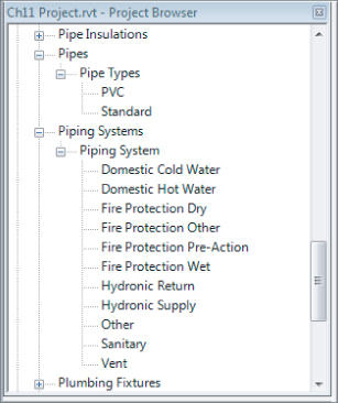
Piping systems are essential part of designing piping layouts in Revit MEP 2013. They allow you to separate pipes from one another based on the function they are serving, the color and line pattern they should be displayed with, the fluid type they carry, and so on. The Piping Systems Properties can be accessed and customized from Project Browser ⇒ Families ⇒ Piping Systems (see Figure 11.1). You can see the piping systems required in all projects in the Project Browser:
- Domestic piping systems (covered in other chapters):
- Domestic Cold Water
- Domestic Hot Water
- Sanitary
- Vent
- Fire protection piping systems (covered in other chapters):
- Fire Protection Dry
- Fire Protection Other
- Fire Protection Pre-Action
- Fire Protection Wet
- Other (You can't use any calculations for this option, therefore this option is appropriate only for systems that don't require calculations.)
- Mechanical piping systems:
- Hydronic Return
- Hydronic Supply
Figure 11.1 Renaming pipe types
Each of these items is what we call a system classification. System classifications are hard-coded in Revit and you can't create new ones. However, you can create additional system types by right-clicking any of the existing piping systems and selecting Duplicate. When duplicating piping systems, it is important to determine what the system classification should be and select an existing piping system that is already assigned to that system classification. Once you create your piping system and realize that the system classification is incorrect, there is nothing you can do but delete it and start over with another one that has the correct system classification. There are a number of limitations with the system classifications; you are not allowed to change the system classification of piping systems or create or delete any system classifications. In addition, you must have at least one piping system for each of the 11 system classifications, and you cannot delete any of them even if you don't need them for your project.
Each piping system can be assigned its own project-wide graphic override. This, combined with the ability to assign a segment of pipe to any of these piping systems without attaching it to a fixture or equipment, lets you improve the documentation produced earlier in the design process, when equipment families have not been yet been built.
One important drawback is that, because the line type settings for piping systems are applied in all views, the common dashed-line patterns that are used with single-line pipe display (coarse or medium detail) will also dash the double-line pipe views (fine detail). For this reason, you can apply view filters to override any piping system graphic overrides. View filters are discussed in more detail later in this chapter in the “Defining System Visibilities through Filters” section.
Creating Pipe Types
To understand Revit MEP pipe types, imagine them from the perspective of the installer. The pipe type is related to the material and style of fitting used. For instance, both chilled and hot water mechanical pipes, 3′ (914 mm) in diameter and under, are commonly constructed from copper with soldered or brazed sweat joint fittings. This should be the basis of your pipe type.
To modify and create new pipe types, in the Project Browser choose Families ⇒ Pipes ⇒ Pipe Types and then right-click the Standard type. Select Duplicate. This will create the additional pipe types you will need for your project. Next, right-click the duplicated pipe types and rename them to the pipe types you require. It is preferable to rename them to the pipe material type selected under the Pipe Segment. You can find out or change the pipe material under the Pipe Segment selection by right clicking over the pipe type and going to its Type Properties ⇒ Routing Preferences.
Now that you have your pipe types created, you will want to change some of the parameter options. First, right-click the pipe type you want to edit and select Type Properties. This opens the Pipe Type parameters. With regard to careful space planning, the accurate selection of fittings is the most important and most time-consuming task when setting up your pipe types.
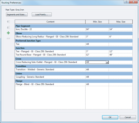
Revit MEP 2013 introduces and improved pipe Type Properties dialog box with Routing Preferences (see Figure 11.2). In the past you could assign only one elbow or tee family per pipe type; now you have the option to set different fittings based on the pipe size you are drawing (see Figure 11.3).
Figure 11.2 Type Properties dialog
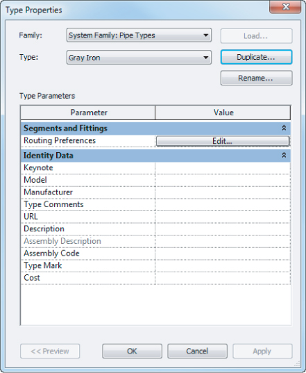
Figure 11.3 Routing Preferences dialog
Under the Identity Data parameters group, the following parameters are available: Keynote, Model, Manufacturer, Type Comments, URL, Description, Assembly Description, Assembly Code, Type Mark, and Cost. If you have a certain manufacturer, model, or other special note that you want to denote on the plans, you can use these settings to describe your pipe type further (see Figure 11.2).
Selecting Fittings for Routing Preferences
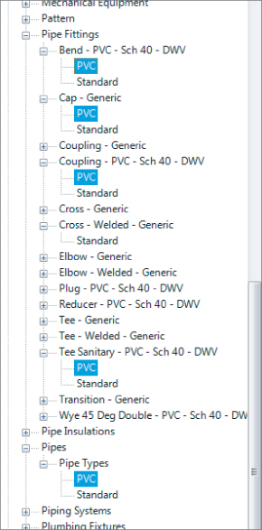
Before you can adjust the Routing Preferences, you need to create the fittings that will go with your system pipe types. To accomplish this, open the Project Browser and choose Families ⇒ Pipe Fittings. Then select the fittings that will be required for your Pipe Type parameters. You can either load the appropriate family from the Autodesk library or other source or right-click each of the family fittings and duplicate standard generic Elbow, Cross, Coupling, Tee, and Transition fittings. After duplicating or loading each desired fitting, rename them to the associated material of each pipe that you previously duplicated to create your pipe types (see Figure 11.4).
Figure 11.4 Duplicating and renaming fittings to match pipe types
One noteworthy option that is missing from the Fitting parameters is a pipe spud. To date, Autodesk has not included this pipe fitting family with its content. However, several pipe spud families can be downloaded from the Internet. If you would like to use one in your Steel-Welded pipe type, you first have to load the family into your project. Next, duplicate your pipe type and rename it Steel-Welded-Tap. It is critical that you have a separate pipe type because the Preferred Junction Type fitting parameter is set here. Change it to Tap, set the Tee to None, and the Tap parameter to Pipe Spud (the name of the family you have downloaded or created). Now you will be able to easily choose whether to model pipe with tee fittings by selecting the pipe type Steel-Welded, or model with spud-style tap fittings by selecting Steel-Welded-Tap.
Choosing Pipe Materials and Sizes
To access the pipe material settings, choose Systems ⇒ Plumbing & Piping and then select the small arrow in the lower-right corner of the ribbon. This opens the Mechanical Settings dialog box. (Alternatively, choose Manage ⇒ MEP Settings ⇒ Mechanical Settings.) Next, choose Pipe Settings ⇒ Segments And Sizes. If you want to create a new pipe segment, you can duplicate an existing pipe segment and rename it to the new pipe segment required (see Figure 11.5). From here you can also change the Roughness setting and Segment Description or create a new pipe size.
Figure 11.5 Creating new Segments And Sizes
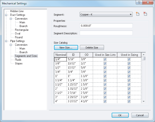
Adjusting the Pipe Sizing Table
If you want to adjust the sizing table, choose Systems ⇒ Plumbing & Piping, and select the small arrow in the lower-right corner of the panel to open the Mechanical Settings dialog box. Next, choose Pipe Settings ⇒ Segments And Sizes. You can duplicate the schedule of pipe and apply the pipe wall thickness as required. You can also select and deselect the piping sizes to match your design standards (see Figure 11.5).
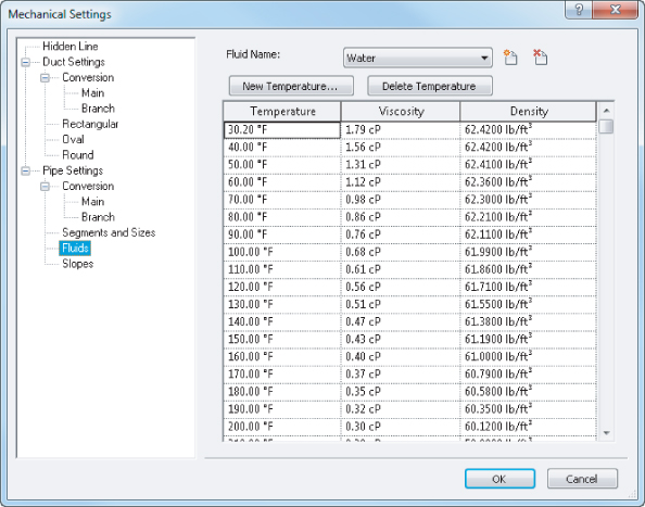
Using the Fluids Table
Revit MEP will use the fluids table when you are sizing your pipes or determining pressure drop. You can add information concerning temperature, viscosity, and density to the fluids table. To do this, choose Systems ⇒ Plumbing & Piping, and select the small arrow in the lower-right corner of the panel to open the Mechanical Settings dialog box. Next, choose Pipe Settings ⇒ Fluids. Then duplicate one of the fluid categories that is close to the one you need, and modify it as required (see Figure 11.6).
Figure 11.6 Fluids table settings
Pipe Routing Options
The size of a mechanical piping model can grow quite large because of the amount of fluids constantly transferred, so it is very important that routing is closely coordinated. Using Revit MEP 2013, you can improve visual coordination with color-coded systems and use interference checking to monitor conflicts with cable trays or sprinkler piping. Two routing options are available when you set out to design your piping model: the autoroute option and the manual routing option. Both are described in this section.
In smaller systems, the autoroute feature may be beneficial. However, in most circumstances, manual routing will be of greater benefit to you. This is because a good design engineer can optimize a system with regard to construction of pipe and coordination with other trades, especially structure.
Automatic Pipe Routing
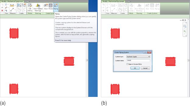
Ideally, you have everything set up in your pipe types before you begin routing piping. To start automatic pipe routing, first assign your equipment to a piping system. Select two or more pieces of mechanical equipment and, from the Modify | Mechanical Equipment tab, click Create Systems ⇒ Piping (see Figure 11.7a) and then name your piping system (see Figure 11.7b).
Figure 11.7 Create your piping system.
Next, select any piece of equipment assigned to the system and click the Generate Layout button. You have four options for generating the layout: Network, Perimeter, Intersections, and Custom. Each one has several routing solutions from which you can choose, consisting of a main (blue) and branches (green):
Network
This solution creates a bounding box around the components selected for the piping system and then bases several solutions on a main segment along the center line of the bounding box with branches coming from the main segment.
Perimeter
This solution creates a bounding box around the components selected for the system and proposes several potential routing solutions. You can specify the Inset value that determines the offset between the bounding box and the components. Inset is available only when the Perimeter option is selected.
Intersections
This solution bases the potential routing on a pair of imaginary lines extending from each connector for the components in the system. Perpendicular lines extend from the connectors. There are potential junctions in the proposed solutions along the shortest paths, where the lines from the components intersect.
Custom
This solution becomes available after you begin to modify any of the other solutions.
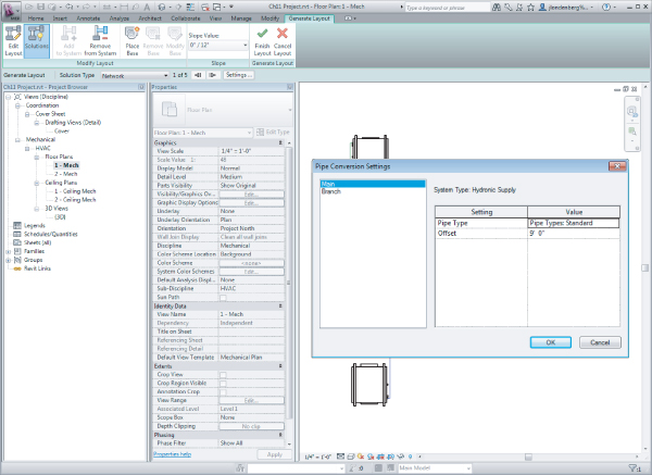
The autoroute feature is most useful in small, simple layouts. Usually, the greatest benefit comes from using the autoroute pipe as a starting point and finishing with additional manual layout. You can set the mounting height by clicking the Settings button from the Options tab and inputting a new offset. Make sure to define the offset for both Main and Branch (see Figure 11.8).
Figure 11.8 Autoroute piping layout
Manual Pipe Routing
Manual routing of piping is the next method. When routing, manually start the piping run at the elevation that you know will most likely be out of the way of other disciplines. Use the following steps to set up and place mechanical equipment, create a hydronic supply and return, and manually route pipe to all pieces of equipment:
Figure 11.9 Linking the Revit model, Auto - Origin To Origin
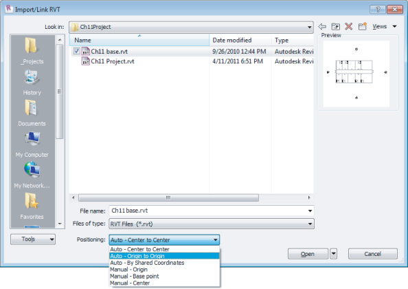
Figure 11.10 Water source heat pumps
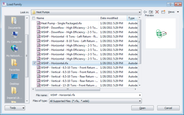
Figure 11.11 Verifying the offset for the correct elevation
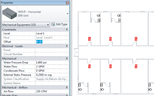
Figure 11.12 Placing mechanical equipment
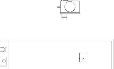
Figure 11.13 Placing the pump in the mechanical room
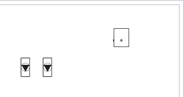
Figure 11.14 Routing pipe mains
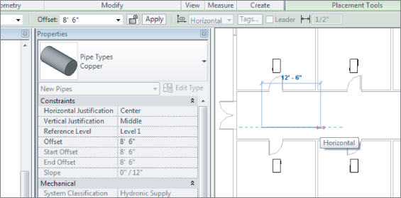
Figure 11.15 Creating mechanical piping systems
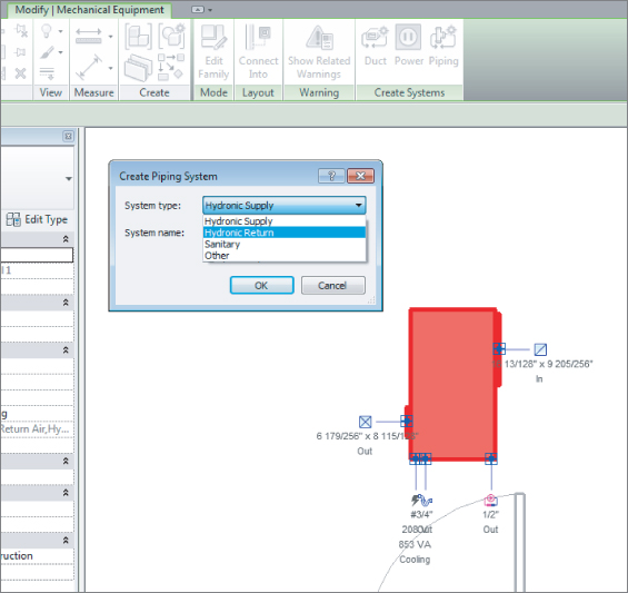
Figure 11.16 Adding equipment to systems
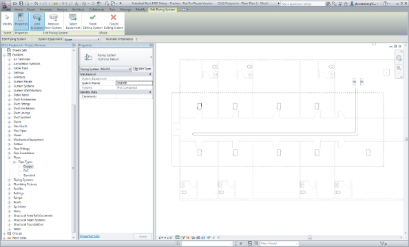
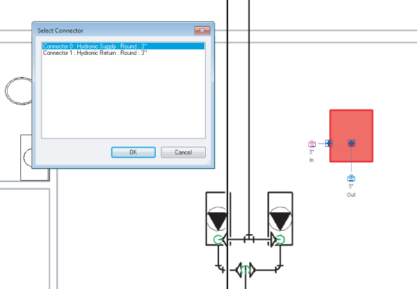
Figure 11.17 Selecting Connect Into
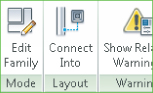
Figure 11.18 Using Connect Into
Pipe Fittings
Without fittings, piping would not be worth a whole lot. Fittings help shut off the flow, help regulate temperature, and help save lives. In Revit, most fitting families have the following functions:
End Cap
These can be placed only at the end of pipe.
Tee, Tap, Wye, or Cross
These can be placed anywhere along pipe runs.
Transitions, Couplings, or Unions
These can be placed only at the end of pipe. They are used to join a smaller, larger, or same-sized pipe.
Flange
These can be placed at the end of pipe or face to face with another flange.
Using Pipe Fitting Controls
Understanding pipe fitting controls can really make life easier if you are routing a lot of piping. When you are laying out your piping, turn 90 degrees to create an elbow. If you click the elbow, you will notice a plus (+) sign. If you click that sign, it will change from an elbow to a tee, allowing you to add more piping and continue your pipe routing. If you click the minus (-) sign, it will downgrade the fitting. When you see the ![]() symbol on a fitting, it allows you to rotate the fitting, and the
symbol on a fitting, it allows you to rotate the fitting, and the ![]() symbol allows you to flip the fitting.
symbol allows you to flip the fitting.
Placing Fittings
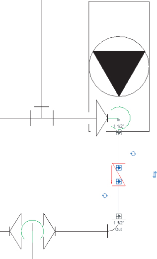
When you need to add valves to your piping, select the System tab and then select Pipe Accessory. Use the Type Selector to select the type of valve you want to use. Most valves are break into types, so you can place them into a pipe run, and they will break into the piping, maintaining connections at either end (see Figure 11.19).
Figure 11.19 Fitting breaks into a piping system
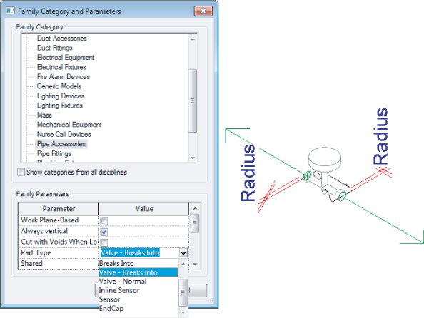
For most logical family categories, you can set this break into functionality in the Family Editor; choose Create ⇒ Properties ⇒ Family Category And Parameters (see Figure 11.20).
Figure 11.20 Fitting breaks into the definition
Defining Systems Visibility through Filters
Revit MEP 2013 will automatically create the logical piping systems for you when you lay out pipes, even when pipes are not connected to equipment. When drawing pipes you will need to specify what system type it belongs to. The system type will define the line weight, line type, color, and system abbreviation. The system abbreviation can be used to define what system will appear on what sheet via filters. This will help you hide the mechanical pipes in the plumbing views and vice versa.
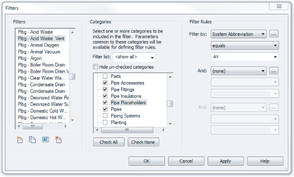
Establishing a good naming convention for the filters is very important, because that would be the order you see them in your Properties palette when drawing pipes. The default examples of filters and their settings are not going to get you too far with your projects. I recommend that you take your time and come up with a complete list of systems that your company uses and create them as system types and filters in Revit MEP. Organizing all of them in Microsoft Excel can be very beneficial! (See Figure 11.21.) Notice that the Filter By setting is set to System Abbreviation Equals AV. Bear in mind that the parameter System Abbreviation was not available prior to Revit MEP 2012 and the settings would be different for those projects and templates. To create new filters simply click the New button in the lower-left corner.
Figure 11.21 Sample filters and their settings
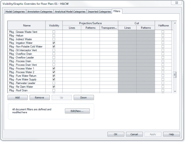
Once the filters have been created, go into each view where you want the different disciplines to show up and type VG to bring up the Visibility/Graphic Overrides dialog box. Click the Filters tab, and add the newly created filters. Using the Visibility check boxes on the Filters tab, you can define the systems to be visible in that view. In the past filters were used to also define color, line patterns, and in some cases line weights. Since Revit MEP 2012 the recommended place to control those is in the system type. This way, those settings will be global rather than per view. However, the filters would still be managed and would control what system is visible in what view (see Figure 11.22).
Figure 11.22 Adjusting visibility of pipe and duct systems through filters
Now that your plans are coordinated and displaying the way you require, you are well on your way to completing your documentation.
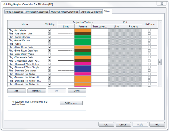
Earlier we said that colors, line types, and line weights should be controlled via the system type. Well, every rule has its exception, and here is a great example for this. When you control the colors and line patterns of your systems in the 3D views, it will color the contour of the pipe, making the pipes hard to see. Instead of going that route, you could override those in the filters with a solid pattern; this way, your 3D views would be a lot easier to view and understand (see Figure 11.23 and Figure 11.24).
Figure 11.23 The same model displayed without filter overrides (on the left) and with overrides (to the right)
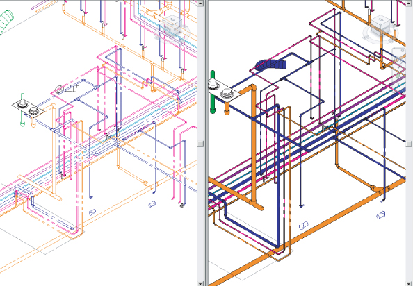
Figure 11.24 Applying filter overrides for 3D views
The Bottom Line
Adjust the mechanical pipe settings.
Making sure that the mechanical piping settings are properly set up is crucial to the beginning of any project.
Master It
A designer has just been asked to model a mechanical piping layout, and the engineer wants to make sure the designer will be able to account for the piping material used in the layout. What steps must the designer take to the complete this request?
Select the best pipe routing options for your project.
When using Revit MEP 2013 for your mechanical layouts, you must understand the functions of automatic pipe routing and manual pipe routing. After mastering these functions, you can lay out any type of piping system.
Master It
The engineer has just come back from a meeting with the owner and architect, and it has been decided that there will be a heated-water system and a chilled-water system rather than a two-pipe hydronic system. How would you modify your hydronic layout to accommodate the change?
Adjust pipe fittings.
Pipe fittings are needed in systems to make the systems function properly and to produce documentation for construction. Being able to add or modify fittings can increase productivity.
Master It
You have printed a check set for review and have noticed that there are no shutoff valves. Now, you need to load the shutoff family. In what directory should you look for pipe fittings?
Adjust the visibility of pipes.
Being able to adjust the visibility of pipes gives the mechanical designer or user the ability to set up multiple views and control the graphics for documentation.
Master It
The engineer has just come back from a meeting with the owner and architect, and it has been decided that there will be a heated-water system and a chilled-water system. You have just modified your hydronic layout to accommodate the change. Now, the owner wants the pipes to be color-coded, so it's easier to visualize the changes. Describe how this would be done.