
Chapter 1
Electromagnetic Environment1
1.1. Electromagnetic radiation sources
In his environment, man is subjected to radiations due to various electromagnetic fields. These fields are either of natural origin, or of domestic or industrial origins. In the following, we present this electromagnetic environment by separating the optical irradiations (i.e. low wavelengths) from the radio frequency (RF) irradiations (i.e. long wavelengths).
1.1.1. Optical sources
Light can be regarded either as an electromagnetic wave or as a beam of photons (phôs or photos = light). Thus, when frequencies ν of the electromagnetic waves are increasing (and thus the wavelengths λ are decreasing), energies of the photons Ephoton are also increasing (E = h ν, h being Planck's constant).
1.1.1.1. Solar radiation
Energy from the Sun, produced by thermonuclear reaction, is emitted in space in the form of electromagnetic waves. This solar energy reaching the Earth drives almost every known physical and biological energy cycle in Earth's system.
The Sun is a giant fusion reactor, located 150 million km from Earth, radiating 2.3 billion times more energy than the energy that strikes the Earth — which itself is more energy in a hour than the entire human civilization directly uses in a year. Our Sun is the largest known energy resource in the solar system. Near the Earth at the top of the Earth's atmosphere, every square meter receives 1.366 kW of solar radiation. To reach the ground, this luminous energy must cross the Earth's atmosphere at a thickness that depends on the slope of the rays of the sun compared to the horizon. The average value of the vertical thickness of the atmosphere is equal to 7.8 km under normal conditions. In fact, various components of the solar radiation are received at the ground level:
– direct radiation coming from the Sun to be diffused or emitted back by the obstacles;
– diffuse radiation by different gases present in the atmosphere;
– the albedo which is the part of the radiation reflected by the ground (intensified by snow).
The total radiation is the sum of these three components, and the average illumination, in clear air, is equal to 1,000 W/m2 (100 mW/cm2). By taking account of the weather, season and day-night cycles the usable mean energy is reduced to less than an average of 250 W/m2.
The Sun emits light primarily in the visible and infrared spectrum, but it also emits at other wavelengths. Note that the visible part of the spectrum extends from about 400 nm up to 700 nm in wavelength and that more than 90% of solar energy arriving on Earth is provided by photons of the wavelength band 400 nm to 1,400 nm with 45.6% in IR, 48.0% in the visible, and 6.4% in UV. Figure 1.1 gives the curve distribution spectrum relating to a radiation arriving on the ground with an incidence angle of 48°, which is used as reference for the photometric characterization of the solar cells. Note the absorption bands induced by atmosphere gases, in particular by CO2 and water vapor.
Figure 1.2 shows the complete solar spectrum from 1 nm to 1,000,000 nm. We clearly see the entire spectral extent of the solar irradiation, even if it is outside the visible spectral field, the flows of irradiation are weak (4 decades lower in the UV field than in the visible field). The solar radiation power flux, also called the solar constant, is the integrated solar spectral irradiance over all wavelengths. Its accepted value is 1,366.1 Wm−2. Total solar irrradiance is divided into various spectral categories according to uses of various communities. Table 1.1 below lists these different categories.
Figure 1.1. The solar spectrum under normal atmospheric conditions and with an angle of arrival of the ground of 48°. In ordinate (on the left) is the specific flow of photons (in nphm−2s−1μm−1) coming from the Sun; (on the right) we have the percentage of photons with a wavelength lower than λ (Moliton, 2009): 85% emitted by the Sun have wavelengths lower than 1,000 nm
Figure 1.2. The solar spectrum from 1 to 1,000,000 nm (Moliton, 2009)
Table 1.1. Solar irradiance spectral categories. Total solar irradiance (TSI) is the full-disk (whole Sun) solar irradiance integrated across all wavelengths
Beyond 300 GHz, solar irradiance is very weak. From the ground, the spectral areas between the absorption lines (especially due to oxygen and water vapor), constitute several windows which are less and less transparent as the frequency increases (see Chapter 5).
1.1.1.2. Artificial optical sources
1.1.1.2.1. Lighting
Ambient lighting is certainly the principal domestic optical source. Incandescent lamps (a tungsten filament in a bulb of glass filled with an inert gas like argon or krypton) are used. In gas-discharge lamps, according to the properties of fluorescence or luminescence radiation, the light is generated by electric discharges in rare gases or mercury vapor contained in a tube of glass. Mercury vapor lamps, fluorescent and neon tubes are the most widespread examples. The neon lamp is a tube that generates a bright red light (or, if treated with mercury, bright blue light) when the neon gas inside it is ionised by an electric current. These are commonly used in outdoor signs and as indicator lights. In the case of a xenon lamp, a brilliant artificial light is produced in a tube filled with xenon gas, by an electric arc passing between two electrodes and through the xenon gas.
Bright light-emitting diodes (LEDs) already form part of our daily life. The red diodes are already established in many visualization and display devices: for example, road traffic lights and high range rear lights for vehicles. Thanks to their very small size and low power consumption, they are also used in large video screens (100 inches), their quantities reaching several million per panel.
Use of LEDs to emit a white light is also on the way to replacing traditional lamps. This white light is obtained using a blue diode to excite a luminescent material. Energetic efficiencies of these diodes expressed in Lumens per electric Watt applied, largely exceed the incandescent lamp and are thus very close relations of of the sodium high pressure lamps (100 Lumens per Watt). Their energetic efficiency is 5 times greater than that of an incandescent lamp. These diodes, which are seen today in certain architectural lightings or for the back lighting of liquid crystal displays, are in the lead for traditional lighting, but with solutions 100 times more expensive than with traditional incandescent lamps. We expect an increasingly significant diffusion with a very significant reduction the production costs.
1.1.1.2.2. Screens
The immense development of communication and information technologies leads to a great need for the use of posting screens involving data and images. The systems used to carry out visualization (for example, television/computer screens, radarscope and medical imagery) were dominated by the cathode-ray tube (CRT). New requirements in posting (mobile apparatuses in particular: portable computers and telephones, watches, calculators…), which require light systems that are not very bulky and fed under weak tension, caused the development of new components: electroluminescent diodes, LEDs, liquid crystal displays (LCD), electroluminescent screens. Today we note new possibilities related to the evolution of certain technologies (plasma screens, electroluminescent screens containing organic materials): screen diagonals higher than 90 cm for television sets with high definition, light and ultra screens mean they are easy to move or arrange, new ergonomics related to the flexible screens.
CRT screens operate with a CRT, whose electron beam can be focused to present alphanumeric or graphical data on an electroluminescent screen. These screens are widely used in television receivers and cameras, computer monitors, radar screens, etc. Operation is based on the phenomenon of cathodoluminescence according to which the impact of accelerated electron beams generates a light output on a tube covered with a deposit consisting of “phosphorus” studs. In television, the eye perceives the light output in an additive way, i.e. the same manner as an impressionist painting, based on the juxtaposition of colored points (pointillism). Thus, a luminous element, called a pixel, in fact consists of three “sub-pixels” which generate the three primary colors — blue, green and red.
LCDs use liquid crystals. The liquid crystals (LC) allow us to create flat-faced screens: posting segments of watches, calculators, computer screens or portable telephones. The LCD market constitutes the greatest market for screens, even greater than that of plasma screens. LCD technology is very widespread, and it requires only a reasonable electric consumption; one of the major disadvantages however relates to the limited field of view of 30° or 40°.
In plasma screens, the plasma display is a system for presenting data that produces one element of a dot-matrix display from the interactions of conductors and gas deposited on a glass plate. These screens have high brightness, a good robustness and a satisfactory reliability; however, they require a strong consumption of energy (operating tensions of about 200 V). They thus emit in theory an orange light and color screens are produced by indirect excitation of luminescent materials.
1.1.1.2.3. Lasers
The laser is a device that emits a high intensity, narrow spectral width, highly directional or near zero divergence beam of light — by stimulating electronic, ionic, or molecular transitions to higher energy levels and allowing them to fall to lower energy levels. Lasers are capable of producing intense light and heat, and they have many applications in industry, medicine, telecommunications, scientific research and military operations: altimeter, amplifier, anemometer, laser-beam printer, camera, cellometer, designator, CD and DVD, velocimeter, earthquake alarm, laser drill, flash tube, guiding, holography storage, illuminator, interferometer, printer, machining, memory, recorder, laserscope, spectroscope, tracker, etc. In addition to the sectors of application above, lasers with semiconductors are also used in very diverse fields: such as reading of optical codes bars, laser pointers, data-processing interfaces (mouse), and graphic reproduction on laser printer.
In general, lasers are used in directional applications (point-to-point) and are not considered to be sources touching the electromagnetic environment, except the specific cases of a laser pointer badly directed or some uses into biophotonics.
Biophotonics, the sector which gathers all the analysis techniques, measurement and transformation of objects concerned with science of life, is also an advancing field for the development of various optical source types. We return, in this definition of the applications, to using the light to treat or remove human tissues during surgical operations or in dentistry. Many laser applications are found in medicine, diagnostic and treatment (dermatology, ophthalmology, cancerology), also in analyses of ambient environment and in agroalimentary industry. Some lasers are also used that for aesthetic applications (depilation of the skin). Other therapeutic applications require higher wavelengths (10 μm for scalpel optics in surgery), or shorter (200 to 300 nm for ophthalmologic operations).
1.1.2. Radioelectric sources
The electric, magnetic and electromagnetic fields present in our everyday life have four origins: natural, domestic, industrial, scientific and medical. As environmental radiation does not result from a single source, it is useful to consider generally the resulting radiative fields. A complete description of all the electromagnetic radiation sources is given by J.C. Alliot (2007).
1.1.2.1. Radiation sources of natural origin
The sources of natural radiations cover a very broad band spectrum, which extends from continuous to a few gigahertz, and take part in the electromagnetic environment in which the human population is immersed. The natural radiation sources originate in various physical mechanisms generated by the permanent presence (in the ionosphere, for example) or the creation of charged particles in our environment (for example, triboelectric effect in the case of some electrostatic discharges).
1.1.2.1.1. Electromagnetic radiation of the sun
The sun radiates electromagnetic waves whose spectrum extends from the decametric waves to the gamma rays while bypassing visible light. The radio waves emitted by the sun come mainly from plasmas constituting the chromosphere and the corona. The centimetric waves correspond to the low layers of the chromosphere, while the corona emits decametric waves. Plasma acts as a high-pass filter whose cut-off frequency depends on the electronic density of the medium. This frequency is calculated by the following relation:
![]()
where Ne is the plasma electronic density in electrons/m3. For example, in the chromosphere, let us assume a temperature of approximately 18,000 K and an electronic density equal to 1018 electrons/m3. The cut-off frequency is equal to 9 GHz. For the radiowaves of frequencies much lower than the cut-off frequency, the ionosphere behaves as a perfect mirror, while it is transparent to waves whose frequencies are much higher than the cut-off frequency. In the frequency range of 1 MHz to 90 MHz the behavior of the ionosphere is more complicated due to, at the same time, the presence of a reflection and an attenuation of the radio waves.
1.1.2.1.2. Galactic sources
The radio transmissions emitted by the galaxies and arriving at the surface of the sphere are in an electromagnetic window ranging from 10 MHz (reflection on the ionosphere) to 37.5 GHz (absorption by the molecules of water and oxygen of the atmosphere).
1.1.2.1.3. Atmospheric source
Electromagnetic flows come from the atmosphere and are generated by lightings which occur at every moment around the planet; they are propagated in the waveguide, and consist of the ionosphere and the surface of the ground. This atmospheric source is dominating on average up to 60 GHz compared to the other natural origin sources of noise.
1.1.2.1.4. Summary of the natural electromagnetic environment
Below 5 Hz, the electromagnetic field is mainly attributed to geomagnetic oscillations at low amplitude. Between 5 Hz and 10 MHz, the dominating source consists of atmospheric discharges induced by lightings. Between 10 MHz and 100 MHz, it is due to a combination between the fields of atmospheric origin and those of cosmic origin. Extraterrestrial waves dominate between 100 MHz and 1 GHz. Beyond 10 GHz, the emissions of the atmosphere prevail and increase with the frequency. The range from 1 GHz to 10 GHz is the quietest frequency band on the level of the natural electromagnetic environment.
1.1.2.2. Man-made electromagnetic environment
Several tens of millions of radioelectric transmitters are listed throughout the world, from toy remote control systems, which radiate several tens of microwatts to airport radars with several megawatts of peak power. These transmitters can sometimes scramble receptors of other radioelectric services or even disturb the operation of electronic components sensitive to, or badly protected with respect to the electromagnetic fields from high values.
The electromagnetic fog, induced by appliances under operation, is induced by many intentional and domestic sources, it is in fact completely related to the normal operation of electrical appliances. An electric or electronic component emits waves characterized by their power and their frequency band likely to influence by radiation, any system (man, apparatus, etc.) placed in a close environment.
Radiation in a given point of space is characterized by its electric and its magnetic component. In far-field, i.e. typically at a distance from the source at least of the same order of magnitude as the wavelength, fields E and H are orthogonal and their amplitudes are connected by the relation E/H = 120 π (Ω). In near-field, the ratio is different.
1.1.2.2.1. Domestic sources of electromagnetic fields
Man in his domestic environment is usually exposed to fields which have their origin in the development of electricity in all its forms. Thus we are all exposed to electromagnetic fields generated by the electric networks, at 50 Hz (60 Hz in America).
Outdoors, people are exposed to electric distribution lines, close to the switchyards, and in public transport using electricity. Indoors, people do not escape exposure because they meet electric cables, but also the fields emitted by any electrical appliance: in particular electric household appliances because of the presence either of engines (washing machines, razors, vacuum cleaners, etc.), or of thermoelectric devices implementing significant currents (convectors, electric cookers, electric covers, etc.) or others (television sets, lightings, etc.).
People are also exposed to fields emitted by apparatuses implementing frequencies varying from that of the electric feeder networks: for example, microwave ovens, hotplates to induction, warning devices, various video and dataprocessing materials, the gantries of monitoring, etc.
Microcomputers and their peripherals, such as printers, screens, wireless mouses are radioelectric radiation sources. The frequencies emitted by a microcomputer vary from several kilohertz to several hundred megahertz. Beyond several MHz, oscillators quartz time bases are such that they can sometimes scramble radiotelephones, telephone networks or even television reception.
The radioelectric environment in urban environments is very disturbed by the electromagnetic noise created by the ignition systems of the spark-ignition engine cars. Some vehicles radiated fields up to 10 GHz and could disturb numerical radiorelay systems placed near the passage of such vehicles.
The discharges and startings in the fluorescent and neon tubes generate radiation permanent, which can be awkward for the radioelectric reception. According to their operating mode, they function either to 50 Hz or in the neighborhoods of 20 kHz. Beyond a few meters, their radiation is regarded as negligible.
It is necessary moreover to add the increasingly frequent presence of transmitters and antennas in the vicinity of the dwellings which supplements this panorama of the domestic exposures (various broadcasting, television, remote controls, base stations and relay transmitters of cellular telephony, etc.).
1.1.2.2.2. Industrial sources of electromagnetic fields
Industrial applications of electromagnetic fields expose people at work, industrial or even commercial. These applications can be classified into six families: electrolyzers, factory and workshop power supplies, heating systems, microwave applications or ultra high frequencies and telecommunications:
– Electrolyzers are met in aluminum and chlorine production, but also, in sheet tinning and galvanoplasty. They implement intense continuous currents until several hundred thousand amperes. Very high static magnetic fields are sometimes present near the installations.
– Factory and workshop power supplies. The electric distribution is carried out via lines and transformers with intense currents, since it is about the electric supply of a whole factory or a workshop creating the high magnetic fields.
– Heating systems. Induction heating allows the temperature of metals to increase with the action of intense variable magnetic fields (eddy current), it is present in mechanical engineering industries, aeronautics, goldsmithery, etc. Heating via the dielectric effect allows the increased temperature of a body insulated by the action of an electric field (dielectric losses). It is mainly applied for the welding of certain plastics, for example, for the realization of inflatable leisure objects (boats, swimming pools, etc.) and in plastic leather working (shoes, bags, plasticized covers, etc.). It also meets in the industry of wood, for drying or forming pieces of wood and for the polymerization of adhesives. The electric field is the principal parameter that we find near these applicators.
– Microwave applications or ultra high frequencies are increasingly implemented in many industrial applications for operations of drying, cooking and defrosting. They are also used for the vulcanization of the polyurethane rubber and foam. The frequency used is generally 2.450 GHz. It is mainly an electromagnetic field. In the closed applicators, the waves are confined inside the enclosures. Some escapes can however occur on the level of doors, port-holes or various joints. In the case of the opened applicators, the major part of the wave must be concentrated on the product, but it is difficult to prevent its presence at the working station and even at a certain distance from the machine, because the process is carried out easily by the processed product and the accessible electrodes, without waves of containment devices.
1.1.2.2.3. Broadcast and television transmitters
The broadband transmitters emit high powers (until a few megawatts). They can be installed near agglomerations and sometimes generate phenomena of interferences on many electronic components, such as audio-frequency amplifiers, telephones and megaphones. As an example, Table 1.2 gives frequencies, powers and distance corresponding to a field equal to 1 V/m from transmitters in kilometric waves.
Table 1.2. Principal broadcasting transmitters in kilometric waves (GO) received in France. It is necessary to be at more than 7 kilometers from the transmitter to be subjected to a field lower than 1 V/m
Figure 1.3 shows the relation which exists in open space between the field and the distance for transmitters delivering a given value of an isotropic radiated power in the case of a plane wave. These transmitters can disturb the operation of systems connected to feeders or telephone lines, which play the role of reception antenna. If the output power is too high, sometimes higher than 10 kW, fields significantly higher than 1 V/m can be raised in the flats, houses or offices, located in the line of sight of the antennas and at less than 100 m distance from the antennas. Many equipment types are then disturbed by the direct radiation.
Figure 1.3. Relation between the field and the distance for radiated isotropic powers equivalent data
Figure 1.4. Measured field created by a private local radio in a flat in Paris. Frequency: 94.8 MHz. Field: 133.1 dB ( μV/m) = 4.6 V/m
Table 1.3. Frequency bands allocated to broadcasting in France
| Apellation | Frequency band | Nature of the signal |
| Kilometric Waves (GO) | 148.5 – 283.5 kHz | Broadcasting Amplitude modulation |
| Hectometric Waves (PO) | 525 – 1,605 kHz | Broadcasting Amplitude modulation |
| Decametric Waves (OC) | 5 – 30 MHz (Several sub-bands) | Broadcasting Amplitude modulation |
| Band I | 47 – 68 MHz | Television (less and less used) |
| Band II | 87.5 – 108 MHz | Broadcasting Frequency modulation |
| Band III | 174 – 223 MHz | Television |
| Band IV and V | 470 – 862 MHz | Television |
| 11.7 – 12.5 GHz | Satellite television |
1.1.2.2.4. Portable electronic devices
Among these devices emitting electromagnetic waves, we find of course mobile telephones (around 0.9 and 1.8 GHz) but also remote-controlled toys or objects, walkie-talkies (at 152 MHz, see Figure 1.5), CD readers, notebooks, cameras with electronic zoom and flash, tape recorders, video tape recorders, video cameras (mainly between 1 and 10 MHz), etc.
CB transmitters work in the 27 MHz band. Their frequencies are distributed between 26,965 MHz and 27,255 MHz. The output power does not exceed 4 Watts when it is connected to an outside antenna, and 2 Watts when it is connected to an interior antenna.
Figure 1.5. Field created at a distance of 1 m, by a 2 W walkie-talkie
1.1.2.2.5. Telecommunications
In this field, we find most radio channels, such as broadcasting, television, remote controls, radiotelephones, radar, etc.
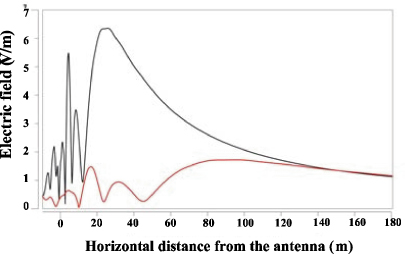
The base stations of mobile telephone networks emit very variable power values depending on the intensity of the communication traffic. Indeed, in high traffic periods, it is not rare for only one antenna to radiate an apparent power between 200 and 300 Watts. Laid out on masts or buildings, the antennas of these base stations (Figure 1.6) emit waves in a favored direction (primary lobe) to limit the electromagnetic disturbances. In practice, it appeared, during measurements, that radiations could be propagated by the means of secondary lobes and directly reach close dwellings like their occupants. Moreover, the presence of metallic reinforcements contained in concrete or in windows and doorframes, can modify the intensity, as well as the direction of the radiations, and make them not conform with the initial forecasts. The principal lobe from the antennas is generally tilted from 7° to the vertical, thus meeting the ground at distances ranging between 50 and 200 m from the foot of the mast. The aperture of the lobe, in a horizontal plane, is equal to 120° and the association of three antennas allows us to cover all the directions of space (Figure 1.7). As an example, Figure 1.7 presents the variations of the electric field emitted by a GSM antenna, according to the distance. The upper curve gives the variations measured in the principal direction of propagation, at 15 m from the ground, and the lower curve shows the variations at 1.5 m from the ground (OFEV, 2007).
Figure 1.6. Photograph of a typical relay-station (OFEV, 2007)

Figure 1.7. Variations of the electric field strength versus the distance from the antenna, in the more intense direction, and for two different heights from the ground: 15 m from the ground (upper curve) and 1.5 m from the ground (lower curve) (OFEV, 2007)
1.1.2.2.6. Radars
Radars are significant sources of radioelectric radiation in a close zone (distance less than 1 km) because of their power and the nature of the signal. The most disturbing radars are the air traffic control radars. They operate at frequencies ranging between 1,220 MHz and 1,370 MHz, with peak powers of about 1.5 MW. They emit impulses of a few microseconds duration and with a several hundred hertz repetition rate. The antenna usually turns at several revolutions per minute. The impulse of approach radars established in the Paris airport site (ADP) emit a peak power of 600 kW at a frequency of 2.8 GHz and have an antenna gain of about 30 dB.
Field strength measurements in a radius of 1 to 2 km around airport radars highlighted an electromagnetic field peak ranging from 3 to 120 V/m.
In certain cases, air traffic radars of the aerial navigation using a magnetron-like source of emission, radiate parasitic fields at very close frequencies from their fundamental frequency, but outside their allotted band. They can thus disturb other radioelectric services, including local radio-relay systems. Figure 1.8 shows the radioelectric spectrum of the emissions of Orly and Athis Mons radars, measured at the 58th floor of the Montparnasse Tower in Paris.
Figure 1.8. Field strength of the Orly and Athis Mons radars measured at the 58th floor of the Montparnasse Tower in Paris
1.1.2.2.7. Railway trains
In the railway electric field, related to the engine feeding systems, electromagnetic radiations comes from:
– harmonic currents at RFs from 9 kHz to 30 MHz, due to the overhead line. This line, conveying harmonic currents generated by the engine, behaves like an antenna and emits a parasitic magnetic field;
– electric arc created by the contact slipping pantograph-overhead line, at RFs ranging from 30 MHz to 1 GHz; according to the surface quality of materials in contact, their degree of wear and climatic conditions (moisture, ice, etc.), this slipping contact can be the seat of electric lightings (luminous arcs) and behaves like the localized source of a parasitic electric field.
This electromagnetic field, generated by a high-speed train, can be collected by a GSM antenna located near the pantograph of an engine (Alliot, 2007). Figure 1.9 shows an example recording of radiated fields, caused by several trains traveling at speeds ranging between 250 and 300 km/h. The recording was taken by a GSM antenna located on the roof at a distance of 5 m from the pantograph of the engine.
Figure 1.9. Typical wave form of an electric impulse emitted by a high-speed train and collected by a GSM Bi-band antenna (Alliot, 2007). a) Temporal wave form; b) frequency spectrum
1.1.2.3. Scientific and medical sources of electromagnetic fields
Scientific research uses a number of field-generating apparatuses: for example, material-heating devices, applying either the dielectric or induction effect; various subsystems of research and particle accelerators (cyclotrons, Van de Graaf, etc.) on plasmas; semiconductors, etc.
The medical sector also uses a number of field generating apparatuses: nuclear magnetic resonance (NMR), imagery by magnetic resonance (IMR), radiotherapy by microwaves.
1.1.3. Indoor and outdoor electric wires
Any electric conductor, and in particular electric cables or wire, in which a power is on, behaves like a real antenna. The only difference from a classic antenna is that a classic antenna is conceived to receive or emit an electromagnetic wave, whereas the electric cables or wire are not. Electromagnetic emission is only an induced phenomenon, able to disturb the localized sensitive apparatuses close to these electric cables or wires, which are outside or inside houses or buildings.
1.1.4. Fields resulting from all the emissions
With respect to the limit value for all the transmitting frequency bands, we must impose that the resulting field from all the RF emissions at a given place is limited and in accordance with the following formula:
![]()
1.2. Electromagnetic fields
Electromagnetic fields belong to our physical environment as well as the noise, heat, the light, etc. Referencing the electromagnetic spectrum, the frequencies can be seen to increase from several hertz to approximately 300 GHz.
Table 1.4 notes that the radio-electromagnetic fields are divided into five parts:
i) static fields and, more particularly the magnetostatic fields;
ii) fields at extremely low frequency (ELF) waves (0 to 10 kHz), including the frequency of the electric current sector (50 Hz);
iii) intermediate frequencies from 10 kHz to 10 MHz;
iv) RFs of 10 MHz with 300 MHz;
v) ultra high frequencies of 300 MHz with 300 GHz.
It is noted that energies of these radiations (E (eV) = 1.24/λ(μm)) remain very weak. For example, a wavelength of 1,000 meters corresponds to a very low energy of 1.24 neV (nanoelectron-Volt) and for a wavelength of 1 m, the quantum energy is only equal to 1.24 μeV.
Table 1.4. Fields and radioelectromagnetic non-ionizing radiation (NIR)
Tables 1.5 and 1.6 refer to radiations out of the field of this book; they are only given for comparison. Table 1.5 gives the optical radiations, such as infra-red, visible light and ultraviolet rays. Table 1.6 gives the ionizing radiations, for which the effects on living organisms can be devastating because of high quantum energy. Ionizing radiations can reach values much higher than 12.4 eV, whereas radioelectromagnetic radiations are almost equal to zero.
Table 1.5. Optics
Table 1.6. Ionizing radiations (IR)
Some characteristic frequencies and their associated wavelengths for specific emissions are noted as examples in Table 1.7.
Table 1.7. Some characteristic frequencies and associated wavelengths
| Frequency ν | Source of emission | Wavelength λ |
| 50 Hz | sector | 6,000 km |
| 1 MHz | transmitters, induction furnaces, etc. | 300 m |
| 27 MHz | transmitters, high frequency presses | 11.1 m |
| 900 MHz | mobile telephones | 0.33 m |
| 1,800 MHz | mobile telephones | 0.166 m |
| 2,450 MHz | Microwave ovens at high frequencies, WiFi, etc. | 12.2 cm |
| 10 GHz | radars | 3 cm |
It is commonly accepted that, for a dipole antenna, the known wave is formed at a distance greater than λ/2π. For smaller distances, we are in the near-field. The transition between the near-field and the far-field is progressive and it is only until 10 times λ/2π, that is to say 1.6λ, that we can really consider to be in the distant field. The zone ranging between λ/2π and 1.6λ is a transition zone between the two propagation modes. The wave will then be definitively formed at 480 m for 1 MHz, 18 m for 27 MHz and 52 cm for 900 MHz.
Consequently, any measurements at a short distance from the emission sources, which is often the case in professional exposures, are more difficult to make when the frequency decreases. For example, it is easier to characterize an exposure to 2, 450 MHz than to 27 MHz.
However, in the specific case of mobile telephones operating at 900 MHz or 1,800 MHz, in spite of low wavelength, the proximity of the head of the user is such that the far-field conditions are not reached (the ear-terminal distance is less than 5 cm). Consequently, it is necessary to take into account the impedance presented at the head to characterize the fields. This requires either calculation or modeling. Head-terminal interactions are not the focus of this chapter and interested readers may refer to the many existing articles on the subject, particularly recent articles, Chapter 9 of this book and Varsier et al. (2008).
1.3. Bibliography
Alliot J.-C., Sources de bruit, Compatibilité électromagnétique 1, Collection Technique et Scientifique des Télécommunications, Hermes — Lavoisier, pp 31 – 184, 2007.
Degeauque P. and Hamelin J., Electromagnetic Compatibility, Oxford University Press, 1993.
Degauque P. and Zeddam A., Compatibilité électromagnétique 1, des concepts aux applications, Collection Technique et Scientifique des Télécommunications, Hermes-Lavoisier, 2007a.
Degauque P. and Zeddam A., Compatibilité électromagnétique 2, des concepts aux applications, Collection Technique et Scientifique des Télécommunications, Hermes-Lavoisier, 2007b.
Labiod H., Wireless Ad Hoc and Sensor Network, ISTE — Wiley, 2008.
Moliton A., Electronique et photoélectronique des matériaux et composants 2, Hermes — Lavoisier, 2009.
OFEV Switzerland, www.umwelt-schweiz.ch, 2007.
Sizun H., Radio Wave Propagation for Telecommunication Applications, Springer, 2005.
Varsier N., Wake K., Taki M., Watanabe S., Takebayashi T., Yamaguchi N. and Kikuchi Y., “SAR characterization inside intracranial tumors for case-control epidemiologic studies on cellular phones and RF exposure”, Annals of Telecommunications, vol. 63, pp. 65–78, 2008.
Vautrin J.-P., “Mesurage de l'exposition humaine aux champs électromagnétiques”, Techniques de l'ingénieur, 2001.
1 Chapter written by Pierre-Noël FAVENNEC.