
24
3GPP LTE/LTE-Advanced Radio Access Technologies
Sassan Ahmadi
24.2 Overall Network Architecture
24.3 3GPP LTE Protocol Structure
24.4 Overview of the 3GPP LTE Physical Layer
Operating Frequencies and Bandwidths
Physical Random Access Channel
Multi-Antenna Schemes in 3GPP LTE/LTE-Advanced
24.5 Overview of the 3GPP LTE/LTE-Advanced Layer-2
Logical and Transport Channels
24.6 Radio Resource Control Functions
24.7 Mobility Management and Handover in 3GPP LTE/LTE-Advanced
24.1 Introduction
The growing demand for mobile Internet and wireless multimedia applications such as Internet browsing, interactive gaming, mobile TV, video and audio streaming has motivated development of broadband wireless access technologies in recent years. The 3rd-Generation Partnership Project (3GPP) initiated the work on the Long-Term Evolution (LTE) as part of 3GPP Release 8 in late 2004 [1]. The Evolved UMTS Terrestrial Radio Access Network (E-UTRAN) substantially improved user throughput, cell capacity, and reduced user-plane and control-plane latencies, bringing significantly improved user experience with full mobility. With the emergence of Internet protocol as the protocol of choice for carrying all types of traffic, the 3GPP LTE provides support for IP-based traffic with end-to-end Quality of Service (QoS). Voice traffic will be supported mainly as voice over IP, enabling better integration with other multimedia services. Initial deployments of 3GPP LTE began in late 2010 and commercial availability on a larger scale is expected in a few years. 3GPP LTE has been further enhanced in 3GPP Release 10 to satisfy the functional and service requirements of ITU-R/IMT-Advanced [2–5].
Unlike its predecessors, which were developed within the framework of Release 99 UMTS architecture, 3GPP specified the Evolved Packet Core (EPC) architecture to support the E-UTRAN through reduction in the number of network elements and simplification of functionality but most importantly allowing for connections and handover to other fixed and wireless access technologies, providing the network operators the ability to deliver seamless mobility. The main objectives of 3GPP LTE were to minimize the system and User Equipment (UE) complexities, to allow flexible deployments in the existing or new frequency bands, and to enable coexistence with other 3GPP and non-3GPP radio access technologies.
The downlink transmission scheme is based on conventional Orthogonal Frequency Division Multiple Access (OFDMA) to provide robustness against frequency selectivity of the communication channel and multipath effects while allowing for low-complexity receiver implementations at wider bandwidths. The uplink transmission scheme is based on DFT-spread OFDM. The use of DFT-spread OFDM transmission for the uplink was motivated by the lower Peak-to-Average Power Ratio (PAPR) of the transmitted signal compared to conventional OFDMA. This allows for more efficient usage of the power amplifier at the terminal, which translates into an increased coverage and/or reduced terminal power consumption.
The 3GPP LTE/LTE-Advanced supports both FDD and TDD duplex schemes as well as transmission bandwidths in the range of 1.4–100 MHz. The carrier aggregation; that is, the simultaneous transmission of multiple component carries to the same terminal, is used to support contiguous/noncontiguous bandwidths larger than 20 MHz. Component carriers do not have to be contiguous in frequency and can even be located in different frequency bands in order to utilize fragmented spectrum allocations by means of spectrum aggregation. Channel-dependent scheduling in time and frequency domains is supported for both downlink and uplink with the base station scheduler being responsible for dynamic selection of transmission format. Semi-persistent scheduling is supported to allow semi-static resource allocation to a given UE for a longer time period in order to reduce the control signaling overhead.
Multi-antenna transmission scheme is an integral part of 3GPP LTE/LTE-Advanced standards. The multi-antenna precoding with dynamic rank adaptation supports both spatial multiplexing (single-user MIMO) and beam-forming. Spatial multiplexing with up to eight layers in the downlink and four layers in uplink is supported. The multiuser MIMO scheme, where multiple users are assigned to the same time-frequency resources is also supported. The 3GPP LTE/LTE-Advanced further includes transmit diversity based on Space Frequency Block Coding (SFBC) or a combination of SFBC and Frequency Switched Transmit Diversity (FSTD).
Enhanced Inter-cell Interference Coordination (eICIC), where neighbor cells exchange information aiding the scheduling in order to reduce intercell interference, is also supported. The eICIC scheme can be used for homogenous deployments with nonoverlapping cells of similar transmission power, as well as for heterogeneous deployments where a higher-power cell overlays one or several lower-power nodes (e.g., femto-cells). The relay functionality is supported where the relay node appears as a conventional base station (e-Node B or eNB) to terminals but is wirelessly connected to the remaining part of the radio-access network using the 3GPP LTE/LTE-Advanced radio-interface.
This chapter describes the prominent functional features of 3GPP LTE/LTE-Advanced technologies including protocols, control signaling, transmission formats, and physical layer and MAC processing.
24.2 Overall Network Architecture
As shown in Figure 24.1, the evolved UMTS terrestrial radio access network consists of eNBs or equivalently E-UTRA base stations, providing the E-UTRA user-plane and control-plane protocol terminations toward the user equipment (mobile station). As part of the evolution from and enhancement of the legacy UMTS systems, the Radio Network Controller (RNC) functions have been included in the eNB to reduce the architectural complexity and further reduce the latency across the network. As illustrated in Figure 24.1, the eNBs are interconnected with each other through X2 interface [6]. The X2 interface allows eNBs to communicate directly with each other and coordinate their activities. The X2 interface is split into separate control and user planes. The X2 control plane carries X2 Application Protocol (X2AP) messages between eNBs and uses Stream Control Transmission Protocol (SCTP) for reliable delivery of messages. The X2AP is used to manage inter-eNB mobility and handovers, UE context transfers, intercell interference management and various error handling functions. The X2 user plane uses GPRS Tunneling Protocol (GTP-U) to tunnel user traffic between eNBs.

FIGURE 24.1 E-UTRAN architecture. (Adapted from 3GPP TS 36.300, Evolved Universal Terrestrial Radio Access (E-UTRA) and Evolved Universal Terrestrial Radio Access Network (E-UTRAN); Overall Description; Stage 2, December 2010.)
The eNBs are also connected via S1 interface to the EPC or more specifically to the Mobility Management Entity (MME) through the S1-MME reference point and to the Serving Gateway (S-GW) via the S1-U interface. The S1 interface supports a multi-point connection among MMEs/Serving Gateways and eNBs. The S1-MME carries S1 Application Protocol (S1AP) messages, using SCTP over IP to provide guaranteed data delivery. Each SCTP association between an eNB and an MME can support multiple UEs. The S1-MME is responsible for EPC bearer setup and release procedures, handover signaling, paging, and NAS signaling transport. The S1-U consists of GTP-U protocol running on top of User Datagram Protocol (UDP), which provides best-effort data delivery. One GTP tunnel is established for each radio bearer in order to carry user traffic between the eNB and the selected S-GW.
The E-UTRAN overall architecture is described in References 6 and 7. Some general principles taken into consideration in the design of E-UTRAN architecture as well as the E-UTRAN interfaces are as follows [6]:
Signaling and data transport networks are logically separated.
E-UTRAN and EPC functions are separated from transport functions. The addressing schemes used in E-UTRAN and EPC are not associated with the addressing schemes of transport functions. Some E-UTRAN or EPC functions reside in the same equipment.
The mobility for RRC connection is controlled by the E-UTRAN.
The interfaces are based on the logical model of the entity which is controlled through this interface.
One physical network element can implement multiple logical nodes.
The eNB typically performs the following functions [6]:
Radio Resource Management (RRM) including radio bearer control, radio admission control, connection management, dynamic allocation of resources to UEs in both uplink and downlink (i.e., scheduling).
Header compression and encryption of user payloads.
Selection of an MME at UE attachment when no routing to an MME can be determined from the information provided by the UE.
Routing of U-Plane data toward S-GW.
Scheduling and transmission of paging messages (originated from the MME).
Scheduling and transmission of broadcast information (originated from the MME).
Measurement and reporting for support of mobility and scheduling.
The MME is the key control-node for the 3GPP LTE access-network. It is responsible for idle mode UE tracking and paging procedure including retransmissions. The MME functions include Non-Access Stratum (NAS) signaling and NAS signaling security, Inter-core-network signaling for mobility between 3GPP access networks, Idle mode UE accessibility (including control and execution of paging retransmission), Tracking area list management (for UE in idle and active mode), Packet Data Network (PDN) gateway and S-GW selection, MME selection for handovers with MME change, Roaming, Authentication of the users, and Bearer management functions including dedicated bearer establishment [6,7]. The NAS signaling terminates at the MME and it is also responsible for generation and allocation of temporary identities to the UEs. It verifies the authorization of the UE to camp on the service provider's Public Land Mobile Network (PLMN) and enforces UE roaming restrictions.
The S-GW routes and forward user data packets, while also acting as the mobility anchor for the user-plane during inter-eNB handovers and as the anchor for mobility between 3GPP LTE and other 3GPP technologies. The S-GW functions include local mobility anchor point for inter-eNB handover, Mobility anchoring for inter-3GPP mobility, E-UTRAN idle mode downlink packet buffering and initiation of network triggered service request procedure, Lawful interception, Packet routing and forwarding, and Transport-level packet marking in the uplink and the downlink [6,7].
The Packet Data Network Gateway (P-GW) provides connectivity of the UE to external packet data networks by being the point of exit and entry of traffic for the UE. A UE may have simultaneous connectivity with more than one P-GW for accessing multiple packet data networks. The P-GW functions include Per-user packet filtering, Lawful interception, UE IP address allocation, and Transport level packet marking in the downlink [6,7].
24.3 3GPP LTE Protocol Structure
In this section, we describe the functions of different protocol layers and their location in the 3GPP LTE/LTE-Advanced protocol structure. Figure 24.2 shows the functional split between the eNB and EPC. In the control-plane, the NAS functional block is used for network attachment, authentication, setting up bearers, and mobility management. All NAS messages are ciphered and integrity protected by the MME and UE. The Radio Resource Control (RRC) sub-layer in the eNB makes handover decisions based on neighbor cell measurements reported by the UE, performs paging of the users over the air-interface, broadcasts system information, controls UE measurement and reporting functions such as the periodicity of Channel Quality Indicator (CQI) reports and further allocates cell-level temporary identifiers to active users. It also executes transfer of UE context from the serving eNB to the target eNB during handover, and performs integrity protection of RRC messages. The RRC sublayer is responsible for setting up and maintenance of radio bearers. Note that RRC sublayer in 3GPP protocol hierarchy is considered as Layer 3 [6,8].
In the user plane, the Packet Data Convergence Protocol (PDCP) sublayer is responsible for compressing or decompressing the headers of user-plane IP packets using Robust Header Compression (RoHC) to enable efficient use of air interface resources [6,9]. This layer also performs ciphering of both user-plane and control-plane traffic. Because the NAS messages are carried in RRC, they are effectively double ciphered and integrity protected, once at the MME and again at the eNB.
The Radio Link Control (RLC) sublayer is used to format and transport traffic between the UE and the eNB [6,18]. The RLC sublayer provides three different reliability modes for data transport; that is, Acknowledged Mode (AM), Unacknowledged Mode (UM), and Transparent Mode (TM). The unacknowledged mode is suitable for transport of real-time services since such services are delay sensitive and cannot tolerate delay due to retransmissions. The acknowledged mode is appropriate for nonreal-time services such as file transfers. The transparent mode is used when the size of packet data units are known in advance such as for broadcasting system configuration information. The RLC sublayer also provides sequential delivery of service data units to the upper layers and eliminates duplicate packets from being delivered to the upper layers. It may also segment the service data units. Furthermore, there are two levels of retransmissions for providing reliability, the Hybrid Automatic Repeat reQuest (HARQ) at the MAC sublayer and ARQ at the RLC sublayer. The ARQ is required to handle residual errors that are not corrected by HARQ. An N-process stop-and-wait HARQ protocol is employed that has asynchronous retransmissions in the downlink and synchronous retransmissions in the uplink. Synchronous HARQ means that the retransmissions of HARQ sub-packets occur at predefined periodic intervals. Hence, no explicit signaling is required to indicate to the receiver the retransmission schedule. Asynchronous HARQ offers the flexibility of scheduling retransmissions based on air interface conditions (i.e., scheduling gain).
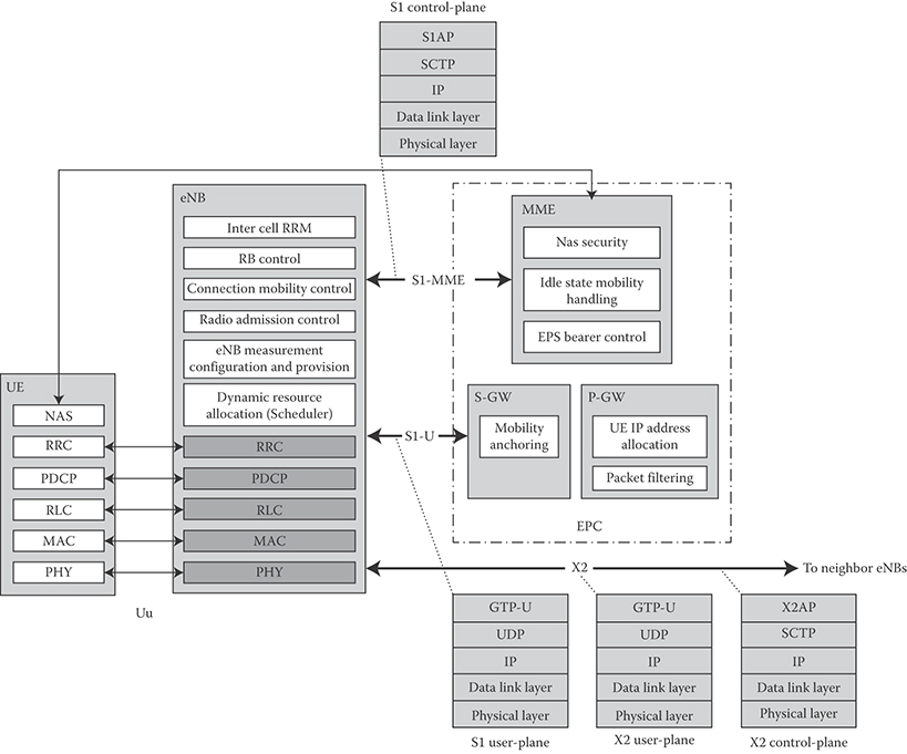
FIGURE 24.2 Protocol layers and function split in UE, eNB, MME, S-GW, and P-GW. (Adapted from 3GPP TS 36.300, Evolved Universal Terrestrial Radio Access (E-UTRA) and Evolved Universal Terrestrial Radio Access Network (E-UTRAN); Overall Description; Stage 2, December 2010.)
24.4 Overview of the 3GPP LTE Physical Layer
The main functional elements of the physical layer processing are described in the following sections [10–13].
24.4.1 Multiple Access Schemes
3GPP LTE/LTE-Advanced uses asymmetric multiple access schemes in the downlink and uplink. The multiple access scheme for the 3GPP LTE/LTE-Advanced physical layer is based on Orthogonal Frequency Division Multiple Access (OFDMA) with a Cyclic Prefix (CP) in the downlink and Single Carrier Frequency Division Multiple Access (SC-FDMA) with CP in the uplink.
The OFDMA scheme is particularly suited for frequency-selective channels and high data rates. It transforms a wideband frequency selective channel into a set of parallel flat fading narrowband channels. This ideally, allows the receiver to perform a less complex equalization process in frequency domain; that is, single-tap frequency-domain equalization.
24.4.1.1 Downlink Multiple Access
The downlink transmission scheme is based on conventional OFDMA using a cyclic prefix. The 10 ms radio frame is divided into 10 equally sized subframes. Each subframe is further divided into two slots of 0.5 ms length. The basic transmission parameters in the downlink are specified in Table 24.1.
The CP length is chosen to be longer than the maximum delay spread in the radio channel. For 3GPP LTE/LTE-Advanced, the normal CP length has been set to 4.69 µs, enabling the system to tolerate delay variations due to propagation over cells up to 1.4 km. Note that the insertion of longer CP increases the physical-layer overhead, thus reducing the overall throughput.
To provide enhanced multicast and broadcast services, 3GPP LTE/LTE-Advanced has the capability to transmit multicast and broadcast over a Single-Frequency Network (MBSFN), where a time-synchronized common waveform is transmitted from multiple eNBs, allowing macro-diversity combining of multicell transmissions at the UE. The cyclic prefix is utilized to mitigate the difference in the propagation delays, which makes the MBSFN transmission appear to the UE as a transmission from a single large cell. Transmission on a dedicated carrier for MBSFN with the possibility to use a longer CP with a subcarrier bandwidth of 7.5 kHz is supported as well as transmission of MBSFN on a carrier with both MBMS and unicast transmissions using time division multiplexing [6].
24.4.1.2 Uplink Multiple Access
The basic transmission scheme in the uplink is single-carrier transmission (SC-FDMA) with cyclic prefix to achieve uplink interuser orthogonality and to enable efficient frequency-domain equalization at the receiver side. The frequency-domain generation of the SC-FDMA signal, also known as DFT-spread OFDM, is similar to OFDMA and is illustrated in Figure 24.3. This allows for a relatively high degree of commonality with the downlink OFDMA baseband processing using the same parameters; for example, clock frequency, subcarrier spacing, FFT/IFFT size, and so on. The use of SC-FDMA in the uplink is mainly due to relatively inferior PAPR properties of OFDMA that results in worse uplink coverage compared to SC-FDMA. The PAPR characteristics are important for cost-effective design of UE power amplifiers.
TABLE 24.1 3GPP LTE/LTE-Advanced OFDMA Parameters
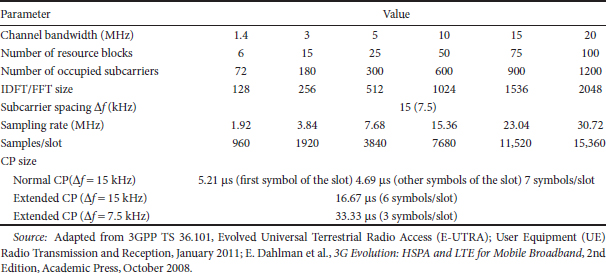
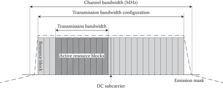
FIGURE 24.3 Transmitter/receiver structure of SC-FDMA. (Adapted from 3GPP TS 36.101, Evolved Universal Terrestrial Radio Access (E-UTRA); User Equipment (UE) Radio Transmission and Reception, January 2011.)
The subcarrier mapping in Figure 24.3 determines which part of the spectrum is used for transmission by inserting a suitable number of zeros at the upper and/or lower end. Between each DFT output sample L-1 zeros are inserted. A mapping with L = 1 corresponds to localized transmissions; that is, transmissions where the DFT outputs are mapped to consecutive subcarriers. There are two subcarrier mapping schemes (localized and distributed) that could be used in the uplink. However, 3GPP LTE only specified localized subcarrier mapping in the uplink.
24.4.2 Operating Frequencies and Bandwidths
The E-UTRA is designed to operate in the frequency bands defined in Table 24.2. The requirements were defined for 1.4, 3, 5, 10, 15, and 20 MHz bandwidth with a specific configuration in terms of number of resource blocks (see Table 24.2). Using carrier aggregation, a number of contiguous and/or noncontiguous frequency bands can be aggregated to create a virtually larger bandwidth.
Figure 24.4 illustrates the relationship between the total channel bandwidth and the transmission bandwidth; that is, the number of resource blocks. The 3GPP LTE/LTE-Advanced channel raster is 100 kHz, which means the center frequency must be a multiple of 100 kHz [14]. To support transmission in paired and unpaired spectrum, two duplexing schemes are supported: Frequency Division Duplex (FDD), allowing both full and half-duplex terminal operation, as well as Time Division Duplex (TDD). Table 24.2 shows the band classes where the 3GPP LTE systems can be deployed.
24.4.3 Frame Structure
Downlink and uplink transmissions are organized in form of radio frames with 10 ms duration. 3GPP LTE/LTE-Advanced supports two radio frame structures, Type 1, applicable to FDD duplex scheme and Type 2, applicable to TDD duplex scheme. In frame structure Type 1, as illustrated in Figure 24.5, each 10 ms radio frame is divided into 10 equally sized subframes. Each subframe consists of two equally sized slots. For FDD, 10 subframes are available for downlink transmission and 10 subframes are available for uplink transmissions in each radio frame. Uplink and downlink transmissions are separated in the frequency domain. The transmission time interval (TTI) of the downlink/uplink is 1 ms [10,6].
Frame structure Type 2 is illustrated in Figure 24.6. Each 10 ms radio frame consists of two 5 ms half-frames. Each half-frame consists of eight slots of 0.5 ms length and three special fields: Downlink Pilot Time Slot (DwPTS), Guard Period (GP), and Uplink Pilot Time Slot (UpPTS). The length of DwPTS and UpPTS is configurable subject to the total length of DwPTS, GP, and UpPTS being equal to 1 ms (see [10] for more details). Both 5 ms and 10 ms switching-point periodicity are supported. The first subframe in all configurations and the sixth subframe in configuration with 5 ms switching-point periodicity consist of DwPTS, GP, and UpPTS. The sixth subframe in configuration with 10 ms switching-point periodicity consists of DwPTS only. All other subframes consist of two equally sized slots.
TABLE 24.2 3GPP LTE/LTE-Advanced Band Classes

For TDD systems, the GP is reserved for downlink to uplink transition. Other subframes/fields are assigned for either downlink or uplink transmission as shown in Table 24.3. Uplink and downlink transmissions are separated in the time domain.
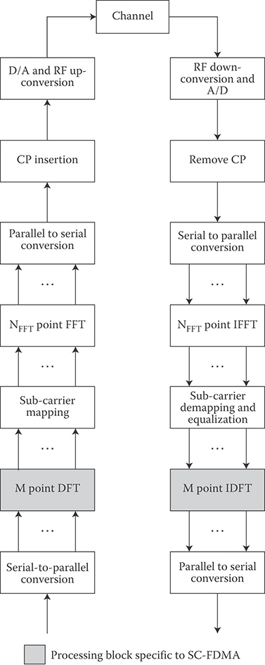
FIGURE 24.4 Illustration of the relationship between channel bandwidth and transmission bandwidth.
24.4.4 Physical Resource Blocks
The smallest time–frequency resource unit used for downlink/uplink transmission is called a resource element, defined as one subcarrier over one symbol [10]. For both TDD and FDD duplex schemes as well as in both downlink and uplink, a group of 12 subcarriers contiguous in frequency over one slot in time form a Resource Block (RB) as shown in Figure 24.7 (corresponding to one slot in the time domain and 180 kHz in the frequency domain). Transmissions are allocated in units of RB. One downlink/uplink slot using the normal CP length contains 7 symbols. There are 6, 15, 25, 50, 75, and 100 RBs corresponding to 1.4, 3, 5, 10, 15, 20 MHz channel bandwidths, respectively [10]. Note that the physical resource block size is the same for all bandwidths.

FIGURE 24.5 3GPP LTE/LTE-advanced FDD frame structure.
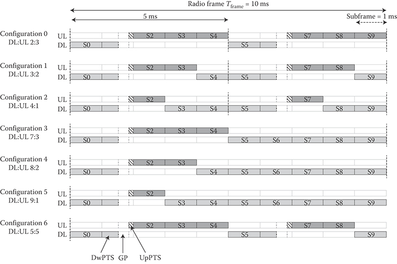
FIGURE 24.6 3GPP LTE/LTE-advanced TDD frame configurations.
TABLE 24.3 Uplink/Downlink Configurations in Frame Structure Type 2 where “S” denotes the Special Subframe

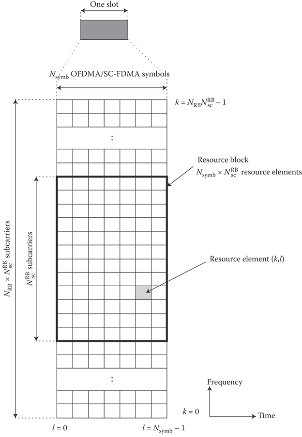
FIGURE 24.7 The structure of 3GPP LTE physical resource block. (Adapted from 3GPP TS 36.211, Evolved Universal Terrestrial Radio Access (E-UTRA); Physical Channels and Modulation, December 2010.)
24.4.5 Modulation and Coding
The baseband modulation schemes supported in the downlink and uplink of 3GPP LTE/LTE-Advanced are QPSK, 16QAM and 64QAM. The channel coding scheme for transport blocks in 3GPP LTE is Turbo Coding similar to UTRA, with the minimum coding rate of R = 1/3, two 8-state constituent encoders and a contention-free Quadratic Permutation Polynomial (QPP) turbo internal interleaver [11]. Trellis termination is performed by taking the tail bits from the shift register feedback after all information bits are encoded. The tail bits are padded after the encoding of information bits. Before the turbo coding, transport blocks are segmented into octet-aligned segments with a maximum information block size of 6144 bits. Error detection is supported by the use of 24 bit CRC. The coding and modulation schemes for various physical channels in the downlink and uplink of 3GPP LTE are shown in Table 24.4 [15,16].
24.4.6 Physical Channel Processing
Figure 24.7 illustrates different stages of 3GPP LTE physical channel processing in the downlink and uplink. In the downlink, the coded bits in each of the codewords are scrambled for transmission on a physical channel. The scrambled bits are modulated to generate complex-valued modulation symbols that are later mapped to one or several transmission layers. The complex-valued modulation symbols on each layer are precoded for transmission and are further mapped to resource elements for each antenna port. The complex-valued time-domain OFDMA signal for each antenna port is then generated following these stages [10].
In the uplink, the baseband signal is processed by scrambling the input coded bits and then by modulation of scrambled bits to generate complex-valued symbols. The complex-valued modulation symbols are transform-precoded (DFT-based precoding) and are later mapped to resource elements. The complex-valued time-domain SC-FDMA signal for each antenna port is then generated.
24.4.7 Reference Signals
In 3GPP LTE Release 8/9, four types of downlink reference signals are defined, cell-specific reference signals, associated with non-MBSFN transmission, MBSFN reference signals, associated with MBSFN transmission, positioning reference signals, and demodulation or UE-specific reference signals. There is one cell-specific reference signal transmitted per downlink antenna port [10]. Note that antenna port is a logical entity and shall not be confused with the physical transmit antennas, although there is a mapping between the two entities during operation in various transmission modes (see Figure 24.8). The cell-specific downlink reference signals consist of predetermined reference symbols that are inserted in the time-frequency grid over each subframe and are used for downlink channel estimation [10,6] and physical layer identifier (cell identifier) detection. The exact sequence is derived from cell identifiers. The number of downlink antenna ports with cell-specific reference signals equals 1, 2, or 4. The reference signal sequence is derived from a pseudo-random sequence and results in a QPSK type constellation. Cell-specific frequency shifts are applied when mapping the reference signal sequence to the sub-carriers. The two-dimensional reference signal sequence is generated as the symbol-by-symbol product of a two-dimensional orthogonal sequence and a two-dimensional pseudo-random sequence. There are 3 different two-dimensional orthogonal sequences and 168 different two-dimensional pseudo-random sequences. Each cell identity corresponds to a unique combination of one orthogonal sequence and one pseudo-random sequence, thus allowing for 504 unique cell identities (i.e., 168 cell identity groups with 3 cell identities in each group).
TABLE 24.4 Physical Channels and Signals and Their Corresponding Modulation Schemes for the 3GPP LTE Downlink and Uplink

The downlink MBSFN reference signals consist of known reference symbols inserted every other sub-carrier in the 3rd, 7th, and 11th OFDM symbols of subframe in case of 15 kHz subcarrier spacing and extended cyclic prefix. The MBSFN reference signals are transmitted on antenna port 4.
The UE-specific reference signals are supported for single-antenna-port transmission of PDSCH and transmitted on antenna port 5, 7, or 8. The UE-specific reference signals are also supported for spatial multiplexing on antenna ports 7 and 8. These reference signals are utilized for PDSCH coherent demodulation, if the PDSCH transmission is associated with the corresponding antenna port. They are transmitted only on the resource blocks to which the corresponding PDSCH is mapped. The UE-specific reference signals are not transmitted in resource elements where one of the physical channels or physical signals other than UE-specific reference signal are transmitted using resource elements with the same index pair regardless of their antenna port.
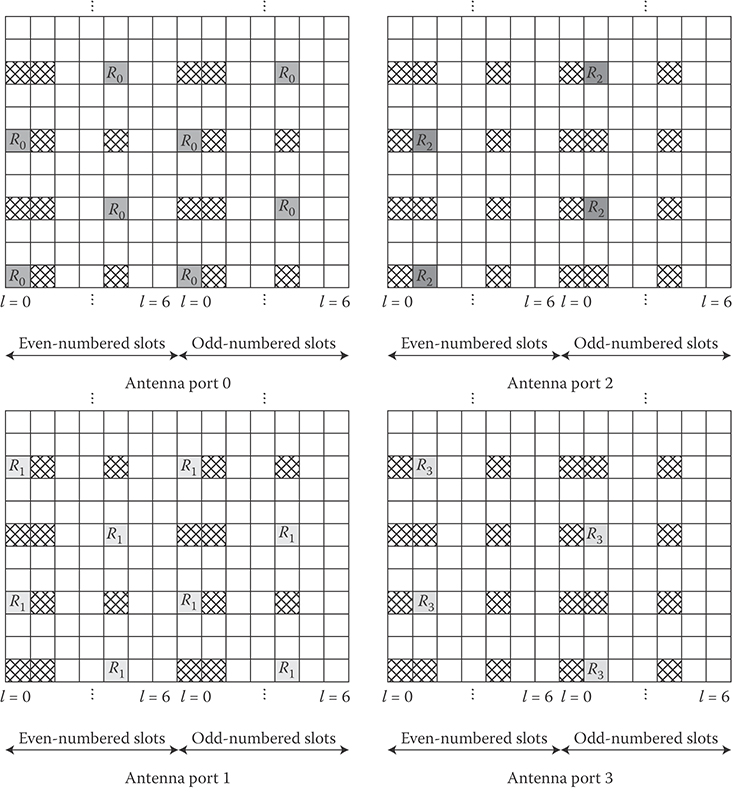
FIGURE 24.8 Downlink cell-specific reference signals for antenna ports 0, 1, 2, and 3. (Adapted from 3GPP TS 36.211, Evolved Universal Terrestrial Radio Access (E-UTRA); Physical Channels and Modulation, December 2010.)
Positioning reference signals are only transmitted in downlink subframes configured for positioning reference signal transmission. If both normal and MBSFN subframes are configured as positioning subframes within a cell, the OFDM symbols in an MBSFN subframe configured for positioning reference signal transmission use the same cyclic prefix as used for the first subframe. Otherwise, if only MBSFN subframes are configured as positioning subframes within a cell, the OFDM symbols configured for positioning reference signals in these subframes use the extended cyclic prefix. The positioning reference signals are transmitted on antenna port 6 and are not mapped to resource elements allocated to physical broadcast, primary and secondary synchronization channels, regardless of their antenna port.

FIGURE 24.9 Overview of downlink/uplink physical channel processing. (Adapted from 3GPP TS 36.211, Evolved Universal Terrestrial Radio Access (E-UTRA); Physical Channels and Modulation, December 2010.)
In 3GPP Release 10, a new set of reference signals called Channel State Information-Reference Signals (CSI-RS) were added which are used to support reporting of channel-state information from the user terminals to the network. The CSI reference signals are sparse in the time and frequency and transmitted at a configurable periodicity. Figure 24.9 shows the cell-specific reference signals corresponding to antenna ports 0 through 3 in the downlink. The physical resources at the locations of the reference signals of another antenna port are not used for data transmission on the other antenna ports.
The uplink reference signals, used for channel estimation for coherent demodulation, are transmitted in the 4th SC-FDMA symbol in each slot assuming normal CP. 3GPP LTE uses UE-specific reference signals in the uplink. The uplink reference signal sequence length equals the size (number of subcarriers) of the assigned resource. The uplink reference signals are based on Zadoff–Chu sequences that are either truncated or cyclically extended to the desired length. There are two types of uplink reference signals (1) the demodulation reference signal is used for channel estimation in the eNB receiver in order to demodulate control and data channels. It is located on the 4th symbol in each slot (for normal cyclic prefix) and spans the same bandwidth as the allocated uplink data, and (2) the sounding reference signal provides uplink channel quality information as a basis for scheduling decisions in the base station (see Figure 24.10). The UE sends a sounding reference signal in different parts of the bandwidths where no uplink data transmission is available. The sounding reference signal is transmitted in the last symbol of the subframe. The configuration of the sounding signal; for example, bandwidth, duration, and periodicity are configured by higher layers.
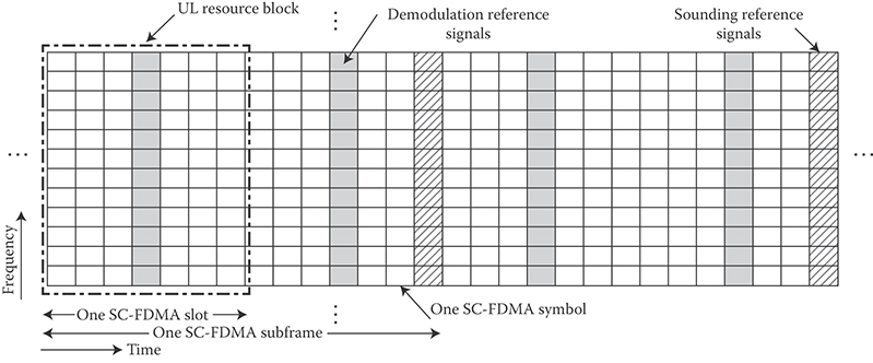
FIGURE 24.10 Uplink physical resource blocks and reference signals.
24.4.8 Physical Control Channels
The Physical Downlink Control Channel (PDCCH) is primarily used to carry scheduling information to individual UEs; that is, resource assignments for uplink and downlink data and control information. As shown in Figure 24.11, the PDCCH is located in the first few OFDM symbols of a subframe. For frame structure Type 2, PDCCH can also be mapped to the first two OFDM symbols of the DwPTS field. An additional Physical Control Format Indicator Channel (PCFICH), located on specific resource elements in the first OFDM symbol of the subframe, is used to indicate the number of OFDM symbols occupied by the PDCCH (1, 2, 3, or 4 OFDM symbols may be consumed where 4-OFDM-symbol PDCCH is only used when operating in the minimum supported system bandwidth). Depending on the number of users in a cell and the signaling formats conveyed on PDCCH, the size of PDCCH may vary. The information carried in PDCCH is referred to as Downlink Control Information (DCI), where depending on the purpose of the control message, different DCI formats are defined [15,16]. This information enables the UE to identify the location and size of the resources in that subframe, as well as provide the UE with information on the modulation and coding scheme, and HARQ operation. As mentioned earlier, the information fields in the downlink scheduling grant are used to convey the information needed to demodulate the downlink shared channel. They include resource allocation information such as resource block size and duration of assignment, transmission format such as multiantenna mode, modulation scheme, payload size, and HARQ operational parameters such as process number, redundancy version, and new data indicator. Similar information is also included in the uplink scheduling grants.

FIGURE 24.11 Structure of physical downlink control channel for frame structure Type 1. (Note that the density of the cell-specific reference signals is to not to scale in this figure.)

FIGURE 24.12 Structure of physical uplink control channel for frame structure type 1 and PUCCH format 1, 1a, and 1b.
Control channels are formed by aggregation of Control Channel Elements (CCE), each control channel element consists of a set of resource elements. Different code rates for the control channels are realized by aggregating different numbers of control channel elements. QPSK modulation is used for all control channels. There is an implicit relationship between the uplink resources used for dynamically scheduled data transmission, or the downlink control channel used for assignment, and the downlink ACK/NACK resource used for feedback.
The Physical Uplink Control Channel (PUCCH) is mapped to a control channel resource in the uplink as shown in Figure 24.12. A control channel resource is defined by a code and two resource blocks, consecutive in time, with hopping at the slot boundary. Depending on presence or absence of uplink timing synchronization, the uplink physical control signaling can differ. In the case of time synchronization being present, the out-of-band control signaling consists of CQI, ACK/NACK, and Scheduling Request (SR). Note that a UE only uses PUCCH when it does not have any data to transmit on PUSCH. If a UE has data to transmit on PUSCH, it would multiplex the control information with data on PUSCH.
By use of uplink frequency hopping on PUSCH, frequency diversity effects can be exploited and interference can be averaged. The UE derives the uplink resource allocation as well as frequency hopping information from the uplink scheduling grant. The downlink control information format 0 is used on PDCCH to convey the uplink scheduling grant. 3GPP LTE supports both intrasubframe and intersubframe frequency hopping. The hopping pattern is configured per cell by higher layers. In intrasubframe hopping, the UE hops to another frequency allocation from one slot to another within one subframe. In intersubframe hopping, the frequency resource allocation changes from one subframe to another.
The CQI reports are provided to the scheduler by the UE, measuring the current channel conditions. If MIMO transmission is used, the CQI includes necessary MIMO-related feedback.
The HARQ feedback in response to downlink data transmission consists of a single ACK/NACK bit per HARQ process. The PUCCH resources for SR and CQI reporting are assigned and can be revoked through RRC signaling. An SR is not necessarily assigned to UEs acquiring synchronization through the RACH (i.e., synchronized UEs may or may not have a dedicated SR channel). The PUCCH resources for SR and CQI are lost when the UE is no longer synchronized.
In 3GPP LTE, uplink control signaling includes ACK/NACK, CQI, scheduling request indicator, and MIMO feedback. When users have simultaneous uplink data and control transmission, control signaling is multiplexed with data prior to the DFT to preserve the single-carrier property in uplink transmission. In the absence of uplink data transmission, this control signaling is transmitted in a reserved frequency region on the band edge as shown in Figure 24.12. Note that additional control regions may be defined as needed. Allocation of control channels with their small occupied bandwidth to band edge resource blocks reduces out-of-band emissions caused by data resource allocations on innerband resource blocks and maximizes the frequency diversity for control channel allocations while preserving the single-carrier property of the uplink waveform.
24.4.9 Physical Random Access Channel
The physical layer random access preamble, illustrated in Figure 24.13 consists of a cyclic prefix of length TCP and a sequence part of length TSEQ. There are five random access preamble formats specified by the standard [10] where the parameter values depend on the frame structure and the random access configuration. The preamble format is configured through higher-layer signaling. Each random access preamble occupies a bandwidth corresponding to 6 consecutive resource blocks for both frame structures. The transmission of a random access preamble, if triggered by the MAC sublayer, is restricted to certain time and frequency resources. These resources are enumerated in increasing order of the subframe number within the radio frame and the physical resource blocks in the frequency domain such that index zero corresponds to the lowest numbered physical resource block and subframe within the radio frame.
The random access preambles are generated from Zadoff–Chu sequences with zero correlation zone. The network configures the set of preamble sequences the UE is allowed to use. There are 64 preambles available in each cell. The set of 64 preamble sequences in a cell is found by including first, in the order of increasing cyclic shift, all the available cyclic shifts of a root Zadoff–Chu sequence with the logical index RACH_ROOT_SEQUENCE, where RACH_ROOT_SEQUENCE is broadcasted as part of the System Information [10,15,16].
The random access procedure in 3GPP LTE consists of 4 steps. In step 1, the preamble is sent by UE. The time/frequency resource where the preamble is sent is associated with a Random Access Radio Network Temporary Identifier (RA-RNTI). In step 2, a random access response is generated by eNB and is sent on the downlink shared channel. It is addressed to the UE using the temporary identifier and contains a timing advance value, an uplink grant, and a temporary identifier. Note that eNB may generate multiple random access responses for different UEs which can be concatenated inside one MAC protocol data unit. The preamble identifier is contained in the MAC subheader of each random access response so that the UE can detect whether a random access response for the used preamble exists. In Step 3, UE will send an RRC CONNECTION REQUEST message on the uplink common control channel, based on the uplink grant received in the previous step. In Step 4, the eNB sends back a MAC PDU containing the uplink CCCH service data unit that was received in Step 3. The message is sent on downlink shared channel and addressed to the UE via the temporary identifier. When the received message matches the one sent in Step 3, the contention resolution is considered successful [13,15,16]; otherwise, the procedure is restarted at Step 1.
Paging is used for setting up network-initiated connection. A power-saving efficient paging procedure should allow the UE to sleep without having to process any information and only to briefly wake up at predefined intervals to monitor paging information (as part of control signaling in the beginning of each subframe) from the network [6,9].
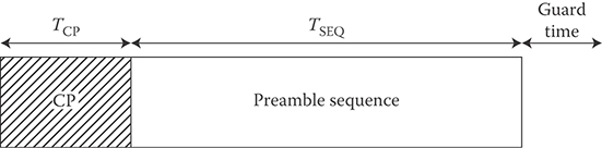
FIGURE 24.13 Random access preamble format.
24.4.10 Cell Selection
Cell search is a procedure performed by a UE to acquire timing and frequency synchronization with a cell and to detect the cell ID of that cell. 3GPP LTE uses a hierarchical cell search scheme similar to WCDMA. As shown in Figure 24.14, the E-UTRA cell search is based on successful acquisition of the following downlink signals: (1) the primary and secondary synchronization signals that are transmitted twice per radio frame, and (2) the downlink reference signals as well as based on the broadcast channel that carries system information such as system bandwidth, number of transmit antennas, and system frame number. The 504 available physical layer cell identities are grouped into 168 physical layer cell identity groups, each group containing 3 unique identities. The secondary synchronization signal carries the physical layer cell identity group, and the primary synchronization signal carries the physical layer identity 0, 1, or 2 [6].
As shown in Figure 24.11, the primary synchronization signal is transmitted on the 6th symbol of slots 0 and 10 of each Type 1 radio frame; it occupies 62 subcarriers, centered on the DC subcarrier. The primary synchronization signal is generated from a frequency-domain Zadoff–Chu sequence. The secondary synchronization signal is transmitted on the 5th symbol of slots 0 and 10 of each radio frame. It occupies 62 subcarriers centered on the DC sub-carrier. The second synchronization signal is an interleaved concatenation of two length-31 M-sequences. The concatenated sequence is scrambled with a scrambling sequence given by the primary synchronization signal [15,16].
As shown in Figure 24.11, PBCH is transmitted on OFDM symbols 0–3 of slot 1 and occupies 72 subcarriers centered on the DC subcarrier. The coded BCH transport block is mapped to 4 subframes within a 40 ms interval. The 40 ms timing is blindly detected; that is, there is no explicit signaling to indicate 40 ms timing [6,15,16]. These channels are contained within the central 1.08 MHz (corresponding to 6 resource blocks or 72 subcarriers) frequency band so that the system operation can be independent of the channel bandwidth.
24.4.11 Link Adaptation
Uplink link adaptation is used in order to improve data throughput in a fading channel. This technique varies the downlink modulation and coding scheme based on the channel conditions of each user. Different types of link adaptation are performed according to the channel conditions, the UE capability (such as the maximum transmission power, maximum transmission bandwidth, etc.), and the required QoS (such as the data rate, latency, and packet error rate, etc.). These link adaptation methods are as follows: (1) adaptive transmission bandwidth, (2) transmission power control, and (3) adaptive modulation and coding [6].
24.4.12 Multi-Antenna Schemes in 3GPP LTE/LTE-Advanced
For the 3GPP LTE Release 8/9 downlink, the 2 × 2 MIMO configuration is assumed to be the baseline; that is, two transmit antennas at the base station and two receive antennas at the terminal side [10,6,15,16]. Configurations with 4 transmit/receive antennas are also supported in the specification. Different downlink MIMO modes are supported in 3GPP LTE, which can be adapted based on channel condition, traffic requirements, and the UE capability. Those include Transmit diversity, Open-loop spatial multiplexing (no UE feedback), Closed-loop spatial multiplexing (with UE feedback), Multiuser MIMO (more than one UE is assigned to the same resource block), and Closed-loop rank-1 precoding.
In 3GPP LTE spatial multiplexing, up to two codewords can be mapped to different layers. Each codeword represents an output from the channel coder. The number of layers available for transmission is equal to the rank of the channel matrix. Precoding in transmitter side is used to support spatial multiplexing. This is achieved by multiplying the signal with a precoding matrix prior to transmission. The optimum precoding matrix is selected from a predefined codebook which is known to both eNB and UE. The optimum precoding matrix is the one which maximizes the capacity.

FIGURE 24.14 Cell selection procedure in 3GPP LTE.
The UE estimates the channel and selects the optimum precoding matrix. This feedback is provided to the eNB. Depending on the available bandwidth, this information is made available per resource block or group of resource blocks, since the optimum precoding matrix may vary between resource blocks. The network may configure a subset of the codebook that the UE is able to select from. In the case of UEs with high velocity, the quality of the feedback may deteriorate. Thus, an open-loop spatial multiplexing mode is also supported which is based on predefined settings for spatial multiplexing and precoding. In the case of 4 antenna ports, different precoders are cyclically assigned to the resource elements. The eNB will select the optimum MIMO mode and precoding configuration. The information is conveyed to the UE as part of the downlink control information on PDCCH.
In order for MIMO schemes to work properly, each UE has to report information about the channel to the base station. Several measurement and reporting schemes are available which are selected according to MIMO mode and network preference. The reporting may include wideband or narrowband CQI which is an indication of the downlink radio channel quality as experienced by this UE, Precoding Matrix Index (PMI) which is an indication of the optimum precoding matrix to be used in the base station for a given radio condition, and Rank Indication (RI) which is the number of useful transmission layers when spatial multiplexing is used [10,15,16].
In the case of transmit diversity mode, only one codeword can be transmitted. Each antenna transmits the same information stream, but with different coding. 3GPP LTE employs SFBC as transmit diversity scheme. A special precoding matrix is applied at the transmitter side in the precoding stage in Figure 24.9.
Cyclic Delay Diversity (CDD) is an additional type of diversity which can be used in conjunction with spatial multiplexing in 3GPP LTE. An antenna-specific delay is applied to the signals transmitted from each antenna port. This effectively introduces artificial multipath to the signal as seen by the receiver. As a special method of delay diversity, cyclic delay diversity applies a cyclic shift to the signals transmitted from each antenna port [10].
For the 3GPP LTE Release 8/9 uplink, MU-MIMO can be used. Multiple user terminals may transmit simultaneously on the same resource block. The scheme requires only one transmit antenna at UE side. The UEs sharing the same resource block have to apply mutually orthogonal pilot patterns. To take advantage of two or more transmit antennas, transmit antenna selection can be used. In this case, the UE has two transmit antennas but only one transmission chain. A switch will then choose the antenna that provides the best channel to the eNB [15,16].
3GPP LTE-Advanced extends the MIMO capabilities of 3GPP LTE Release 8/9 by supporting up to 8 downlink transmit-antennas and up to 4 uplink transmit-antennas. In addition to legacy MIMO transmission schemes, transmit diversity is possible in both downlink and uplink directions. In the downlink, using single-user spatial multiplexing scenario of 3GPP LTE-Advanced, up to two transport blocks can be transmitted to a scheduled UE in one subframe per downlink component carrier. Each transport block is assigned its own modulation and coding scheme. For HARQ ACK/NACK feedback on uplink, one bit is used for each transport block [10]. In addition to the spatial multiplexing scheme, the 3GPP LTE-Advanced downlink reference signal structure has been modified to allow an increased number of antennas and PDSCH demodulation as well as channel-state information estimation for the purpose of CQI/PMI/RI reporting when needed.
The reference signals for PDSCH demodulation are UE specific; that is, the PDSCH and the demodulation reference signals intended for a specific UE are subject to the same precoding operation. Therefore, these reference signals are mutually orthogonal between the layers at the eNB.
The design principle for the reference signals targeting PDSCH modulation is an extension of the concept of Release 8 UE-specific reference signals to multiple layers. Reference signals targeting CSI estimation are cell specific, are sparse in the frequency and time domain and are punctured into the data region of normal subframes.
With 3GPP LTE-Advanced, a scheduled UE may transmit up to two transport blocks. Each transport block has its own modulation and coding scheme. Depending on the number of transmission layers, the modulation symbols associated with each of the transport blocks are mapped to one or two layers. The transmission rank can be dynamically adapted. Different codebooks are defined depending on the number of layers that are used. Furthermore, different precoding is used depending on whether 2 or 4 transmit antennas are available. Also the number of bits used for the codebook index is different depending on the 2 and 4 transmit antenna case, respectively.
For uplink spatial multiplexing with two transmit-antennas, a 3-bit precoding method is defined. In contrast to the Release 8 downlink scheme, where several matrices for full-rank transmission are available, only the identity precoding matrix is supported in 3GPP LTE-Advanced uplink direction. 3GPP LTE-Advanced further supports transmit diversity in the uplink. However, for those UEs with multiple transmit antennas, an uplink single-antenna-port mode is defined. In this mode, the Release 10 UE behavior is the same as the one with a single antenna from eNB's point of view and it is always used before the eNB is aware of the UE antenna configuration. In the transmit diversity scheme, the same modulation symbol from the uplink channel is transmitted from two antenna ports, on two separate orthogonal resources.
24.5 Overview of the 3GPP LTE/LTE-Advanced Layer-2
The Layer-2 functions in 3GPP LTE/LTE-Advanced are classified into MAC, RLC, and PDCP sublayers [6,17,18,9,8]. Figures 24.15 and 24.16 illustrate the structure of Layer-2 in 3GPP LTE/LTE-Advanced downlink and uplink. The Service Access Point (SAP) for peer-to-peer communication is marked with circles at the interface between the sublayers. The SAP between the physical layer and the MAC sublayer provides the transport channels. The SAP between the MAC sublayer and the RLC sublayer provides the logical channels. The multiplexing of several logical channels (i.e., radio bearers) on the same transport channel (i.e., transport block) is performed by the MAC sublayer [6].
In the case of carrier aggregation, the multicarrier nature of the physical layer is only exposed to the MAC sublayer for which one HARQ entity is required per serving cell. In both uplink and downlink, there is one independent HARQ entity per serving cell and one transport block is generated per TTI per serving cell in the absence of spatial multiplexing. Each transport block and the associated HARQ retransmissions are mapped to a single serving cell.

FIGURE 24.15 3GPP LTE/LTE-advanced layer-2 structure in the downlink. (Adapted from 3GPP TS 36.300, Evolved Universal Terrestrial Radio Access (E-UTRA) and Evolved Universal Terrestrial Radio Access Network (E-UTRAN); Overall Description; Stage 2, December 2010.)

FIGURE 24.16 3GPP LTE/LTE-advanced layer-2 structure in the uplink. (Adapted from 3GPP TS 36.300, Evolved Universal Terrestrial Radio Access (E-UTRA) and Evolved Universal Terrestrial Radio Access Network (E-UTRAN); Overall Description; Stage 2, December 2010.)
The services and functions provided by the MAC sublayer can be summarized as follows:
Mapping between logical channels and transport channels;
Multiplexing/de-multiplexing of RLC protocol data units corresponding to one or different radio bearers into/from transport blocks delivered to/from the physical layer on transport channels;
Traffic volume measurement reporting;
Error correction through HARQ;
Priority handling between logical channels of one UE;
Priority handling between UEs through dynamic scheduling;
Transport format selection;
24.5.1 Logical and Transport Channels
The logical and transport channels in 3GPP LTE/LTE-Advanced are illustrated in Figures 24.17 and 24.18, respectively. Each logical channel type is defined by what type of information is transferred. The logical channels are generally classified into two groups: (1) Control Channels (for the transfer of control-plane information) and (2) Traffic Channels (for the transfer of user-plane information) as shown in Figure 24.17 [6].

FIGURE 24.17 Classification of 3GPP LTE logical channels. (Adapted from 3GPP TS 36.300, Evolved Universal Terrestrial Radio Access (E-UTRA) and Evolved Universal Terrestrial Radio Access Network (E-UTRAN); Overall Description; Stage 2, December 2010.)
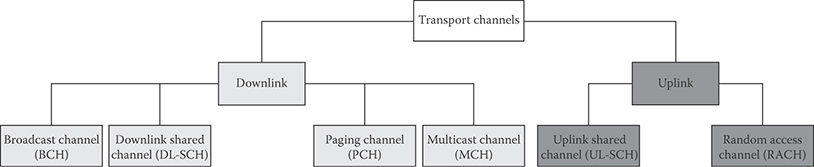
FIGURE 24.18 Classification of 3GPP LTE transport channels. (Adapted from 3GPP TS 36.300, Evolved Universal Terrestrial Radio Access (E-UTRA) and Evolved Universal Terrestrial Radio Access Network (E-UTRAN); Overall Description; Stage 2, December 2010.)
The control channels are exclusively used for transfer of control-plane information. The control channels supported by MAC can be classified as follows (see Figure 24.17):
Broadcast Control Channel (BCCH): A downlink channel for broadcasting system control information.
Paging Control Channel (PCCH): A downlink channel that transfers paging information and system information change notifications. This channel is used for paging when the network does not know the location of the UE.
Common Control Channel (CCCH): Channel for transmitting control information between UEs and eNBs. This channel is used for UEs having no RRC connection with the network.
Multicast Control Channel (MCCH): A point-to-multipoint downlink channel used for transmitting MBMS control information from the network to the UE, for one or several MTCHs. This channel is only used by UEs that receive MBMS.
Dedicated Control Channel (DCCH): A point-to-point bidirectional channel that transmits dedicated control information between a UE and the network. It is used by UEs that have an RRC connection.
The traffic channels are exclusively used for the transfer of user-plane information. The traffic channels supported by MAC can be classified as follows (as shown in Figure 24.18):
Dedicated Traffic Channel (DTCH): A point-to-point bidirectional channel dedicated to a single UE for the transfer of user information.
Multicast Traffic Channel (MTCH): A point-to-multipoint downlink channel for transmitting traffic data from the network to the UE. This channel is only used by UEs that receive MBMS.
The physical layer provides information transfer services to MAC and higher layers. The physical layer transport services are described by how and with what characteristics data are transferred over the radio interface. This should be clearly separated from the classification of what is transported, which relates to the concept of logical channels at MAC sublayer. As shown in Figure 24.18, downlink transport channels can be classified as follows:
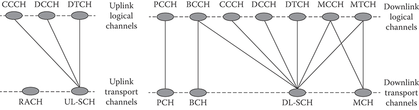
FIGURE 24.19 Mapping of logical to transport channels in the downlink and uplink. (Adapted from 3GPP TS 36.300, Evolved Universal Terrestrial Radio Access (E-UTRA) and Evolved Universal Terrestrial Radio Access Network (E-UTRAN); Overall Description; Stage 2, December 2010.)
Broadcast Channel (BCH) that is characterized by fixed, predefined transport format and is required to be broadcasted in the entire coverage area of the cell.
Downlink Shared Channel (DL-SCH) that is characterized by support for HARQ, support for dynamic link adaptation by varying the modulation, coding and transmit power, possibility for broadcast in the entire cell, possibility to use beamforming, support for both dynamic and semi-static resource allocation, support for UE discontinuous reception to enable power saving, and support for MBMS transmission.
Paging Channel (PCH) that is characterized by support for UE discontinuous reception in order to enable power saving, requirement for broadcast in the entire coverage area of the cell, mapped to physical resources which can be used dynamically also for traffic or other control channels.
Multicast Channel (MCH) which is characterized by requirement to be broadcast in the entire coverage area of the cell, support for macro-diversity combining of MBMS transmission on multiple cells, support for semi-static resource allocation.
The uplink transport channels are classified as follows (see Figure 24.18):
Uplink Shared Channel (UL-SCH) which is characterized by possibility to use beamforming, support for dynamic link adaptation by varying the transmit power and modulation and coding schemes, support for HARQ, support for both dynamic and semi-static resource allocation.
Random Access Channel (RACH) that is characterized by limited control information and collision risk.
The mapping of the logical channels to the transport channels in the downlink and uplink is shown in Figure 24.19.
As shown in Figures 24.15 and 24.16, the main services and functions provided by the RLC sublayer include Transfer of upper layer PDUs supporting AM or UM, TM data transfer, Error correction through ARQ (since CRC check is provided by the physical layer, no CRC is needed at RLC level), Segmentation according to the size of the transport block, Re-segmentation of PDUs that need to be retransmitted, Concatenation of SDUs for the same radio bearer, In-sequence delivery of upper layer PDUs except during handover, Duplicate detection, and Protocol error detection and recovery.
24.5.1.1 ARQ and HARQ in 3GPP LTE/LTE-Advanced
The E-UTRA provides ARQ and HARQ functionalities. The ARQ functionality provides error correction by retransmissions in acknowledged mode at Layer-2. The HARQ functionality ensures delivery between peer entities at Layer-1. The HARQ within the MAC sublayer is characterized by an N-process stop-and-wait protocol and retransmission of transport blocks upon failure of earlier transmissions. The ACK/NACK transmission in the FDD mode refers to the downlink packet that was received 4 subframes earlier. In TDD mode, the uplink ACK/NACK timing depends on the uplink/downlink configuration. For TDD, the use of a single ACK/NACK response for multiple PDSCH transmissions is possible. A total of 8 HARQ processes are supported [6,15,16].
An asynchronous adaptive HARQ is used in the downlink. The uplink ACK/NACK signaling in response to downlink retransmissions is sent on PUCCH or PUSCH. The PDCCH signals the HARQ process number and whether it is a fresh transmission or retransmission. The retransmissions are always scheduled through PDCCH.
A synchronous HARQ scheme is supported in the uplink. The maximum number of retransmissions can be configured per UE basis as opposed to per radio bearer. The downlink ACK/NACK signaling in response to uplink retransmissions is sent on PHICH.
The ARQ functionality within the RLC sub-layer is responsible for retransmission of RLC PDUs or RLC PDU segments. The ARQ retransmissions are based on RLC status reports and optionally based on HARQ/ARQ interactions. The polling for RLC status report is used when needed by RLC and status reports can be triggered by upper layers [6].
24.5.1.2 Packet Data Convergence Sublayer
Services and functions provided by the PDCP sublayer for the user plane include header compression and decompression, transfer of user data between NAS and RLC sublayer, sequential delivery of upper-layer PDUs at handover for RLC AM, duplicate detection of lower layer SDUs at handover for RLC AM, retransmission of PDCP SDUs at handover for RLC AM, and ciphering.
Services and functions provided by the PDCP for the control-plane include ciphering and integrity protection and transfer of control-plane data where PDCP receives PDCP SDUs from RRC and forward it to the RLC sublayer and vice versa.
24.6 Radio Resource Control Functions
The main services and functions of the RRC sublayer include [6]
Broadcast of system information
Paging
Establishment, maintenance, and release of a RRC connection between the UE and E-UTRAN including allocation of temporary identifiers between UE and E-UTRAN and configuration of signaling radio bearer(s) for RRC connection
Security functions including key management
Establishment, configuration, maintenance, and release of point-to-point radio bearers
Mobility functions including UE measurement reporting and control of the reporting for intercell and inter-RAT mobility, handover, UE cell selection and reselection and control of cell selection and reselection, context transfer at handover.
Establishment, configuration, maintenance, and release of radio bearers for MBMS services
QoS management functions
UE measurement reporting and control of the reporting
The RRC consists of the following states:
RRC_IDLE is a state where a UE-specific Discontinuous Reception (DRX) may be configured by upper layers. In the idle mode, the UE is saving power and does not inform the network of each cell change. The network knows the location of the UE to the granularity of a few cells, called the Tracking Area (TA). The UE monitors a paging channel to detect incoming traffic, performs neighboring cell measurements and cell selection/reselection, and acquires system information.
TABLE 24.5 Summary of the Differences between MAC and RRC Control

RRC_CONNECTED is a state where transfer of unicast data to/from UE is performed and the UE may be configured with a UE specific DRX or Discontinuous Transmission (DTX). The UE monitors control channels associated with the shared data channel to determine if data is scheduled for it, sends channel quality and feedback information, performs neighboring cell measurements and measurement reporting, and acquires system information.
The main difference between MAC and RRC control lies in the signaling reliability. The signaling corresponding to state transitions and radio bearer configurations should be performed by the RRC sublayer due to signaling reliability. The different characteristics of MAC and RRC control are summarized in Table 24.5.
24.7 Mobility Management and Handover in 3GPP LTE/LTE-Advanced
In order to support mobility, a 3GPP LTE-compliant UE may conduct the following measurements (physical layer measurements include Reference Signal Received Power and E-UTRA carrier Received Signal Strength Indicator [6]):
Intrafrequency E-UTRAN measurements
Interfrequency E-UTRAN measurements
Inter-RAT measurements
Measurement commands are used by E-UTRAN to instruct the UE to start measurements, modify measurements or stop measurements. The reporting criteria that are used include event-triggered reporting, periodic reporting, and event-triggered periodic reporting.
In RRC_CONNECTED state, network-controlled UE-assisted handovers are performed and various DRX cycles are supported. In RRC_IDLE state, cell reselections are performed and DRX is supported.
The Intra-E-UTRAN-Access mobility support for UEs in Evolved Packet System (EPS) Connection Management (ECM-CONNECTED) manages all necessary steps for relocation or handover procedures, such as processes that precede the final handover decision on the serving network, preparation of resources on the target network, commanding the UE to the new radio resources, and finally releasing resources on the serving network side. It contains mechanisms to transfer context data between eNBs and to update node relations on control plane and user plane. The UE makes measurements of attributes of the serving and neighbor cells to enable the process [6]. Depending on whether the UE needs transmission/reception gaps to perform the relevant measurements, measurements are classified as gap assisted or nongap assisted. A nongap-assisted measurement is a measurement on a cell that does not require transmission/reception gaps to allow the measurement to be performed. A gap-assisted measurement is a measurement on a cell that does require transmission/reception gaps to allow the measurement to be performed. Gap patterns are configured and activated by the RRC functional block [6].
The handover procedure is performed without EPC involvement; that is, preparation messages are directly exchanged between the eNBs. The release of the resources at the serving eNB (or source eNB) during the handover completion phase is triggered by the eNB. Figure 24.20 illustrates the handover procedure between eNBs within the same MME/S-GW. After the downlink path is switched at the S-GW, downlink packets on the forwarding path and on the new direct path may arrive interchanged at the target eNB (see Figure 24.20). The target eNB should first deliver all forwarded packets to the UE before delivering any of the packets received on the new direct path. Upon handover, the serving eNB forward in an orderly manner all downlink PDCP SDUs that have not been acknowledged by the UE to the target eNB. The serving eNB discards any remaining downlink RLC PDUs. Correspondingly, the source eNB does not forward the downlink RLC context to the target eNB.
The measurements to be performed by a UE for intra/interfrequency mobility can be controlled by E-UTRAN, using broadcast or dedicated control signaling. In RRC_IDLE state, a UE follows the measurement parameters defined for cell reselection. In RRC_CONNECTED state, a UE follows the measurement configurations specified by RRC managed by the E-UTRAN. The neighbor cell measurements performed by the UE are intrafrequency measurements when the current and target cell operate on the same carrier frequency. The neighbor cell measurements performed by the UE are interfrequency measurements when the neighbor cell operates on a different carrier frequency compared to the current cell.

FIGURE 24.20 Intra-MME/S-GW handover procedures. (Adapted from 3GPP TS 36.300, Evolved Universal Terrestrial Radio Access (E-UTRA) and Evolved Universal Terrestrial Radio Access Network (E-UTRAN); Overall Description; Stage 2, December 2010.)
24.8 Multicarrier Operation
When carrier aggregation is configured, the UE only has one RRC connection with the network. At RRC connection establishment/reestablishment/handover, one serving cell provides the NAS mobility information, and at RRC connection re-establishment/handover, one serving cell provides the security input. This cell is referred to as the Primary Cell (PCell). In the downlink, the carrier corresponding to the PCell is the downlink primary component carrier, while in the uplink it is the uplink primary component carrier. Depending on UE capabilities, Secondary Cells (SCells) can be configured to form, together with the PCell, a set of serving cells. In the downlink, the carrier corresponding to a SCell is a downlink secondary component carrier, while in the uplink it is an uplink secondary component carrier. The configured set of serving cells for a UE always consist of one PCell and one or more SCells. For each SCell the usage of uplink resources by the UE in addition to the downlink ones is configurable. From the UE point of view, each uplink resource only belongs to one serving cell. The number of serving cells that can be configured depends on the aggregation capability of the UE. The PCell can only be changed with handover procedure (i.e., with security key change and RACH procedure). The PCell is used for transmission of PUCCH and unlike SCells, PCell cannot be deactivated. The reestablishment is triggered only when PCell experiences a radio link failure and not when SCells experience radio link failure. The NAS information is obtained from PCell. The reconfiguration, addition, and removal of SCells can be performed by RRC signaling. In intra-LTE handover, RRC can also add, remove, or reconfigure SCells for usage with the target PCell. When adding a new SCell, dedicated RRC signaling is used for sending all required system information of the SCell; that is, while in connected mode, UEs do not need to acquire broadcasted system information directly from the SCells.
References
1. 3GPP TS 25.913, Requirements for Evolved UTRA (E-UTRA) and Evolved UTRAN (E-UTRAN), March 2006.
2. 3GPP TR 36.913, Requirements for Further Advancements for E-UTRA (LTE-Advanced), June 2008.
3. 3GPP TR 36.814, Further Advancements for E-UTRA Physical Layer Aspects, March 2010.
4. 3GPP TR 36.912, Further Advancements for E-UTRA (LTE-Advanced), June 2010.
5. ITU Global Standard for International Mobile Telecommunications ‘IMT-Advanced’, http://www.itu.int/ITU-R.
6. 3GPP TS 36.300, Evolved Universal Terrestrial Radio Access (E-UTRA) and Evolved Universal Terrestrial Radio Access Network (E-UTRAN); Overall Description; Stage 2, December 2010.
7. 3GPP TS 36.401, Evolved Universal Terrestrial Radio Access Network (E-UTRAN); Architecture Description, December 2010.
8. 3GPP TS 36.331, Evolved Universal Terrestrial Radio Access (E-UTRA); Radio Resource Control (RRC); Protocol Specification, December 2010.
9. 3GPP TS 36.323, Evolved Universal Terrestrial Radio Access (E-UTRA); Packet Data Convergence Protocol (PDCP) Specification, December 2010.
10. 3GPP TS 36.201, Evolved Universal Terrestrial Radio Access (E-UTRA); Long Term Evolution (LTE) Physical Layer; General description, December 2010.
11. 3GPP TS 36.211, Evolved Universal Terrestrial Radio Access (E-UTRA); Physical Channels and Modulation, December 2010.
12. 3GPP TS 36.212, Evolved Universal Terrestrial Radio Access (E-UTRA); Multiplexing and Channel Coding, December 2010.
13. 3GPP TS 36.213, Evolved Universal Terrestrial Radio Access (E-UTRA); Physical layer Procedures, December 2010.
14. 3GPP TS 36.101, Evolved Universal Terrestrial Radio Access (E-UTRA); User Equipment (UE) Radio Transmission and Reception, January 2011.
15. E. Dahlman , 3G Evolution: HSPA and LTE for Mobile Broadband, 2nd Edition, Academic Press, UK, October 2008.
16. Stefania Sesia, Issam Toufik, Matthew Baker, LTE, the UMTS Long Term Evolution: From Theory to Practice, John Wiley & Sons, UK, April 2009.
17. 3GPP TS 36.321, Evolved Universal Terrestrial Radio Access (E-UTRA); Medium Access Control (MAC) Protocol Specification, December 2010.
18. 3GPP TS 36.322, Evolved Universal Terrestrial Radio Access (E-UTRA); Radio Link Control (RLC) Protocol Specification, December 2010.