
35
Wireless Mesh Networks
Hyunok Lee
35.2 MAC Framework and Protocols
Control Time Slot Assignment Protocol
Data Time Slot Access Control Protocol
Performance under Two Different ACC Schemes
Performance under Different Mesh Sizes
35.1 Introduction
Multihop wireless communication networks have been of increasing interest over the last decade. Two main types of such networks have emerged: mobile ad-hoc networks (MANETs) and wireless mesh networks (WMNs). MANETs are infrastructure-less, nonhierarchical wireless networks where all network entities can move and function as routers and discover and maintain routes to other entities in the network. On the other hand, WMNs typically have a hierarchical structure and are supported by an infrastructure. Furthermore, the functionalities of the network entities may vary significantly across the layers of the hierarchical network structure. While MANETs have been historically envisioned to serve very specialized applications, such as battlefields and emergency situations, WMNs have inspired numerous general applications ranging from broadband home networking to community networks to high-speed metropolitan area networks (MANs) [1–3]. Particularly, large-scale WMNs with infrastructure support have been considered as an affordable and scalable solution to provide broadband packet data communications across wide geographic areas, thanks to their inherent advantages such as robustness to node failures, ease of deployment and maintenance, and low initial deployment cost [1–3].
In this chapter, we consider large-scale WMNs that serve as wireless access networks over large geographic areas. Such an application scenario of WMNs has often been proposed to have a layered network structure [4,5], which typically contains end-users (EUs) at the lowest layer, wireless mesh routers (MRs) in the middle layer, and other aggregation nodes at the top layer. The aggregation nodes of the highest layer may include another set of wireless entities that communicate wirelessly with the wireless MRs of the middle layer, or may be entirely wired through, for example, optical or DSL networks. In this chapter, we focus on the two lowest layers that consist of EUs and wireless MRs. A set of wireless MRs is assumed to be colocated with wired network entities called gateway routers (GRs).
Substantial research on WMNs has been conducted and several protocols have been proposed by various standardization bodies [3]. Particularly, routing for multihop wireless communication networks has been extensively studied in the context of MANETs [6–9] and more recently for WMNs [10–12]. Compared to routing, research on medium access control (MAC) for WMNs has been relatively sparse. The majority of the studies on MAC for WMNs consider contention-based schemes such as the IEEE 802.11 MAC protocol that is based on the carrier sense multiple access (CSMA) with collision avoidance (CA) principle. CSMA/CA-based schemes initiate the assessment of the availability of the medium or resources for transferring data packets mainly by sensing or measuring the power level of the medium directly. On the other hand, another type of MAC schemes [13–15] has been proposed. These schemes allocate separate resources for control and data packets, and the availability of resources for transferring data packets is assessed through exchanging control packets using control resources. Data resources are then reserved through these control packets.
The former type of MAC schemes based on the CSMA/CA principle inherently has less control overhead compared to the latter type of MAC schemes and thus may lead to higher network throughput when the traffic load is light. However, as the traffic load increases and more nodes need to acquire the medium simultaneously, it may become possible to coordinate data packet transmissions among nodes more efficiently when resources are divided for control and data packets and the availability or usage of data resources can be known and controlled by exchanging control packets. In this chapter, we focus on the latter type of MAC schemes.
In this chapter, we present the performance of large-scale WMNs that serve as access networks over large geographic areas. The WMNs employ a set of MAC protocols created in [16–18] that belongs to the latter type of MAC schemes described above, and their performance is evaluated through a large simulator developed in [16–19] that includes measurements-based models for radio propagation and interference calculation for a large built-in urban area. The simulator also captures the stochastic network behavior resulting from random traffic arrivals, admission control, and queuing. Through extensive simulations incorporating such details, we determine the performance of the WMNs. Primary factors are identified across the physical (PHY), MAC, and routing layers of network functions that affect the performance and their intricate interactions are examined to explain the behavior of fundamental performance metrics including the network throughput, per-session throughput, and blocking and dropping rates.
35.2 MAC Framework and Protocols
35.2.1 MAC Framework
We consider a MAC framework that supports explicit cooperation among MRs for resource reservation for data transmission. We consider a time division multiple access (TDMA) and time division duplex (TDD)-based framework with a single-frequency channel. MRs and EUs share the same frequency channel. Time is divided into time slots and there are two types of time slots: one for control and the other for data. In our TDMA, an MR uses different data time slots for serving different EUs. However, each data time slot is reused across the network. In TDD, an MR or an EU cannot transmit and receive simultaneously.
Within this framework, the overall operation of the network is as follows. When the network is deployed, it enters the preoperation phase during which the network runs a control time slot assignment protocol. Once control time slots are assigned to MRs, the network starts to run a routing protocol to construct routing tables at MRs. Once the network is set up, it enters the normal operation phase during which it executes a data time slot access control protocol to serve EUs. The network needs to rerun the control time slot assignment protocol if a new MR is added to the network. In addition, routing tables need to be reconstructed if an MR fails or a new MR is added to the network. The network could perform such reconfiguration of control time slots or routing tables proactively by entering the preoperation phase periodically.
35.2.2 Control Time Slot Assignment Protocol
Control time slots provide a random access channel for EUs so that EUs can discover the network and request admission to the network. Control time slots also provide a means for MRs to exchange control messages among themselves for such operations as network discovery, routing table construction, and resource negotiation. Each MR is associated with one control time slot.
Assigning broadcast time slots to network entities in a multihop wireless network has been studied in TDMA/FDMA-based multihop wireless networks [13,14,20–23]. In these studies, the underlying physical-layer behavior and the interactions among network entities have been often oversimplified by not representing the vagaries of radio propagation and interference encountered in actual networks. For example, it is assumed that two nodes either perfectly communicate with each other or do not interact with each other at all. In reality, however, even when two nodes cannot communicate with each other, a node may still interfere with another node depending on the propagation condition between the two nodes. Due to different assumptions on models for radio propagation and interference calculation, these protocols are not directly applicable to the network considered in this chapter.
In this chapter, we consider the protocol created in [16], a protocol through which every MR in the WMN acquires one broadcast time slot that supports a minimum average received signal-to-interference-plus-noise ratio (SINR) from the MR to its entire neighbor MRs. The protocol is based on contention-based reservation mechanisms in a topology-dependent manner similar to those in [13,14], yet incorporating more realistic, measurement-based models for the underlying physical-layer characteristics and behavior exemplified above.
35.2.3 Data Time Slot Access Control Protocol
Data time slots are used to transmit user data. We consider the protocol created in [17,18] for controlling access over data time slots. Through the protocol, network entities (MRs and EUs) exchange resource negotiation requests over control time slots to transfer user data over data time slots. The protocol supports two types of negotiation among network entities. One is between an EU and its associated MR, and the other is among one-hop neighbor MRs. In the former, a new EU's admission request is controlled, and in the latter, a resource request by a neighbor MR is controlled.
The data time slot access control protocol is fully cooperative and distributed: network entities negotiate among themselves for resource allocation, and the messages are exchanged only among one-hop neighbor MRs or between an EU and its associated MR. Furthermore, the protocol supports adaptive resource allocation through dynamic allocation of data time slots and PHY transmission modes over the slots as well as through user/queue prioritization.
35.2.3.1 Admission and Congestion Control
A crucial component of the data time slot access control protocol is admission and congestion control (ACC). When admitting new users, it is critical to consider the current resource usage of existing users. If the network admits more users than it can support, the quality-of-service (QoS) as measured by delay or throughput of existing users may degrade to an unacceptable level. For multihop networks, it is more challenging to assess the resource usage of existing users because one has to examine resources beyond the first hop, that is, beyond the admitting router.
Various forms of admission control have been considered for multihop wireless networks. In [13–15,17,24], schemes have been considered that examine the medium availability only for the first hop but not beyond it. Although these schemes based on the resource availability for the first hop may be simple and even work well under light traffic loads, they fail to serve the admitted users under heavy traffic loads. Another approach [25,26] explicitly probes the resource availability at each router along the way to the destination node before admitting a new traffic request. The network admits a new traffic request only if a resource is available at the time of probe. Although this approach enables the network to detect congestion sooner, it increases the setup delay before a new user is admitted. Another drawback is that exchanging probe messages incurs excessive control overhead.
In [18], a different ACC scheme is proposed. Under the scheme, an MR admits an admission request if and only if each of the queues at the MR has been assigned “sufficient” resources, and the MR has additional resources for receiving data for the request. The ACC policy incorporates the resource availability at the routers along the path to the destination router, and yet utilizes only local information available at the admitting router and has a minimal increase in control overhead. In [18], the scheme is shown to stabilize the network even under heavy traffic loads.
Later in this chapter, network performance is presented under the ACC scheme created in [18], and compared with that under the scheme considered in [17]. The latter scheme in [17] does not consider the resource availability beyond the admitting MR and tends to admit more sessions than the network can support.
35.2.4 Routing Protocol
The WMN simulator considered in this chapter implements a proactive routing protocol that is based on minimum-cost spanning trees, similar to the hybrid wireless mesh protocol with mesh portals of the IEEE 802.11s standards [27,28]. Routing tables are constructed at the beginning of each simulation run and remain the same throughout the run.
Two link metrics are considered in this chapter for best-effort web traffic: one link metric is a constant, and the other link metric is the PHY transmission time (or air-time) per unit data size under a certain idealized scenario (see [19] for more detailed description of the routing metrics). The path or routing metric is defined as the sum of the link metrics along the path. Under the former link metric, the path or routing metric becomes the number of hops along the path, and an MR selects the shortest path toward the destination node. Under the latter metric, the path or routing metric becomes the sum of air-time along the path under the aforementioned idealized scenario. Either of the metrics does not include the processing delay and the medium access acquisition delay at intermediate MRs.
35.3 Performance Evaluation
In this section, we present the performance of the WMN that employs the control time slot assignment protocol, data time slot access control protocol, and routing protocol described in the previous section. Various performance metrics are determined including mean network throughput, per-session throughput, blocking rate, and dropping rate. The mean network throughput is calculated as the aggregate size of successfully completed sessions across the network per unit time, and the per-session throughput is calculated as the session data size divided by the session delay for a successfully completed session. The blocking rate is the ratio of the number of blocked sessions to the number of arrived sessions, and the dropping rate is the ratio of the number of dropped sessions to the number of admitted sessions. An EU is blocked if its admission request is not accepted after a maximum number of retires. On the other hand, an admitted EU is dropped if it runs out of data time slots before it completes transmitting its data to the network.
35.3.1 Performance under Two Different ACC Schemes
In this section, we present the network performance under two different ACC schemes created in [17,18]. The scheme created in [17] is denoted as AC_RO, and the one considered in [18] as AC_RF.
35.3.1.1 Network Throughput
As seen in Figure 35.1, when the traffic arrival rate is small, the network throughput behaves quite similarly under both AC_RO and AC_RF: the mean network throughput increases almost linearly as a function of the session arrival rate, successfully serving most of the EUs arriving to the network. However, as the arrival rate increases, the network throughput shows a remarkable difference: the network throughput starts to decrease under AC_RO while it continues to increase under AC_RF.

FIGURE 35.1 Mean network throughput for successfully completed sessions versus session arrival rate for two different admission and congestion control schemes under (#MRs):(#GRs) = 40:1. (From H. Lee and D. Cox, Proceedings of IEEE Wireless Communications and Networking Conference (WCNC), (Figure 2a), Apr. 2010; H. Lee, Wireless mesh networks: Protocol design and performance evaluation (Figure 4.7a). PhD dissertation, Stanford University, Stanford, CA, USA, Mar. 2010. With permission.)
The decrease in the network throughput under AC_RO can be explained as follows. If the arrival rate keeps increasing, at some point, all the data time slots become exhausted. At this point, the network must start blocking new EUs. However, many of the MRs may still find resources available for reception at themselves under AC_RO, and those MRs continue to admit new EUs. These admitted EUs incur additional interference to the network, leading to lower PHY rates. The resultant aggregate data size transported by the network thus decreases, leading to the decrease in the network throughput. On the other hand, under AC_RF, the network begins to block new EUs as the network starts to saturate. When the MRs near GRs start to become congested such that some of their existing queues do not receive sufficient resources, the MRs stop accepting admission requests. Then, their children MRs successively stop accepting admission requests until their existing queues receive sufficient resources from these parents MRs, and so on. As a result, the network reaches a balance in which the network admits only as many EUs as it can support without destabilizing itself. The diminishing increment with the increasing arrival rate results from the fact that the network becomes increasingly utilized and the idling fraction of the network diminishes as the network becomes increasingly loaded.
We note that the difference resulting from the two different routing metrics described in a previous section is insignificant compared to the difference from the two different ACC policies. This somewhat small difference follows from the fact that the simulated WMN has rather shallow spanning trees for routing.
35.3.1.2 Per-Session Throughput
As seen in Figure 35.2, under both AC_RO and AC_RF, the mean per-session throughput decreases as the traffic arrival rate increases. However, under AC_RO, under a heavy traffic load, the number of active EUs in the network keeps increasing and the session delay also keeps increasing as the system evolves over time. The network employing AC_RO thus cannot guarantee a stable per-session throughput under modest or heavy traffic loads. On the other hand, under AC_RF, the network remains stable under heavy traffic loads. The number of active EUs in the network and the session delay remain stationary over time and consequently, the network can guarantee a stable mean per-session throughput even under heavy traffic loads. The decrement in the per-session throughput diminishes with the increasing traffic arrival rate. We expect that the mean per-session throughput would converge as the network resources are increasingly utilized with the increasing traffic arrival rate.

FIGURE 35.2 Mean per-session throughput for successfully completed sessions versus session arrival rate for two different admission and congestion control schemes under (#MRs):(#GRs) = 40:1. (Adapted from H. Lee and D. Cox, Proceedings of IEEE Wireless Communications and Networking Conference (WCNC), (Figure 2b), Apr. 2010; H. Lee, Wireless mesh networks: Protocol design and performance evaluation (Figure 4.7b). PhD dissertation, Stanford University, Stanford, CA, USA, Mar. 2010.)
35.3.2 Performance under Different Mesh Sizes
In this section, we present the scalability behavior of several fundamental performance metrics as we vary the network topology by deploying different numbers of GRs while keeping the number and locations of MRs the same. Recall that GRs are colocated with MRs. The number of MRs served by one GR is varied over 1, 2, 5, 10, 20, 40, and 80. We consider the “min_air-time” routing metric and the AC_RF ACC scheme in this section.
35.3.2.1 Network Throughput
As seen in Figure 35.3, the mean network throughput generally increases as the session arrival rate increases given the network topology and the routing metric. However, as the arrival rate keeps increasing, the network becomes overloaded and starts to saturate, and the increment in the mean network throughput decreases and eventually diminishes.
The network throughput behavior can be explained with two related quantities: the mean PHY transmission rate of successfully received data packets, and the mean aggregate number of active data time slots used across the network. As more EUs arrive and are admitted to the network under a higher session arrival rate, the interference level on data time slots becomes higher and thus, the supportable PHY transmission rate becomes lower and more data time slots are used. As the session arrival rate keeps increasing, all the usable data time slots eventually become exhausted, and both of the aggregate number of used data time slots across the network and the mean supportable PHY transmission rate saturate.
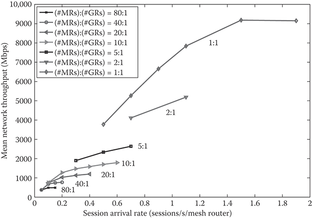
FIGURE 35.3 Mean network throughput versus session arrival rate under different gateway router topologies. In all cases, the routing metric “min_air-time” and the ACC scheme AC_RF is employed. (Adapted from H. Lee, Wireless mesh networks: Protocol design and performance evaluation, (Figure 5.3). PhD dissertation, Stanford University, Stanford, CA, USA, Mar. 2010.)
Figure 35.3 shows that the network throughput improves significantly as more GRs are deployed. There are two major factors that lead to such improvement. One is the shorter average path length, that is, fewer MRs, which each EU data go through to reach the backbone network. Another key factor is the fact that each GR serves fewer MRs on average, and thus each MR interacts with fewer other MRs. This leads to fewer constraints on the usage of a data time slot at an MR and in turn to increased reuse of each data time slot. With more deployed GRs, significantly more data time slots can be used simultaneously and each data time slot can be reused considerably more.
35.3.2.2 Per-Session Throughput
As seen in Figure 35.4, the mean per-session throughput generally decreases with the increasing session arrival rate given the network topology and the routing metric. The lower per-session throughput under a higher arrival rate results from a longer session delay, which is in turn attributed to two main factors: the lower mean PHY transmission rate on data time slots due to increased interference, and the longer delay in acquiring resources at MRs due to more EUs competing for the same resources. Figure 35.4 also demonstrates that for an admitted EU, a stable mean per-session throughput is provided under each session arrival rate and that the mean per-session throughput does not diminish even under heavy traffic loads. It also indicates that the mean per-session throughput considerably improves with more deployed GRs.
Due to the tree structure of the routing tables, the mean per-session throughput provided at an MR greatly varies depending on the path length from the MR to its best GR and the number of MRs served by the same GR. Generally, a significantly larger mean per-session throughput is provided at an MR that is fewer hops away from its best GR. As more GRs are deployed, the per-session throughput increases while the overall trend with the increasing session arrival rate remains the same under each GR topology scenario.
35.3.2.3 Blocking Rate
As seen in Figure 35.5, the blocking rate increases with the increasing session arrival rate given the network topology and the routing metric. This monotonicity follows from the fact that under a higher arrival rate, a new EU arriving to the network sees more EUs on average that are being served at the MR to associate with, and thus has a higher probability of being blocked. As the network starts to saturate with the increasing session arrival rate, the blocking rate increases very sharply as seen in Figure 35.5. This sharp increase results from the fact that the number of EUs supportable by the network saturates with the increasing arrival rate.

FIGURE 35.4 Mean per-session throughput for successfully completed sessions versus session arrival rate under different gateway router topologies. In all cases, the routing metric “min_air-time” and the ACC scheme AC_RF is employed. (Adapted from H. Lee, Wireless mesh networks: Protocol design and performance evaluation (Figure 5.6). PhD dissertation, Stanford University, Stanford, CA, USA, Mar. 2010.)
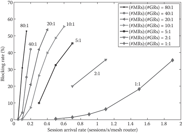
FIGURE 35.5 Blocking rate versus session arrival rate under different gateway router topologies. In all cases, the routing metric “min_air-time” and the ACC scheme AC_RF is employed. (Adapted from H. Lee, Wireless mesh networks: Protocol design and performance evaluation (Figure 5.8). PhD dissertation, Stanford University, Stanford, CA, USA, Mar. 2010.)
We also calculate the blocking rate for each MRn, where MRn denotes an MR that is n hops away from its best GR. The blocking rate at MR0 is significantly smaller than those at MRn, n > 0 in all cases. This is due to the fact that blocking at MR0 occurs only when there is no resource left for receiving data for a new EU. It turns out that MR0 still tends to have a few data time slots available for reception for a new EU even when the overall blocking rate becomes as high as 50%.
On the other hand, one has to consider two main factors to understand the blocking rates at MRn, n > 0. One factor is the amount of opportunity that MRn acquires for forwarding data, and the other factor is the amount of radio resources, that is, data time slots and the supportable PHY transmission rates over them, which are available at MRn. The chance or opportunity that MRn2 acquires for forwarding data is smaller than that of MRn1, n1 < n2. On the other hand, due to the tree structure of the routing tables, MRn2 serves fewer EUs on average and thus tends to have more available data time slots and higher supportable PHY rates than MRn1. Depending on the mesh size and the traffic load in the network, the blocking rate at MRn1 can be smaller or larger than MRn2. Please refer to [19] for more detailed discussions.
35.3.2.4 Dropping Rate
Recall that an EU releases a data time slot after a maximum number of unsuccessful retransmissions on the slot, and becomes dropped if it runs out of data time slots. The successive retransmission failures are primarily due to new interfering transmissions on the same data slot that were not seen when the data slot was assigned to this new EU. As seen in Figure 35.6, when the network is lightly loaded, the dropping rate generally increases with the increasing session arrival rate. This monotonic increase under light traffic loads follows from two factors: one is that there are more new transmissions on each data time slot when more new EUs are admitted across the network under a higher arrival rate. The other factor is that when the network is lightly loaded, the interference level on a data time slot is low enough so that multiple MRs across the network may see the same data time slot available and assign the slot to new transmissions.
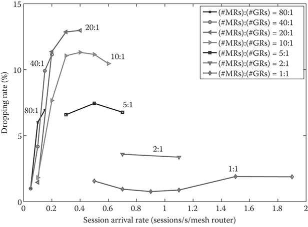
FIGURE 35.6 Dropping rate versus session arrival rate under different gateway router topologies. In all cases, the routing metric “min_air-time” and the ACC scheme AC_RF is employed. (Adapted from H. Lee, Wireless mesh networks: Protocol design and performance evaluation (Figure 5.10). PhD dissertation, Stanford University, Stanford, CA, USA, Mar. 2010.)
As the arrival rate keeps increasing and the network becomes increasingly saturated, the number of new EUs that are admitted at once across the network tends to saturate as well. Consequently, the probability of a new EU getting dropped due to additional new transmissions also tends to saturate. Furthermore, as seen in Figure 35.6, the dropping rate may even start to decrease with the increasing arrival rate in some cases. This decrease can be explained as follows. If the mesh size is small enough and the traffic load in the network is high enough so that the interference level on data time slots is too high for the same data time slot to be assigned to multiple new transmissions simultaneously, then, each data time slot assigned to a new EU or new transmission may not suffer from as much increase in the cochannel interference as it did under a lower arrival rate, leading to a decrease in the dropping rate.
We also calculate the dropping rate for each MRn. The dropping rate at MRn2 tends to be smaller than that at MRn1, n1 < n2. This is because MRn2 tends to have more available data time slots on average than MRn1, and thus a data time slot chosen for a new EU at MRn2 tends to have a lower interference level under the employed data time slot selection algorithm. The reason why the dropping rate at MR0 is noticeably higher than those at MRn, n > 0 is that the blocking rate at MR0 is significantly smaller than those at MRn, n > 0, and thus an admitted EU tends to get assigned data time slots with far stronger interference.
35.4 Conclusion
In this chapter, we focused on WMNs that serve as access networks over large geographic areas, and presented protocols and performance behavior that are based on more realistic models for physical and networking layers of network functions that have been often oversimplified in the literature. We first presented a set of MAC protocols that incorporate such models for the WMNs. We then presented the performance of the WMNs obtained through a large simulator that incorporates measurement-based models for radio propagation and interference calculation for a large built-in urban area. We first compared the impact of two ACC schemes on the network performance, and demonstrated that the ACC scheme AC_RF was able to stabilize the network even under heavy traffic loads. We then investigated the impact of different mesh sizes on the performance, and demonstrated that with more deployed GRs, that is, more backbone support to the network, the network throughput and per-session throughput improved significantly. Under each simulated scenario, we identified major factors that affect the performance behavior and showed that the PHY, MAC, and routing layers of network functions interact with one another in a complicated manner to determine the network performance.
References
1. I. Akyildiz and X. Wang, A survey on wireless mesh networks. IEEE Communications Magazine, 43(9), S23–S30, 2005.
2. R. Bruno, M. Conti, and E. Gregori, Mesh networks: Commodity multihop ad hoc networks. IEEE Communications Magazine, 43(3), 123–131, 2005.
3. M.J. Lee, J. Zheng, Y.-B. Ko, and D.M. Shrestha, Emerging standards for wireless mesh technology, IEEE Wireless Communications Magazine, 13(2), 56–63, 2006.
4. Google, Inc. [Online]. Available: http://www.google.com/corporate/.
5. Tropos, Inc. [Online]. Available: http://www.tropos.com.
6. E. Perkins, E. Belding-Royer, and S. Das. (2003, Jul.) Ad hoc on demand distance vector (AODV) routing. [Online]. Available: http://www.ietf.org/rfc/rfc3561.txt.
7. C. Perkins and P. Bhagwat, Highly dynamic destination-sequenced distance-vector (DSDV) routing for mobile computers. ACM SIGCOMM Computer Communication Review, 24(4), 234–244, 1994.
8. D. Johnson and D. Maltz, Dynamic source routing in ad hoc wireless networks. Mobile Computing, 353, 153–181, 1996.
9. T. Clausen and P. Jaquet. (2003, Oct.) Optimized link state routing protocol (OLSR). [Online]. Available: http://www.ietf.org/rfc/rfc3626.txt.
10. R. Draves, J. Padhye, and B. Zill, Comparisons of routing metrics for static multi-hop wireless networks. Prof. of ACM Special Interest Group on Data Communications Conference (SIGCOMM), pp. 133–144, Aug. 2004.
11. R. Draves, J. Padhye, and B. Zill, Routing in multi-radio, multi-hop wireless mesh networks. Proceedings of ACM Mobile Computing and Networking Conference (MOBICOM), Philadelphia, PA, pp. 114–128, Sep. 2004.
12. D. Couto , A high-throughput path metric for multi-hop wireless routing. Wireless Networks, 11(4), 419–434, 2005.
13. Z. Tang and J. Garcia-Luna-Aceves, A protocol for topology-dependent transmission scheduling in wireless networks. Proceedings of IEEE Wireless Communications and Networking Conference (WCNC), New Orleans, LA, pp. 1333–1337, Sep. 1999.
14. C. Zhu and M. Corson, A five-phase reservation protocol (FPRP) for mobile ad hoc networks. Wireless Networks, 7(4), 371–384, 2001.
15. C. Zhu and M. Corson, An evolutionary-TDMA scheduling protocol (E-TDMA) for mobile ad hoc networks, Proceedings of Advanced Telecommunications/Information Distribution Research Program (ATIRP), College Park, MD, Mar. 2000.
16. H. Lee and D. Cox, A fully-distributed control time slot assignment protocol for large wireless mesh networks. Proceedings of IEEE Military Communications Conference (MILCOM), San Diego, CA, Nov. 2008.
17. H. Lee and D. Cox, A fully cooperative and distributed medium access control protocol for large TDMA/TDD-based wireless mesh networks. Proceedings of IEEE Vehicular Technology Conference (VTC)-Spring, Barcelona, Spain, Apr. 2009.
18. H. Lee and D. Cox, Admission and congestion control for large-scale wireless mesh access networks. Proceedings of IEEE Wireless Communications and Networking Conference (WCNC), Sydney, Australia, Apr. 2010.
19. H. Lee, Wireless mesh networks: Protocol design and performance evaluation. PhD dissertation, Stanford University, Stanford, CA, USA, Mar. 2010.
20. I. Chlamtac and S. Kutten, A spatial-reuse of TDMA/FDMA for mobile multi- hop radio networks. Proceedings of IEEE Conference on Computer Communications (INFOCOM), Washington, DC, 1985.
21. I. Cidon and M. Sidi, Distributed assignment algorithms for multihop packet radio networks. IEEE Transactions on Computers, 38(10), 1353–1361, 1989.
22. A. Ephremedis and T. Truong, Scheduling broadcasts in multihop radio net works. IEEE Transactions on Communications, 38(4), 456–460, 1990.
23. S. Ramanathan, A unified framework and algorithm for channel assignment in wireless networks. Wireless Networks, 5(2), 81–94, 1999.
24. IEEE Std. 802.11, 1999 Edition (R2003), Information technology Telecommunications and information exchange between systems—Local and metropolitan area networks—Specific requirements—Part 11: Wireless LAN Medium Access Control (MAC) and Physical Layer (PHY) Specifications.
25. D. Zhao, J. Zou, and T. Todd, Admission control with load balancing in IEEE 802.11-based ESS mesh networks. Wireless Networks, 13(3), 351–359, 2007.
26. C. Zhu and M. Corson, Qos routing for mobile ad hoc networks, Proceedings of IEEE Conference on Computer Communications (INFOCOM), New York, NY, pp. 958–967, Jun. 2002.
27. I. P802.11s/D0.01, Draft Amendment to Standard IEEE 802.11: ESS Mesh Networking. IEEE, Mar. 2006, work in progress.
28. M. Bahr, Proposed routing for IEEE 802.11s WLAN mesh network. Proceedings of Wireless Internet Conference (WICON), Boston, MA, Aug. 2006.