Chapter 7
Operating Systems Overview
An operating system provides multiplexed access to shared resources that include peripherals, CPU, and memory. Multitasking creates the illusion that many concurrent threads of execution are running on the processor when in reality the operating system kernel interleaves their execution on the basis of a scheduling policy. This is effectively time division multiplexing of the CPU. The operating system provides mechanisms to interact with services through an application interface. It provides process management (creation, deletion, and so on) and schedules the execution of the processes. It provides memory management, thread synchronization primitives, and time of day services.
As an embedded systems designer you will also have to be aware of the device driver model supported by the operating system. Each operating system has its own pattern to implement a device driver, but they have many traits in common. This chapter describes each of these topics in detail, and where appropriate we will use examples from VxWorks and Linux to illustrate our points.
Application Interface
The operating system provides a series of service calls that allow applications to interact with the kernel. In many cases application writers do not make direct system calls, but instead rely on a set of libraries that provide a broad range of services to applications. Some of these libraries depend on making kernel services calls, while others do not require any interaction with the kernel.
The C library is a good example. The C libraries are defined by the C Library Standard under ISO/IEC 9899:1999 (commonly referred to as C99). The library provides functions such as string manipulation and parsing, memory copy, memory allocation, print formatting, and file I/O. Functions such as string and memory copy do not require any operating services; however, malloc() and file I/O such as printf() do require the use of OS services. A C language application can perform many functions without resorting to using any OS service calls directly. The most common implementation of the C library on Linux systems is the GNU C Library (GLIBC). In addition to complying with C99, the library provides services compatible with POSIX.1c, POSIX.1j, POSIX.1d, and Unix98, Single Unix Specification.
OS Application Interface
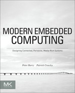
Let’s look at an example of implementation of malloc() found in GLIBC (http://www.gnu.org, glibc/malloc/malloc.c). The malloc() function maintains a number of buffers in fast bins. These are a small number of fixed buffer pools from which memory can be allocated when an application requires memory without having to make a system call. If the bins are empty or an allocation size request is larger than that supported by the bins, the malloc() function must make a request to the operating system to extend the process data segment. This is carried out by calling the sbrk() function, which is a wrapper to the system call brk(). The brk() call changes the location of the program break, which is defined as the end of the process data segment. This effectively allocates memory to the process. In some cases, the brk() call fails and the mmap() service call is used to request a number of pages allocated by the kernel and mapped to the process space. The malloc() call then allocates memory from this mapped pool for requests. Figure 7.1 shows the interaction between the application, library, and service calls.
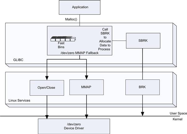
FIGURE 7.1 GLIBC and Service Calls.
The mechanism shown in Figure 7.1 is one of the most advanced scenarios; in embedded systems running an RTOS the implementation is simpler. For example, in VxWorks™ at the time of system initialization the malloc() library creates a number of fixed-size buffers pools. The malloc() call attempts to allocate from one of these buffer pools, and if this fails it will attempt to allocate from the system pool.
OS Service Calls
The operating system services are exposed through function wrappers provided as part of the POSIX/C Libraries. The general design pattern used for service calls is as follows (using Linux as an example).
1. Each service call has a user space library wrapper providing a function for each call.
2. Each service call is assigned an operating system service identifier in the form of an integer. The assignment of numbers for each service call is done by the maintainer of the operating systems. The previously allocated numbers do not change or get reassigned because doing so could break existing applications or libraries, that is, it would break backward compatibility
3. The service wrapper call pushes the calling arguments on to the stack, loads a register (eax for IA-32 platforms) with the service number for the call, and issues a service trap (or software interrupt depending on the target processor architecture).
4. The trap is an instruction that causes transition from the current user space execution to the function in the exception vector table, with the associated increase in privileges.
5. The system services trap handler dereferences a system call table using the service call number and transfers control to the function bound to the table.
6. At this point, the processor is executing the kernel system call function with kernel privileges.
Figure 7.2 shows the design pattern used by most operating systems when providing service calls.
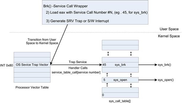
FIGURE 7.2 Service Call Design Pattern.
Processes, Tasks, and Threads
An operating system defines a minimal execution context that can be scheduled. Depending on the operating system, they are called tasks or threads. In an RTOS, the system is normally composed exclusively of tasks. Each task contains task-specific context or state. All tasks are generally globally visible with relatively easy access to shared memory between tasks. The task view is flat across the operating system; the primary difference between tasks performing kernel type work and application work are the privilege and priority of the tasks. In recent versions of VxWorks a process concept was introduced in which tasks are assigned to a virtual memory context and do not have global visibility of memory. In the case of more general-purpose operating systems one or more threads are incorporated to execute under a user space process. Threads within a process share the same memory space, descriptors for access to system resources, and the like. In Linux, threads are created within a process through the fork system call, although in most cases programmers use the pthread library to create and manage threads. The kernel threads are not unlike the task equivalent in the VxWorks RTOS case; there is no protection mechanism between the kernel threads and they have access to the kernel memory map. Figure 7.3 shows examples of the differing configurations. In the case of threads created as part of a user space Linux process, the threads are similar to those found in the kernel, but they share the memory space, file descriptors, and signal handles of the process to which they are assigned.

FIGURE 7.3 Tasks, Threads, and Processes.
In both VxWorks and Linux the scheduling unit in the operating system is the task or thread.
In the case of VxWorks and many other real-time operating systems the task creation is explicitly under control of the application. An initial root task is created by the kernel. The kernel root task starts with the highest privileges. The root task subsequently creates a number of other task and then deletes itself (frees all resources associated with it). Each of the threads can create new threads using the taskOpen() function call. The taskOpen() function call takes the following arguments:
• Name—A character string that can be displayed by debug functions or used to obtain a handle for a task. There are public and private task name spaces.
• Priority—A value ranging from 0 to 255, with 0 being the highest priority.
• Task options—Indicate whether the task uses floating point, private or public task, some stack fill and protection options, and a flag to indicate whether the thread should start on creation or be created in a suspended state to be started explicitly later.
• Mode—Indicates whether a new task is to be created or just a search for an existing task.
• Stack base—Allows the stack to be placed at a particular address; if NULL is specified, the kernel will allocate stack space. In embedded systems, this is often useful as you may place the stack for a real-time process in a dedicated on-die SRAM. This improves determinism and is often important for interrupt tasks.
• Stack size—This is the size of the stack to be used for the task; if stack base is NULL, this will be allocated. As resources can be quite limited in embedded systems, the maximum size of the task must be specified at the time the task is created and it is allocated at that time.
• Context—This is a pointer to an object that is stored by the kernel for this task. VxWorks does not use it directly. You should consider this to be a cookie; it can be used to store application-specific data for this task. This design pattern is often used in embedded systems.
• Function pointer—Starting function address for the task. When the task first starts to execute it will start to execute at this address.
• Arguments to task—The call supports providing up to 10 integer arguments to the task. The arguments are available to the function once the function is started. This allows you to create a number of different threads using the same function but have them behave differently depending on the arguments supplied.
The function returns a TaskID number. This task ID can be used for many low-level control functions such as the task activation call taskActivate() or other control functions to change priority, task deletion, and the like. As you can see, the creation of a task in an RTOS offers considerable flexibility for the behavior of the task when it is created and subsequently once it exists.
The pattern above is quite common for operating systems; the equivalent call in the Linux kernel is kernel_thread(). The function takes a function pointer for the entry point to the thread, a number of arguments that are passed to the threads entry point, and a number of configuration flags to indicate what aspects of the system should be shared (such as memory space).
Task Context
Each task or thread has a context store; the context store keeps all the task-specific data for the task. The kernel scheduler will save and restore the task state on a context switch. The task’s context is stored in a Task Control Block in VxWorks; the equivalent in Linux is the struct task_struct.
The Task Control Block in VxWorks contains the following elements, which are saved and restored on each context switch:
• The task program/instruction counter.
• Virtual memory context for tasks within a process if enabled.
• Non-core CPU registers, such as SSE registers/floating-point register, are saved/restored based on use of the registers by a thread. It is prudent for an RTOS to minimize the data it must save and restore for each context switch to minimize the context switch times.
• I/O assignments for standard input/output and error. As in Linux, a tasks/process output is directed to standard console for input and output, but the file handles can be redirected to a file.
• A delay timer, to postpone the tasks availability to run.
• A time slice timer (more on that later in the scheduling section).
• Signal handles (for C library signals such as divide by zero).
• Errno—the C library error number set by some C library functions such as strtod().
Task State and State Transitions
A task can be in one of a number of states. The kernel maintains the task state and transitions from one state to another. In the case of VxWorks, a task initially starts in the suspended state. When the task is activated it transitions to the ready state. The ready state does not mean the task is actually running; it is available to be run by the scheduler. Table 7.1 shows the task states that are supported by the VxWorks kernel but are representative of other operating systems.
Table 7.1. RTOS States
| State | State Description |
| Ready | The task is not waiting for any resource other than the CPU. |
| Pending | The task is blocked due to the unavailability of some resource. For example, the task could be blocked waiting for the release of a semaphore from another task, or waiting for input. |
| Delayed | The task is waiting on a timeout and is sleeping. |
| Suspended | The task is unavailable for execution (but not pending or delayed). This state is used primarily for debugging. Suspension does not inhibit state transition, only execution. Thus, pending-suspended tasks can still unblock and delayed-suspended tasks can still awaken. |
| Stop | The task is stopped by the debugger. |
| Pending + T | The task is pending with a timeout value. |
| Other state combinations with Suspend and Stop | The kernel maintains a number of combination states that are combined with Stop and Suspend states, for example, Stop + Pending + Stopped, indicating the task is pending, suspended, and stopped by the debugger. |
| State + Inherited Priority | All states can be augmented with an inherited priority. The kernel supports a mechanism to increase of priority to prevent a condition known as priority inversion, described later in the scheduling section. |
The state transitions are managed by the kernel. Figure 7.4 shows the state transitions and a selection of events that trigger the state transitions in normal operating (non-debug) scenarios.
FIGURE 7.4 RTOS State Transitions.
The transition between ready and pending is the most common transition for a task in an embedded application. Examples are given in the diagram of the use of semaphore and message queues. The semTake call attempts to get a semaphore. If the semaphore can be acquired (no other task has acquired it), then the task continues without blocking. If, however, another task has ownership of the semaphore, the task will block and be placed into the pending state. When the owner of the semaphore releases it, it allows the requesting task to transition to the ready state. At some point the kernel will schedule that ready task for execution. The message send and receive has a similar state transition sequence. A receiving task will typically make a blocking call to a message queue receive function. The task will block (be placed into the pending state) if there are no messages in the queue. When another task places a message in the queue, the message receive task will transition from pending to ready. Each state is typically maintained as a queue data structure, where tasks/threads in each state are in the appropriate queue; for example, the Ready Queue contains all tasks/threads that are in the read state.
Scheduling
The scheduler in the operating system selects a task/thread from the available list of ready tasks and starts the execution of the task. A number of different scheduler types are used in operating systems with varying characteristics. We will discuss the simple scheduler, round-robin scheduler, preemptive priority scheduler, and completely fair scheduler.
Simple FIFO Scheduler
The most basic scheduler selects a task from the top of a ready queue and transfers control to the task. No scheduling decision is made until the running task relinquishes control by generating an event that causes the task to block (no longer ready) or the task explicitly yields the CPU using a yield call. A yield call is an explicit notification to the scheduler that it can take an opportunity to reschedule another task if one is ready. The operating system does not preempt the currently executing task; this scheduling schemes is often called cooperative scheduling. In many cases a yield call is implemented as a system delay call with a timeout of zero. When a task becomes ready it is simply added to the end of the ready queue. The scheduler picks the task from the top of the queue to run. Simply put, the first task to enter the ready queue is the first to be scheduled (first in, first out, or FIFO). The coding of such tasks requires detailed knowledge of all other tasks in the system if appropriate system behavior is to be achieved. This scheme works on only the simplest of systems. Figure 7.5 shows the wide range of times that are allocated to each task due to the sequence blocking and yield calls.
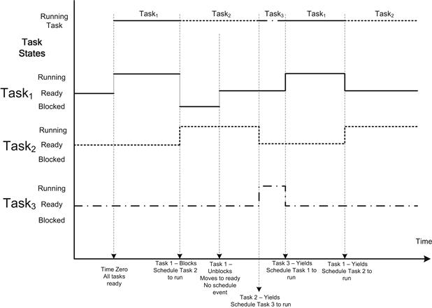
FIGURE 7.5 Nonpreemptive FIFO Task Scheduling.
This form of scheduling was prevalent in the past. The code was often developed by the system developer and no use of an RTOS/OS was made. The execution time of a task in this model is completely dependent on the time when the task is run to the time it blocks or yields. Tuning such a system to ensure the appropriate system behavior can be very challenging; the introduction of a new task can perturb the other tasks’ behavior to an extent that the system no longer functions as required.
Round-Robin Scheduler with Priority and Preemption
A priority-based preemptive scheduler preempts the currently executing task when a task of higher priority than the current task running transitions to the ready state. Thus, the kernel ensures that the CPU is always allocated to the highest-priority task that is ready to run. When a higher-priority task (than the current running task) changes state from blocked to ready, it will start executing. The transition from blocked to ready may be due to reception of a message in the queue, acquiring a semaphore, a timeout event, or reception of some data from an I/O device. In all such operating system events the scheduler evaluates the task states and priorities. The disadvantage of this scheduling policy is that when multiple tasks of equal priority must share the processor, if a single task is never blocked it can usurp the processor. Thus, other equal-priority tasks are never given a chance to run.
In order to ensure that equal-priority tasks are guaranteed to share the processor, an extension of the priority scheduler is introduced, namely, round robin. The round-robin scheduler shares the processor using a time-slicing algorithm between the equal priority tasks. When the OS timer expires, the scheduler is executed. The scheduler switches between equal priority tasks (unless a higher-priority task becomes ready) on each OS time slice. The time slice corresponds to one or more OS timer periods and is configured as part of the RTOS. Note that the OS timer also causes an evaluation of the operating system timers, and an expired timer could result in a task moving from blocked (pending timeout) to ready, and if this is the highest-priority task, it will run. No task gets a second slice of time before all other tasks in the priority group have been allowed to run.
The selection of the OS timer period is a critical aspect in an embedded operating system. The typical timer period in an RTOS is 1 ms; that is, the timer frequency is 1000 Hz. The equivalent timer period on a general purpose OS is usually less. The Linux kernel as of 2.6.36 provided configuration options for 100 Hz, 250 Hz, 300 Hz, and 1000 Hz, with the default option set to 250 Hz.
The combination of both preemption and round-robin scheduling provides very effective control of the behavior of a real-time system; however, the selection of priorities for the tasks is a skilled exercise to ensure the appropriate behavior of the system. Figure 7.6 shows an example of the task states and run order.

FIGURE 7.6 Round-Robin Scheduler with Preemption and Priority.
The round-robin scheduler with preemption and priority is the traditional schedule enabled in VxWorks by default.
Note
Protection of data structures: if two tasks have access to a shared data structure (such as a linked list), it is important to always protect access to the structure by using synchronization primitives to ensure atomic updates. Operating system preemption could cause a context switch at any point in the data structure update, which could result in an incorrect update.
Linux Kernel’s Scheduler
The Linux scheduler has to support a very wide range of scenarios, from single-processor to multiprocessor systems, from workstation high-compute workloads to the low-latency interactivity requirements for user interfaces and a wide range of processor performance ranges. The scheduler has continued to evolve to meet this broad range of requirements. The original Linux 2.4 scheduler was nonpreemptible and only supported real-time scheduling with a separate patch. As the kernel transitioned to 2.6, the scheduler was enhanced to support preemption and real-time tasks; the latest change has been the introduction of the completely fair scheduler (CFS) in version 2.6.23 of the kernel. The completely fair scheduler is primarily a “desktop” scheduler, although it has many mechanisms to control its behavior (http://lxr.linux.no/linux+v2.6.37/Documentation/scheduler/sched-design-CFS.txt#L214).
The following function controls the behavior of processes scheduling discipline:
int sched_setscheduler(pid_t pid, int policy,
const struct sched_param
∗param);
There are real-time and non-real-time disciplines. For the non-real-time processes, you can select one of the disciplines that are scheduled by the CFS:
• SCHED_NORMAL—The standard round-robin time-sharing policy, used for regular tasks.
• SCHED_BATCH—For batch-style execution of processes. It is does not preempt as often as a NORMAL task, allowing them to run longer; this has an impact on the overall interactivity of the system.
The vast majority of threads in a system are scheduled under one of the disciplines defined by the completely fair scheduler. Threads can also be scheduled under one of the real-time disciplines. All ready real-time threads are scheduled to execute before NORMAL/BATCH and IDLE threads. There are two real-time disciplines that can be selected:
The priority of a process scheduled with SCHED_FIFO and SCHED_RR dictates when a thread will be scheduled, with priorities ranging from 1 (low) to 99 (high) priority. The priority of these real-time processes is always higher than the NORMAL/BATCH and IDLE scheduled processes. For embedded applications it is important to use the appropriate scheduling discipline and thread priorities.
Real-time processes are always scheduled to run over any “normal” process, simply because the priority is not zero. As soon as any real-time process becomes ready it will preempt the normal process (SCHED_OTHER). The SCHED_FIFO discipline is a very simple scheduling algorithm. It does not time slice between processes at the same priority. When a SCHED_FIFO process first becomes ready, it is placed at the end of the run queue for that particular priority. Processes of higher priority preempt lower-priority process. A preempted process will still be at the head of the ready queue when the higher-priority process blocks. A yield call will place the currently executing process at the end of the run list for its priority level. The process remains available to run unless it blocks. The SCHED_FIFO_RR is similar to the SCHED_FIFO; however, execution of a SCHED_FIFO_RR process is allocated a time quantum. When the quantum expires, the scheduler de-schedules the process and puts it at the end of the run list for that priority level. The process remains ready to run. If a SCHED_FIFO_RR process is pre-empted by a higher-priority process, its quantum counter is suspended, and it will be allowed to execute the remainder of its quantum when the higher-priority process blocks. See the Linux main page for sched_setscheduler for more details.
Although the Linux kernel (as of 2.6) is often stated to be preemptible, the behavior of the scheduler is in actuality configurable. The kernel has three options to control preemption.
• CONFIG_PREEMPT_NONE—This sets the scheduler as nonpreemptible and is often set for servers where we want to maximize the overall work done by the CPU by reducing context switches. In this case kernel processes are not subject to preemption.
• CONFIG_PREEMPT_VOLUNTARY—This allows kernel threads to voluntarily be preempted. This controls the behavior of the might_preempt() call.
• CONFIG_PREEMPT—This makes kernel threads fully preemptible, unless a thread is holding a kernel lock.
POSIX-Compliant Scheduler
POSIX standardized a wide range of service APIs, and APIs are defined to create POSIX threads; the standard defines how the threads should be scheduled. The POSIX:2008 standard the Open Group Base Specifications Issue 7IEEE Std 1003.1™-2008 can be found here: http://pubs.opengroup.org/onlinepubs/9699919799/.
As in Linux, the scheduling disciplines are SCHED_FIFO, SCHED_RR, and SCHED_OTHER. In the SCHED_FIFO the thread waiting the longest is processed first; for the SCHED_RR thread, the behavior is the same as that defined by the Linux kernel. VxWorks also offers a POSIX-compliant scheduler (although it is not the default configuration).
Scheduler Complexity
The time taken to select the next task/thread to run with respect to the number of tasks in the system is an important characteristic of a scheduler. As with many algorithms, big O notation is used to describe this aspect of a scheduler.
• O(1) scheduler—This scheduler takes a constant amount of time to select a task to run regardless of the number of tasks/threads to select. The scheduler used in Linux versions prior to 2.6.23 used a O(1) order scheduler.
• O(log N) scheduler—The scheduler evaluation time increases with the log of the number of tasks. The Linux scheduler post 2.6.23 is known as the completely fair scheduler. The selection of the run tasks occurs in O(1); however, the tasks are placed into a red-black self-balancing binary tree that takes O(log N) time, so the algorithm is considered to be of O(log N) complexity.
Note that no specific performance attributes are associated with the classification; it merely represents the relative performance of the scheduler as the number of tasks increases.
Memory Allocation
All systems provide a mechanism to allocate memory to an application. Functions are provided to allocate and free memory from the system heap. In the case of the C language, the C language library provides the functions to manage the memory allocation. In this case the calls are malloc() and free().
An embedded system may support individual heaps per process, with separate maximum heap sizes assigned to each process. Other configurations have a single heap in the system, where all tasks may allocate from and free to. In the case of the process view, the memory allocation functions return a virtual address that is only valid for the process making the call. In a flat model, the memory allocated is globally visible. It is not uncommon for embedded applications to pass messages between tasks that contain pointers to memory that is allocated using malloc() calls. To access memory allocated by another task, the system must use a flat memory model or use special shared memory APIs to facilitate the sharing of allocated memory across tasks.
The memory allocation system has no prior knowledge of the sequence of memory allocations and frees that might be requested by applications. The allocator algorithms attempt to maximize the size of contiguous blocks within the heap over time to ensure that the heap does not get fragmented. A fragmented heap is one in which a significant amount of memory is free but the size of any contiguous section is small. In this case an application request to allocate memory can fail. Allocator algorithms can help significantly to reduce fragmentation. Figure 7.7 shows an example of how a heap may be fragmented through a series of allocation and free calls.

FIGURE 7.7 Fragmented Heap (Zebra Pattern).
To help achieve this many memory allocations, schemes partition the heap into a number of fixed-size pools and a single large variable-size pool as shown in Figure 7.8. The pools are often referred to as power of two pools, as the entry sizes increase with power of two (for example, 32, 64, 128 bytes).
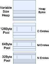
FIGURE 7.8 Power of Two Heap.
When an application makes a request for a number of bytes, for example, 64 bytes, the allocator first attempts to allocate from the 64-byte pool. If that fails, it tries the next size pool, and so on. If allocation fails for all the fixed-size pools, then the allocator allocates from the variable-size heap. The number of fixed-size pools, the size of the entries in a pool, and the number of entries in each pool are configurable and should be tuned for your embedded application. In embedded applications it is very important to manage possible heap fragmentation. Embedded systems can remain running without restarting for very long periods of time (up to years). The mallopt() call in the C library can be used to tune the behavior of malloc/free.
Despite the techniques described here, over time the pattern of allocation and free may result in fragmentation of the variable-size heap. For embedded systems, it is best practice to pre-allocate all memory requirements for applications at the time of startup and subsequently manage the allocated memory in the form of memory pools. Many real-time operating systems provide APIs to create and manage such pools; it is strongly advised to use such techniques in embedded systems. The Linux kernel uses such techniques in the slab memory allocator.
Virtual Memory and Protection
When process level memory protection is employed, the memory addresses allocated to the process are virtual addresses in the process space. The memory management unit (MMU) and associated page tables manage the translation between code, data, and heap process memory to the underlying physical memory. Each process appears to live in the same virtual address space, but actually resides in different physical areas of memory. Figure 7.9 shows how memory regions in a process are mapped to physical memory.
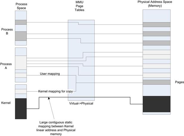
FIGURE 7.9 Address Space Mapping to Physical Memory.
The operating system manages the page tables based on process creation and underlying kernel services calls. Each process has an active page table in context when the process is executing. The CPU contains a process ID register (CR3 on Intel architecture) that is used to select the appropriate tree within the page table hierarchy. One of the tasks the operating system performs is to update the CR3 value in the CPU during context switches. The mapping between process address space and physical pages is often highly fragmented; there is no mathematical correlation between the virtual and physical address (it must be identified via page table lookup). On the other hand, in many systems, the page tables configured to map kernel space usually map a large, virtually contiguous area within the kernel to a large, physically contiguous area in physical memory. This simplifies the calculation/translation between kernel virtual and physical address for the kernel mappings. The addition/subtraction of an address offset can be used to convert between kernel virtual and physical addresses. However, this should not be relied upon. You must always use OS-provided functions to translate addresses. This attribute is a system optimization to make the translation as efficient as possible.
In full-featured operating systems, the physical memory pages may be copied to a storage device. This process is known as swapping. The virtual to physical mapping for the process physical page will be removed. When an application attempts to access the virtual address that previously had a physical page mapped, the MMU will generate a page fault. The page fault handler copies the page from the drive into memory (not likely to be the same physical memory used previously), sets up the correct page mapping, and returns from the page fault exception, at which point the instruction that generated the fault is re-executed, this time without faulting. In many embedded systems, there is no swap storage and swapping is disabled.
Some embedded systems have no memory management unit. In this case the virtual and linear address spaces are mapped 1:1. Each process must be created and linked to a target physical address range in which it will reside during runtime. There is far less protection (code from one process can access/destroy memory belonging to another process) between processes if there is no MMU in the system, although some systems do implement a memory protection unit to prevent processes from accessing other processes’ memory, but these are limited to a small number of protection regions. Most real-time operating systems support embedded processors with or without an MMU; there is also a variant of Linux known as uCLinux (http://www.uclinux.org) that does not require an MMU.
Buffers allocated to a process cannot be shared between processes, as the physical memory backing the malloc() call is only allocated to the process that allocates it. There is also a series of calls that can be used to allocate memory that is shared between processes. Figure 7.10 shows the series of calls to allocate a 4-K page of memory between two processes. The calls must be coordinated by both processes.
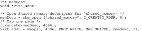
FIGURE 7.10 Shared Memory Allocation.
The shared memory is set up by creating two different contiguous virtual memory mappings for one set of physical memory pages.
Freeing Memory
In embedded systems the memory allocated by a task may not be automatically freed based on the deletion of that task; this is in contrast to a process model in an operating system such as Linux where all memory associated with a process is automatically returned to the kernel when a process is terminated. For embedded tasks, it is important to keep track of all the memory allocated by the task if you expect to be able to destroy and restart it. In many cases, a memory allocation wrapper is used. The wrapper places the pointer allocated to the task in a linked list that can be used to ensure that all resources are freed when the task is destroyed.
Swapping Memory
On most desktop systems, the memory associated with a process may be swapped out to mass storage when the process is not active. It allows the system to allocate more virtual memory to applications than the total amount of physical memory. In fact, the space allocated for swapping memory pages from an application is usually set to twice the amount of physical memory. The swapping process only applies to user-level applications. Kernel memory is never swapped.
Memory swapping is rarely used in embedded systems, because it introduces additional wear on the file system (often based on flash solid-state devices) and also introduces a level of non-determinism to applications. Few real-time operating systems actually support swapping, and swapping can be disabled in Linux by not setting the Linux kernel build option CONFIG_SWAP. The function mlockall() can also be used to lock all pages mapped into the address space of the calling process.
Clocks and Timers
Timer and clock services are capabilities offered by an operating system. In embedded applications a task may need to issue a delay/sleep for a period of time or manage the generation of events at a particular rate. To facilitate such cases, the platform provides counters and timers. A timer is typically a hardware resource that generates an interrupt to the processor at a periodic rate. Counters are hardware resources that are clocked at a particular rate and can be read by the software to establish the amount of time that has passed.
All operating systems make use of at least one timer called the system tick. This timer is used to trigger timer callback functions and provide the time base to support time slicing of tasks by the OS scheduler.
Synchronous Execution
Many OS service calls provide an argument to specify a timeout. The execution context is delayed or suspended for a period of time. For example, OS calls used to wait for events such as a message on a queue or a socket select call provide an argument to timeout and return without having received any data. The VxWorks call to wait for a message on a queue is as follows.
int msgQReceive(
MSG_Q_ID msgQId,/∗ message queue from ∗/
char ∗ buffer, /∗ buffer to receive message ∗/
UINT maxNBytes, /∗ length of buffer ∗/
int timeout ) /∗ ticks to wait ∗/
The operating system also provides calls such as sleep(), nanosleep(), uDelay(), and mDelay() that delay the calling task by a specified amount of time. If the time is long enough the call may actually de-schedule the task, and the operating system will place it on the ready queue after the specified delay. In simple executives, a sleep(0) call is the same as a yield() call explicitly requesting that the OS scheduler review the list of ready tasks and reschedule if appropriate.
Asynchronous Execution
Operating systems also provide services to cause the execution of a function asynchronously to the main tasks after a defined delay. For example, user space applications in Linux/VxWorks can request that a SIGNAL be sent to an application (task) after a specified period of time using the alarm() call. The application must register a callback function for the SIGALARM signal. The operating system generates a SIGALARM to the application after the specified number of seconds expires. This mechanism only offers granularity of one second and is not very useful for embedded application use.
In the case of the Linux kernel and many real-time operating systems, a generic service is provided to schedule a callback function after a specified delay or periodically. The operating system maintains a list of callback functions and an associated timeout time in the future. Each time the OS tick timer expires, the timer list is reviewed and any callbacks that have an expiry time that is less than or equal to the current time count are called. The callback functions are often called in the context of the timer interrupt or timer thread. It is good practice to limit the amount of time spent in these callback functions, as lengthy callbacks affect the execution of the other callbacks. In most cases the callback is used to indicate to another thread that the timeout has occurred. For example, the callback function could send an event to another task or release a semaphore held by another task.
The Linux kernel offers timer services using the init_timer(), add_timer(), and del_timer() calls. The init_timer call is provided with a function pointer, a delta expiry time in jiffies, and data to pass to the callback function when the timer expires. In Linux a jiffy is the unit of time the scheduler operates on, by default 4 ms when the system is configured to schedule at 250 Hz. The add_timer() call schedules the timer to expire in the future at delta expire jiffies from when the add_timer() call occurs. The timer callback function is called in a separate context to the add_timer() call. These calls can be used by device drivers to perform simple polling behavior of a device, such as to check the link state of an Ethernet cable.
Depending on how the timer callback service is implemented, the calling context for the callbacks may have restrictions on what behavior is allowed within the function. In the case of Linux, in_interrupt() and in_atomic() are two calls you can use to establish whether you can make certain OS calls in the callback. In many embedded cases, you will know the context at design time and ensure the callback does not call any inappropriate calls. Although it is a good idea to use calls such as in_interrupt() for debug images, the system may evolve over time. If the underlying OS assumptions change, it is very difficult to debug cases where the callbacks make calls that are not allowed in the calling context.
Time of Day
Most operating systems provide time of day services. This is the real-world date and time of the platform. The operating system can maintain this in one of two ways. The first is to read a Real-Time Clock (RTC). A RTC is a hardware timer that is typically backed up by a battery and is maintained even when the platform power is removed. The RTC provides date, time, and alarm services. The second option is where the time is maintained by the CPU while the CPU is running. In this case the operating system uses a timer interrupt (perhaps the operating system tick timer) to count interrupts and increment the time. The time and date value must be seeded when the platform first starts-ups as it is not retained when no power is applied. In embedded systems, the initial time may be seeded using the RTC mentioned above or it may be acquired from an external source. A platform can acquire time from many external sources; the most frequent method is to obtain the time from a network source using Network Time Protocol (NTP). This protocol allows a network time server to provide time updates to clients with very high precision. The NTP is used not only to seed the initial time on a platform but also to ensure that an accurate time is mainlined over time (bearing in mind that the local oscillators on an embedded platform may not be very accurate.). In mobile systems, a very accurate time may be obtained from the cellular radio network.
The concept of time on Unix/Linux systems is represented by a counter that counts seconds since the epoch. The epoch is defined (by POSIX 2008 standard) as midnight Coordinated Universal Time (UTC) of January 1, 1970. The POSIX function time_t time(time_t ∗tloc) returns a type time_t, which represents the number of seconds since the epoch. Most operating systems provide functions to convert this value into other forms, such as the function asctime(), which converts the time in seconds to a string.
The granularity of time offered by the time() API is seconds. In many cases you will require a more precise copy of time, such as microseconds. The POSIX standard defines the following APIs to address this requirement:
• clock_getres() returns the resolution for a particular timer source, for example, the CLOCK_REALTIME (system time).
• clock_gettime()/clock_setime() get and set the time source specified in the API (for example, the real-time clock).
These calls both indicate the resolution and return the time to the appropriate resolution. At the time of writing, Linux 3.x reported a resolution of 1 ns, as shown by the code in Figure 7.11.
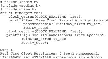
FIGURE 7.11 Get Resolution of Time on Platform.
Mutual Exclusion/Synchronization
In many cases it is critical to ensure serialized atomic access to resources such as data structures and/or physical device resources. There are many mechanisms to ensure mutually exclusive access to a resource. The first is to serialize access to the area where atomic updates must occur. An example of a critical section is when the execution context updates a counter in memory or performs pointer updates associated with insertion/removal of a node in a linked list.
When an execution context is performing the atomic update to a resource, it must prevent execution of any other context that might update the resource.
The simplest mechanism is to prevent the scheduling of any other execution context while the update is occurring. In many simple embedded systems, this was often carried out by disabling interrupts. This is not recommended, as it perturbs real-time behavior, interacts with device drivers, and may not work with multi-core systems. Disabling interrupts effectively prevents an operating system–triggered rescheduling of the task running in the critical section. The task must also avoid any system calls that would trigger execution of the OS scheduler. There may also be an operating system call to suspend scheduling of other tasks. Such mechanisms are blunt instruments to ensure mutual exclusion, as they may have a broad system wide impact. These techniques also do not work when being used by user- or de-privileged contexts such as a POSIX thread.
In many systems a hardware mechanism is provided to perform an atomic update in system memory. Processor architectures provide instructions to build mutual exclusion primitives such as Compare and Swap (CAS) and Compare and Exchange (CMPXCHG) in Intel Architecture and load-link/store-conditional instructions on PowerPC, ARM and MOPS architectures. These are sometimes referred to as atomic test and set operations. As an example, we describe how the CAS instruction can be used to perform an atomic update from two execution contexts. The CAS instruction compares the memory location with a given value. If the value at the memory location is the same as the given value, then the memory is updated with a new value given. Consider two execution contexts (A and B) attempting to update a counter: context A reads the current value, increments the current value by one to create the new value, then issues a CAS with the current and new values. If context B has not intervened, the update to the new value will occur, as the current value in memory is the same as the current value issued in the CAS. If, however, context B reads the same current value as context A and issues the CAS instruction before context A, then the update by context A would fail, as the value in memory is no longer the same as the current value issued in the CAS by context A. This collision can be detected because the CAS instruction returns the value of the memory; if the update fails then context A must try the loop again and will mostly likely succeed the second time. In the case described above, context A may be interrupted by an interrupt and context B may be run in the interrupt handler or from a different context scheduled by the operating system. Alternatively, the system has multiple CPUs where the other CPU is performing an update at exactly the same time.
Using a technique similar to the one described above, we can implement a construct known as a spin lock. A spin lock is where a thread waits to get a lock by repeatedly trying to get the lock. The calling context busy-waits until it acquires the lock. This mechanism works well when the time for which a context owns a lock is very small. However, care must be taken to avoid deadlock. For example, if a kernel task has acquired the spin lock but an interrupt handler wishes to acquire the lock, you could have a scenario where the interrupt hander spins forever waiting for the lock. Spinlocks in embedded systems can create delays due to priority inversion and it would be good to use mutexes where possible.
In reality, building robust multi-CPU mutual exclusion primitives is quite involved. Many papers have been written on efficient use of such resources to update data structures such as binary counters, counters, and linked lists. Techniques can be varied depending on the balance of consumer versus producer contexts (number of readers and writers).
The mechanism described above does not interact with the operating system scheduling behavior and the mechanism is not appropriate if the work to be performed in the critical section is long or if operating system calls are required. Operating systems provide specific calls to facilitate mutual exclusion between threads/tasks. Common capabilities provided include semaphores (invented by Edsger W. Dijkstra), mutexes, and message queues.
These functions often rely on underlying hardware capabilities as described above and interact with the operating system scheduler to manage the state transitions of the calling tasks.
Let’s describe a time sequence of two contexts acquiring a semaphore. Assuming context A has acquired a semaphore and context B makes a call to acquire the same semaphore, the operating system will place task B into a blocked state. Task B will transition to a ready state when task A releases the semaphore. In this case the system has provided the capabilities for the developer to provide mutual exclusion between task A and task B. Figure 7.12 shows the timeline associated with semaphore ownership.
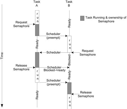
FIGURE 7.12 Semaphore Timeline.
As you can see, the operating system scheduler ensures that only one task is executing in the critical section at any time. Although we show task A continuing to run after the semaphore is released until it is preempted, in many operating systems the call to release the semaphore also performs a scheduling evaluation and the transition to task B (or other task) could occur at that point.
Note
Priority inversion is a situation that can occur when a low-priority task is holding a resource such as a semaphore for which a higher-priority task is waiting. The high-priority task has effectively acquired the priority of the low-priority thread (thus the name priority inversion). Some operating systems automatically increase the priority of the lower-priority thread to that of the highest-priority waiting thread until the resource is no longer owned by the low-priority thread.
In the case of VxWorks, the mutual-exclusion semaphore has the option SEM_INVERSION_SAFE. This option enables a priority inheritance feature. The priority inheritance feature ensures that a task that holds a resource executes at the priority of the highest-priority task blocked on that resource.
There are two different types of semaphore, namely, binary and counting. Binary semaphores are restricted to two values (one or zero) acquired/available. Counting semaphores increment in value each time the semaphore is acquired. Typically the count is incremented each time the semaphore is acquired or reacquired. Depending on the operating system the semaphore can only be incremented by the task/thread that acquired it in the first place. Generally speaking, a mutex is the same as a binary semaphore. Although we have discussed semaphores in the context of providing mutual exclusion between two threads, in many real-time operating systems a semaphore can also be used to synchronize a task or thread, and in essence indicates an event. Figure 7.13 shows a simple case where a task is notified of an event by an interrupt handler (using VxWorks calls).
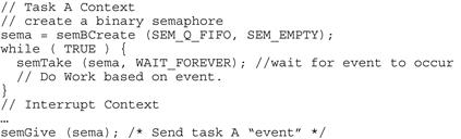
FIGURE 7.13 Task Synchronization.
As an embedded programmer, you have to be very aware of the services you can use in an interrupt handler. The documentation associated with your RTOS/OS should be referenced; making an OS call in an interrupt handler that is illegal can result in very strange behavior at runtime.
A common alternative to using mutual exclusion primitives to serialize access to data structure is to nominate a single entity in the system with responsibility to perform the updates. For example, a database structure can be abstracted by a messaging interface to send updates and make inquiries. Since only one thread is operating on the data at any time, there is no need for synchronization to be used within this thread. This can be a beneficial approach especially if the software was not originally designed to be multi-thread safe, but it comes at the higher cost of messaging to and from the owning thread. This technique can also be used to create a data structure that is optimized for a single writer and multiple readers. All writes to the data structures are carried out by a single thread that receives messages to perform the updates. Any thread reading the data structure uses API calls to directly read the data structures. This single write/multi-reader pattern allows for high-performance locking approaches, and it is a common design pattern. Figure 7.14 shows a simple message queue–based interaction between two tasks.
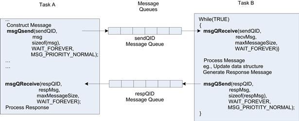
FIGURE 7.14 Message Queues.
Figure 7.14 uses VxWorks API’s calls to demonstrate the example. Two noteworthy arguments are in the calls (in addition to the message-related calls). The first is the blocking behavior: the example in Figure 7.14 blocks the calling thread forever when the task is waiting for a message; that is, the task is placed in the blocked state when no are messages in the queue and transited to ready when messages are in the queue. Similarly, on the msgQSend() call, the sending task may block if the queue is full, and the receive task does not draw down the messages. Balancing task priorities and message queue sizes to ensure that the system does not block or give unusual behavior is a task you will have to perform as an embedded software designer using an RTOS.
Device Driver Models
A function of the operating system is to provide arbitrated shared access to I/O devices in the system. Applications do not directly interact with the I/O devices but instead make use of operating system services to access them.
A number of different device driver models may apply to differing device classes. Some device drivers provide services to other elements with the operating system, while other device drivers provide access to user space applications and the devices are managed directly by the application. A general classification of drivers is as follows:
• Serial port drivers—Many embedded systems provide a UART interface that is connected to a host or debug system through a RS232 serial cable. The UART device driver allows for character reception and transmission of octets to the serial port. The driver supports configuration of the port parameters such as baud rate and flow control. The driver usually presents a /dev/ttyN node, which can be opened using the POSIX open() call. Once the file descriptor is obtained from the open call, calls to read()/write() data from/to the serial port.
• Network device drivers—The device driver interacts with the network interface, such as an Ethernet or Wi-Fi™ interface. The network device driver connects to the TCP/IP stack within the operating system and offers user level services through the BSD sockets API.
• Serial ATA—Most disk drives (both solid state and magnetic hard disk) are attached via serial ATA. The SATA interface defines an advanced host controller interface (AHCI). The driver provides block services to a file system driver. The file system driver provides the file system capability to the operating system.
• Flash—Flash storage is a special class of block driver. The flash driver must manage, erase, and program the flash blocks. The driver must ensure that all blocks of the flash device are used over time, in a process known as wear leveling.
• Bus drivers—In many cases the device being managed is connected to the CPU via a bus such as PCIe™, USB™, or SMBus. Such buses have mechanisms to identify the devices attached to the bus. The bus driver for each bus type scans the bus for devices and allocates the required resources to the device. A PCIe bus driver is described below.
• Interrupt controller—Although the interrupt controller could be considered a device driver, in most operating systems it is an integral part of the operating system and is not generally abstracted for direct user access.
In some cases there are additional device drivers that operate in conjunction with the low-level device driver, such as USB class drivers. The low-level device driver provides services to the class driver. Figure 7.15 shows the high-level relationship between devices, drivers, and services.

FIGURE 7.15 Device Driver Relationships.
As you can see, the hierarchy in Figure 7.15 demonstrates a significant amount of abstraction of the device and allows for the provision of many services across many physical interfaces. Let us consider storage as an example. An application uses traditional C library/POSIX calls to open, close, read, write calls to the selected file descriptor which subsequently operates on a file on the file system. The operating system provides generic service calls to facilitate these C library/POSIX calls. These calls are the contract between the operating system and applications. The file system receives generic service calls, then calls file system–specific calls to read and write files. There are many different file system types, such as File Allocation Table 32 (FAT32), EXT2/3, and Journaling Flash File System 2 (JFFS2). The file system–specific handlers then call a block level device driver interface. The block device driver manages the block device, which could be a SATA drive connected over a SATA interconnect, or the file system could be connected to a USB mass storage class driver managing an external USB drive. In all cases, there is tremendous freedom to evolve each individual capability without changing the application interface. For example, there has been a great deal of innovation and development in the Linux file systems since its inception, each with increasing robustness, performance, and resilience.
In Figure 7.15, we also show a sample flow for a Bluetooth™ device. Bluetooth devices are often connected via a high-speed UART. The UART provides a host controller interface (HCI) where the serial stream is formatted in accordance with the Bluetooth standard HCI definition. The HCI driver connects to the UART driver connected to the device. The Bluetooth stack provides a number of Bluetooth control services and connects to the TCP/IP stack to provide Personal Area Network (PAN) IP services between devices. Again, this example serves to show the tremendous capabilities and innovation that result from achieving the appropriate level of abstraction between subsystems in the operating systems.
As you have seen, there are a number of different device driver models in place. In many cases the driver provides services to other modules within the operating system. Also, the entry to the device driver often provides a reentrant API; this means that the API can be called from multiple contexts and it is the driver’s responsibility to ensure that data structures are protected from concurrent access. The driver typically relies on synchronization principles (such as mutexes) to ensure safe concurrent access to the actual device or data structures associated with the device. To ensure high-performance drivers, it is important to minimize the amount of time the driver is serialized in these critical sections.
A device driver must manage the memory associated with the payload being sent or received from the device. The device driver or the device through DMA must be able to access the payload data being sent or a receive buffer for data being received. There are a number of scenarios that relate to the accessibility of this memory by the driver or device, depending on where the buffer is residing.
In a flat memory system with no process separation, the buffers are always resident in memory. This is the simplest case to handle for the device driver writer. The driver is executing in the same memory context as applications and drivers; as a result the driver can directly read from/write to the buffer. The buffer is resident in DRAM and the device may also use direct memory access (DMA) to and from the buffer. The biggest concern with a flat memory system with no separation is security and robustness of the system. Because any application can read/write data from other applications or device drivers, the application could obtain information or accidently destroy data structures if the application had defects (and of course, all software has some defects).
In operating systems including real-time operating systems that provide separate address space between user process and the kernel, buffers provided to the device driver may be resident in kernel memory. The driver is running in the same process space (kernel) and has direct access to the buffer. The kernel buffer is not subject to paging and will always be accessible until the driver frees the buffer or returns the buffer to an upper layer. You may have considered that if there are defects in the driver and it runs in the context of the kernel, then defects in the kernel can have a significant impact on the robustness and security of the system. This is true—a buggy device driver will likely crash the entire system, and, to make matters worse, such crashes are difficult to debug if the driver has corrupted a kernel data structure. In some operating systems, there is a trend to move device drivers (or portions thereof) to user space to increase the robustness of the system.
In the case of operating systems that support process separation, the device driver may be providing a direct interface to user space applications (such as /dev/tty in Linux). In this case the top layer of the driver is called with a memory descriptor with references to the user space buffer in the call. The driver must perform buffer copies between user mapped buffer and an allocated kernel buffer. The remainder of the driver then operates on the kernel buffer. There are also techniques for mapping the user space buffer to kernel space; more details can be found in the NMAP section in Chapter 10, “Embedded Graphics and Multimedia Acceleration.”
The case where memory buffers are originating from a user space application is an important one, and we will provide more details. A buffer that has been allocated to a user space process is a virtually contiguous buffer. The buffer has a base address and a length, and the length can be very large (as large as the system can allocate to a process depending on system resources). The memory management system (using the MMU) maps the large virtually contiguous buffer to a number of physical pages in memory. The buffer may or may not be physically contiguous. The user space buffer is represented as a list of physical pages. The device driver uses a system call to copy data from the user-mapped virtually contiguous buffer into kernel buffers. The kernel buffers themselves have a maximum contiguous size, although it is best to assume that the maximum contiguous kernel memory you can allocate is one page. In order for the copy to take place, the kernel must provide a kernel virtual mapping to allow the CPU to read the data and allocate a kernel buffer. Given that, the virtually contiguous user space data is copied into a number of kernel buffers. Linux kernel provides functions such as copy_from_user(to_kernel_pointer, from_user_address, size). The function copies size bytes from the user address to the kernel address pointer. The function actually executes in the context of the user space process, in that the page table mappings for the user space pointer are valid.
Some operating systems (BSD and VxWorks) have optimized the exchange of network buffers through the provision of zero-copy memory buffers. In this case the application writes directly into the network buffer structure and can submit the packet to the stack without a copy operation.
Given that data elements within the kernel are composed of a list of physical pages, the operating systems often defines a construct for a scatter gather list. A scatter gather list is a mechanism defined and supported by an operating system to represent a list of data that is not physically contiguous. The scatter gather list is operating system–specific, and when available it should be used to pass data elements that are larger than the contiguous elements in the system (usually a page). The Linux kernel makes extensive use of scatter gather lists and defines structures and management functions in /linux/include/scatterlist.h. The TCP/IP stack incorporates a scatter gather list representation into the stack buffer known as an SKBUFF. The device driver must iterate through the scatter gather list and write to the devices’ data registers or create device descriptors that point to the scatter gather list as it is submitted to the hardware. The scatter gather list is usually represented as an array of pointers to data elements, or alternately the scatter list can be represented as a linked list structure. The best structure depends on the access pattern of the driver/stack. The array-based approach is best if the CPU needs access to an element down the list (for example, the third buffer is the start of the IP packet in a packet list). However, since the maximum array size is often fixed, the linked list approach can support a very long list of buffers, but the list traversal can take some time. Figure 7.16 shows examples of both array-based and linked-list–based scatter gather lists and a combination structure used in Linux. The data payload pointed to by the data pointer should be viewed as logically contiguous data but is likely to be physically discontiguous.
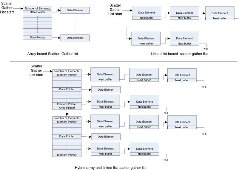
FIGURE 7.16 Scatter Gather Structures.
The Linux scatter gather list is a combination of both an array and linked list. The determination of which format will actually be used is made at runtime by the design of the software using the scatter gather list.
Low-Level Data Path
There are two distinct aspects of the data path for most device drivers. At the lowest level, the device driver directly interacts with the registers and descriptors associated with the device. At the higher level, the device driver presents an interface to the operating system or to the applications.
The device driver is called with data to submit to the device; this is often called the transmit or device send call. The transmit function contains a pointer to the data to be transmitted. The data structure containing the data is directly accessible by the driver code; that is, the driver can access the data in the transmit call. The interaction model is dictated by the presence or absence of DMA capability in the device. For the simplest case, the device contains a memory-mapped first in, first out (FIFO) register. Data written to the register will be transmitted on the device interface. The device provides indications when the FIFO is full. When the FIFO is full, the device driver must not write to the FIFO and wait for the device to drain the FIFO. In the context of the transmit function, if data remain to be transmitted, the device driver may poll the device status register until the FIFO has room, at which point the driver writes data to the FIFO. If the driver send function does not return until all the data have been written to the FIFO, it is considered to be a blocking call. Return from the driver indicates all data have been sent to the FIFO. In some cases, the driver may also wish to ensure that the data have actually been drained from the FIFO and transmitted (for example, a flush). In this case the driver call blocks until the FIFO indicates that it is empty. Blocking calls such as the one described are often used during the early part of a boot phase; polling the device is not a recommended design when the operating system is up and running with interrupt support. Most devices can be configured to generate interrupts when different state changes occur in the FIFO. The common interrupt triggers would be transitions to Full, Empty, Nearly Full, and Nearly Empty, to avoid polling and support a nonblocking interaction with the device. Consider a call where we are asked to transmit 1 kb of data, with a FIFO depth of 32 bytes. The device driver first fills the FIFO until the FIFO is full (as indicated by the FIFO status). The transmit function then places the transmit data buffer into a deferral queue, with an indication of how much data remain to be transmitted. The device is configured to generate interrupts when the FIFO transitions to nearly empty (for example, the FIFO contains 8 bytes to be transmitted). The device interrupt handler inspects the interrupt status register and identifies that the device’s Nearly Empty FIFO interrupt event is active. The interrupt handler consumes the buffer from the deferred transmit queue and writes data to the FIFO until it is full again. The buffer is then returned to the deferred transmit queue. These steps continues until all the data has been consumed from the buffer. At this point the buffer must be returned to the pool from which it was allocated, typically by calling a transmit complete callback with the buffer. As the transit call is now asynchronous, there may be additional transmit calls while the driver is still processing previous submissions. In this case, all the data requests are added to the tail of the deferred transmit queue. Using a Nearly Empty FIFO interrupt instead of a FIFO Empty interrupt improves the likelihood that the device will transmit data continuously, if the nearly empty threshold is configured to allow sufficient time for the CPU to be interrupted and to refill the FIFO before the FIFO goes empty. This can often be a critical factor depending on the device usage model. Figure 7.17 shows the interactions between the different elements described above.
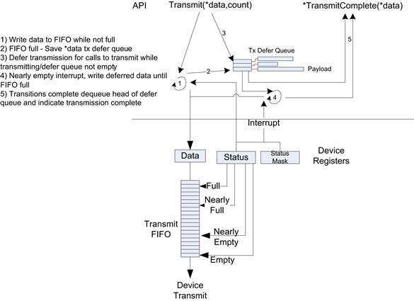
FIGURE 7.17 Low-Level Transmit Driver Path.
In the case of the receive path, two patterns are frequently used; the first is driver polling and the second is to use interrupts to indicate when data is received (in some cases a hybrid of the two is used—see NAPI below).
In a device poll receive call, a receive function is called with a pointer to a buffer where the receive data is to be placed. The device status register is read to assess if there is any receive data available in the receive FIFO. If the status register indicates that the FIFO is not empty, then the device driver can read data from the receive FIFO and place it in the receive buffer. The receive function continues in a loop until the receive buffer is full or no more data are in the FIFO, at which point the polled receive function returns with an indication of how much data has been placed in the receive buffer. More likely, a device driver will be interrupt driven. In this case, a receive buffer must be provided to the low-level driver prior to the reception of data. When a buffer is provided, the device receive interrupts are enabled. For example, the device could be configured to generate an interrupt when the FIFO status transitions from Empty to Not Empty. The interrupt hander reads the receive FIFO until the FIFO is empty or the buffer provided is full. Once this occurs, the interrupt handler calls a receive callback function (previously registered function pointer) with a pointer to the buffer just populated with receive data. Figure 7.18 shows the sequence just described.
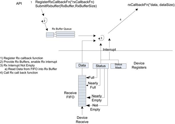
FIGURE 7.18 Low-Level Receive Data Path.
Direct Memory Access
The low-level data path described above assumed that the CPU wrote to and read from the data registers on the device. This is generally a poor use of the CPU, and the CPU utilization associated with device input/output increases substantially as the device interface speed increases. A device driver design that is reasonable to handle a low-speed UART (for example, 38,400 baud) is no longer viable at higher speeds (such as 4MBits). A more efficient design is to allow the device to read and write buffers directly in system memory. A device with the capability to directly read and write system memory is said to be Direct Memory Accessible (DMA) capable. Practically all modern I/O devices make use of DMA to read and write system memory. In this case the CPU writes the system physical address of the data to be transmitted or the physical address of a receive buffer into registers within the device. Instead of the CPU moving the data to and from the FIFO to memory, the device automatically moves the data and then provides an indication that the data transfer is complete—primarily through the generation of a transmit complete interrupt or a receive data interrupt.
The use of DMA for data payload is far more efficient than using the CPU to move data, but the CPU still interacts with the device writing buffers to the hardware transmit FIFO and writing receive buffer pointers to the receive FIFO hardware. Interacting directly with hardware device registers is typically a slower operation than reading or writing to system memory, so an extension of the technique above is to create transmit descriptor rings and receive descriptor rings in system memory and only read or write head/tail pointers when necessary. In most cases this reduces the level of direct CPU-to-device interaction, and system memory is used as an intermediary. The descriptors can be extended to provide commands to the transmit function or provide status information for data received. Figure 7.19 shows the memory structure and example contents for a transmit descriptor ring. Logically, the CPU is a producer of transmit data on the ring, and the device is a consumer of data from the descriptor ring. The device maintains the head pointer to indicate the current transmit buffer, and the CPU must write to the tail pointer when the CPU has updated the transmit descriptors in memory. The CPU may update multiple descriptors for each tail pointer update, and this greatly improves the efficiently of the device driver.
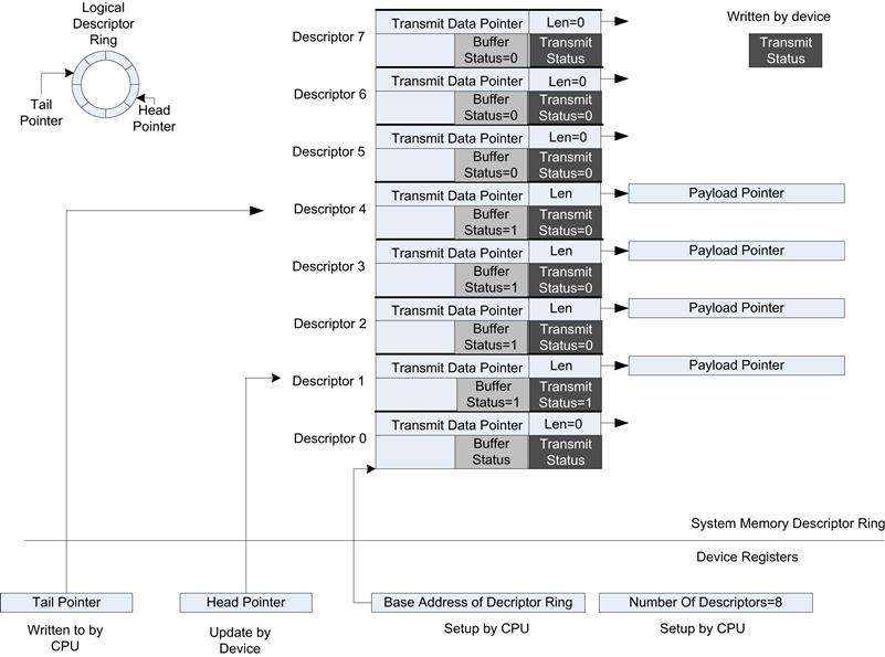
FIGURE 7.19 Example of a Transmit Descriptor Ring.
The following is a sample sequence of events to transmit data using a transmit descriptor ring.
1. The first step is to initialize the hardware registers with the base address in system memory of the descriptor ring, along with the number of descriptors. The device uses the number of descriptors to allow the hardware to automatically wrap around the head pointer.
2. For each payload to be transmitted, the driver must write to the transmit descriptor. The driver updates the payload data pointer, data length, and sets the data valid bit.
3. After one or more descriptors have been updated, the tail pointer must be updated in the device. This is carried out by writing the device tail pointer register. This write event triggers the hardware device to read (via DMA to system memory) the descriptors between the head of the ring and newly updated tail of the ring. For each valid descriptor (with buffer status = 1) the device will read the data pointed to by the transmit descriptor and transmit the specified (len) number of bytes on the interface.
4. For each descriptor consumed, the device updates the descriptor in system memory to indicate that the device has consumed the data and transmitted it on the interface. The internal device head pointer also moves to the next descriptor to be consumed.
Figure 7.19 shows a snapshot in time for the head, tail pointers, and descriptor status.
Memory Addresses
When a device supports DMA, the address in the descriptors and registers must be populated with an address from the perspective of the device. There are three separate address types in an embedded system that supports DMA.
• CPU virtual address—This is the address of the buffer mapped to the current process space, usually that of the kernel. The device driver can read or write to these addresses.
• Physical address—This is the physical address in memory that corresponds to the virtual address. The MMU translates the CPU virtual address to the physical memory address when the CPU preforms a read or write.
• Bus address—This is the address generated by a device as DMA agent targeted at system memory.
The MMU translates between virtual and physical address (for CPU originated transactions) and the bus may convert between bus address and physical addresses (for device originated addresses). The device driver must convert any address that it writes to the device into a bus address. For example, consider the address of the base of the descriptor to be virt_base_addr, then the driver must use system functions to convert to an appropriate address, for example:
bus_addrs = phy_to_bus(cpu_virt_to_phy(virt_base_addr))
In many cases the physical addresses are mapped 1:1 to bus addresses, as is the case for PCIe buses on Intel platforms, but it is never a good idea to assume this. OS-provided conversion functions should always be used.
Given the frequency that device drivers may perform a virtual-to-physical-address translation for data payload, the system is often configured to have a simple mapping between the virtual and physical address for kernel space. This could be either a 1:1 mapping or, as in the case of Linux, a fixed offset between the two. Having a simple translation between the virtual address space and physical address space for the kernel makes conversion very efficient.
BUS Drivers
As you have seen in Chapter 4, there are a number of bus standards such as PCIe, USB, SMBus, and I2C. PCIe, USB, and SMBus all provide a mechanism to scan the bus at runtime and identify what devices are attached to the bus. This process is known as enumeration. The bus driver handles the enumeration of the bus and provides services to each of the devices that are attached to the bus. Each bus driver has its own pattern for supporting the attached devices. For example, a PCI bus driver performs the following steps:
• Scans the PCI configuration space for devices.
• Saves the device ID—a uniquely assigned number of the device manufacturer and specific device.
• Identifies the memory size requested by each of the base address registers (configurable chip selects) and allocates the memory space for the device.
Once the scan is complete, the drive initializes a device driver registered for the specific device ID. In the case of Linux the devices are probed and the pci_dev structure is provided, such as in the example below:
static int __devinit device_probe(struct pci_dev ∗pdev,
const struct pci_device_id ∗ent);
The pci_dev structure provides many elements, but in the context of this discussion, the resources and irq entries are pertinent. The resources elements is a list of memory address assigned to the device. The irq is the interrupt vector assigned to the device (this may be shared/unique).
The bus driver provides an abstraction that allows the device to be written generically regardless of the resources allocated to the device. It allows the driver to be unaltered for devices that are actually incorporated into an SOC or on an external PCI bus.
Networking
Most operating systems provide a networking stack of some kind. The most prevalent networking stack deployed is an Internet Protocol (IP) stack. The IP stack provides an application library to open/close connections to remote devices and send and receive data between the remote device. The application API is provided by a sockets library (usually BSD sockets). The APIs are consistent across nearly all platforms that provide an IP stack. Chapter 12, “Network Connectivity,” provides more detail on networking.
The TCP/IP stack takes socket send and receive requests from the applications. The application may select either Transmission Control Protocol (TCP) or User Datagram Protocol (UDP). The protocol definitions are defined and maintained, along with many other networking protocol standards, by the Internet Engineering Task Force (IEFT). The protocols are identified by the RFC number. The original UDP RFC is RFC768, published in 1980.
TCP is a reliable streaming protocol with retransmission of data if it is lost across the network. UDP is an unreliable datagram protocol. The TCP/IP stack performs the required protocol level processing for the protocol type.
Aside
In embedded systems the UDP protocol is often used within systems to send messages between cards (within a single chassis). The application messages directly are mapped 1:1 to the datagram being transmitted. However, in many cases we would like to use a reliable datagram service; the Stream Control Transmission Protocol (IEFT RCF 3286) provides reliable ordered delivery of datagrams.
For outgoing packets the IP layer adds the IP header to the PDU and selects the appropriate network interface to submit the packet to. The outgoing network interface is identified by looking up the routing tables and the destination IP address for the packet. In some cases the PDU is also fragmented to PDUs that are no bigger than the Path Maximum Transmission Unit (PMTU). The PMTU is the minimum MTU of any link between the source and destination. The MTU is the maximum size in octets/bytes that a layer can forward. For example, the MTU on an Ethernet (802.3) interface is 1492 bytes (RFC 1191). Fragmentation is an expensive operation (particularly for the receive-side processing), and it is best to ensure that upper layers do not generate PDUs that require IP fragmentation.
For packets received from the network interface, the IP layer validates the header, identifies the appropriate protocol handler, and forwards the packet to the appropriate protocol hander (TCP/UPD/ICMP/other). The IP layer must reassemble any fragmented packets that arrive.
At the bottom of the stack are the network device drivers. The driver model used for networking interfaces is usually different from the generic OPEN/CLOSE/IOCTL driver model described above. The network driver interacts with the protocol stack directly and does not generally provide any direct device interface. A network device driver is specific to the type of network interface (such as Ethernet or 802.11), the driver mode of the OS, and the network stack (such as IP). Figure 7.20 shows an overview of the stack and network interface drivers.
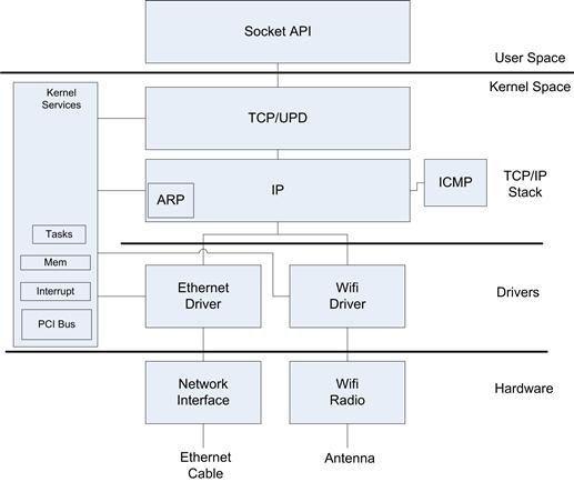
FIGURE 7.20 Network Stack and Device Drivers.
The following APIs are generally provided by a network driver:
• Load/Unload—These are services to load a dynamic driver. In many cases device driver loading is deferred until the hardware presence is established by a discovery process such as PCIe enumeration. In many cases, the network interfaces (LAN/wireless LAN) are separate devices connected to the SOC (via PCIe or USB) which makes dynamic loading useful.
• Send/Packet Transmit—This is a function that takes a buffer in the network stack format to be transmitted to on the network interface. The function typically populates a transmit descriptor in the network interface with a pointer to the buffer provided in the packet transmit call. The network interface sends the packet via DMA from the buffer at some point later. The transmit call does not wait for the packet to be transmitted and returns immediately.
• IOCTL—I/O control interface is a generic control API for the driver. The IOCTL functions control behavior of the MAC such as setting the MAC address of the interface and getting device statistics such as packets transmitted/received.
• Device Stop/Start—These functions are used to enable or disable the device. When a device is stopped, no packets are transmitted or received. This capability is usually controlled by user space programs to bring the interface up or down.
On arrival of a packet on the network interface, the network device sends the packet via DMA into a receive buffer and interrupts the processor to indicate that a packet has arrived. The network driver then sends an event or notification to a deferred work task. When the deferred task wakes up to process the packet arrival event, it makes a call to submit the packet to the IP stack. The Linux kernel calls
netif_rx(struct sk_buff ∗skb)
netif_receive_skb (struct sk_buff ∗skb)
are used to send a packet from the driver up into the TCP/IP network stack. The function takes a pointer to an sk_buff buffer. An sk_buff buffer is a special buffer format used to carry packet data up and down the TCP/IP stack.
Buffer Management
Once the network interface has completed transmission of a packet, the network device generates an interrupt to indicate that the packet has been transmitted. The network device driver reads the transmit complete descriptor where a pointer to the buffer that was transmitted can be obtained. The driver usually frees the buffer back into a buffer pool. Similarly, in order to ensure that a buffer is available for receive packets, the device driver must populate the network interface receive buffer descriptors with buffers allocated from a buffer pool.
Some embedded systems have extensions to the socket APIs. For example, the socket library provided by FreeBSD and VxWorks provides an option to send and receive data from a user buffer without having to copy it into a kernel network buffer. This is known as a zero copy socket option, and it can improve performance for some embedded networking applications.
Polling Interface
In many cases, the network interface driver provides a mechanism to poll the network interface for received packets. The network stack may be set up to poll for network packets for two reasons. The first is to improve the overall performance of the device driver under varying packet arrival rates. When a low rate of packets arrives at the network interface, it is best for the network device driver to interrupt the processor when each packet arrives; in this case there is little delay in processing the packet that has arrived. If the network load is high and a burst of packets arrives with the minimum interpacket arrival time, it is often better to be interrupted on the arrival of the first packet and then to poll the interface a number of times before the packet related interrupts are re-enabled from the device. This has the effect of reducing the total number of interrupts processed for the bursty traffic. In some cases where the network traffic is at a sustained high rate, a scenario known as live lock can occur. Live lock in this case is when the CPU is spending all of the time servicing network receive interrupts but never has an opportunity to process the packets. The Linux stack implements a concept known as New API (NAPI) (http://www.linuxfoundation.org/collaborate/workgroups/networking/napi) to switch between interrupt driven operation and polled operation based on the network load. There are also interrupt moderation schemes developed for some network interfaces to help moderate the interrupt rate using inter packet timers and network traffic load.
The other reason to provide a network polling API implementation is to allow the network interface to be used as a debug interface when debugging the operating system. For example, you can connect to the Linux target system and use the GDB debugger to debug the kernel from a host machine across an Ethernet interface that supports the polling. Network interfaces that only operate with interrupts cannot be used for this purpose, as interrupts processing is prevented when a breakpoint is hit in the kernel.
Acceleration
In many modern network interfaces, the networking device can offload some of the work normally carried out by the IP stack. The simplest is TCP receive checksum offload. In this case the checksum for TCP/UDP checksum is validated by the network interface card. The network device descriptor indicates if the checksum is okay, in which case the driver indicates that the checksum need not be checked by setting a flag in the network packet buffer. With Linux the Sk_buff- >ip_summed flag is set to CHECKSUM_UNNCESSARY. Setting flags in Sk_buff is a common design pattern used in the network drivers to either defer work to the NIC for packets to be transmitted, or to indicate preprocessing/checking carried out on received packets.
Storage File Systems
File systems are predominantly used to provide an abstract mechanism to open and close or read and write to a storage device. The storage device may or may not be persistent. Many different file systems are implemented in modern operating systems, with a subset available for real-time operating systems. In a traditional desktop system such as Linux or Microsoft Windows, the operating system provides a mass storage file system that is applicable to a large mass storage device such as a magnetic hard disk or solid state drives. Windows provides the New Technology File System (NTFS) and FAT file system. Linux desktop distributions predominantly use EXT3/4 file systems at the time of writing. In embedded systems, there are many more, such as JFFS2, TFAT, CRAMFS, RAMFS, and INITFS (all of which we will describe later).
Note
The file system abstraction is also used to provide a logical namespace used to access device resources in kernel. Consider the Linux /dev/,/proc, and /sys pseudo file systems, which are mechanisms used to provide input/output and obtain information from the kernel and control functions within the kernel.
When an application performs a write to the file system, the file system must allocate blocks on the storage device and write the required contents into the blocks allocated on the storage device. This operation is typically an asynchronous operation from the perspective of the applications. The write call returns immediately (does not block the application) even though the data may not have been written to the device. The file system drivers will at some point reflect the write in the file system. There are many reasons to defer the actual writing, the primary one being performance. A sophisticated file system will consolidate file system requests from a number of applications concurrently, and it schedules (order) the requests with the purpose of maximizing the file system throughput. At the time of writing, there are four I/O scheduler options available (in Linux):
Given that updates to the file system occur asynchronously to the application, there are cases where the contents on the mass storage do not reflect the current logical state of the file system. At any point in time portions of the data being written to mass storage may still reside in CPU memory buffers or even in buffers within the storage device (in the drive itself). In cases where the storage media is going to be removed or the system is about to be restarted, it is critical to issue a synchronization request to the file system prior to such an event. The synchronization request flushes the data all the way out to the storage media, and the media is guaranteed to be consistent when the media is reinserted or the system restarts. I’m sure you have used the Windows option to “stop a USB device” prior to removal; this effectively ensures that any data contents still on memory are written out to the pen drive. I’m equally sure that you have at times simply removed the drive without taking the time to issue the request—and it has probably always worked, but there is a chance that the data are corrupted or, worse, the file system management structures are not consistent. In embedded systems, this could prevent a system from booting properly or an application getting incorrect data and failing to operate correctly, so it is particularly important to synchronize the file systems before shutdown, restarting, or media removal.
Two distinct file system types are in use today, journaling and non-journaling. A journaling file system maintains a record of updates or deltas to the existing state of the mass storage device. The updates, primarily to metadata, are carried out as transactions. Each transaction is an atomic operation to the file system, thus at any point the file system can be recovered to a consistent state. The journal updates are held on the storage device. When the file system is mounted the journal entries are applied to the file system baseline. This also occurs periodically during the operation of the file system. File systems with journaling capability such as EXT3 rely on a Journaling Block Device driver to provide transaction-based journaling capabilities to the underlying block devices.
A non-journaling file system such as the File Allocation Table 32 (FAT32), often used on USB pen drives, performs all updates directly to the file system management structures (such as file allocation tables). A journaling file system is more resilient to un-notified removal of device or power. The underlying structures are always consistent, and the worst case is loss of some transactions.
We should distinguish between file system consistency and ensuring that the contents of a file reflect all up-to-date application transactions. The journaling file system is very resilient and ensures consistency. However, it may lose the latest transactions depending on the scenario. In this case the application data may not have actually been made persistent on the device. There are transaction-based file systems in which the application writes a transaction that will be written as an atomic operation to the file system. The transaction will either complete in its entirety or none of the transaction will complete (if an error occurred). It allows the application to ensure data consistency by making sure the transactions are written atomically. The application can also ensure that the transaction has made its way to the mass storage device. Transaction file systems are EXT3, JFFS2, and YAFFS2.
In many embedded systems, flash-based file systems are required as the mass storage devices use flash memory. We mentioned in Chapter 4 two primary types of flash, NAND and NOR. There is still a preponderance of NOR-based flash where storage requirements are modest and reliability is paramount (many microcontrollers actually include on-die flash, and in such cases, it is generally NOR). There are two classes of file systems commonly used. The first is read-only compressed file systems, such as CRAMFS. CRAMFS is a simple file system that uses zlib compression routines to compress each file page by page. The file system can be accessed using normal file access routines, and random access is supported. A CRAMFS file system could be used to hold the root file system of an embedded system.
An alternative approach to providing the initial file system for a Linux kernel boot is to use INITRAMFS. This file system consists of an archive that is stored on the flash devices. The archive contains a gzipped cpio format image. This initial image is decompressed at startup to create a root file system (ROOTFS). The root file system is read-only, as any updates will not be written to the compressed archive. This root file system is ramfs. A ramfs file system is a RAM-resident file system with no backing store. It actually reuses much of the kernel’s disk caching mechanisms.
Another file system to consider is a journaling flash file system such as Journaling Flash File System (JFFS2) or Yet Another Flash File System (YAFFS2). JFFS2 file systems operate by continuously writing to the “end” of the file system for wear-leveling purposes and as such is, strictly speaking, a log-structured file system. As the name of the first of these file systems suggests, these are file systems that support flash devices and use journaling. These flash file systems support both NAND and NOR devices. YAFFS2 provides the following features (http://www.yaffs.net/):
• NOR and NAND device support (although it appears to have been primarily designed for NAND devices)
To support flash file systems, a flash block driver is provided; this is a low-level interface that manages the blocks on the device. On a Linux system these are provided by MTD drivers.
Device Wear and Tear
In many embedded cases, the device will be operational for many, many years, having a life expectancy of perhaps greater than 10 years, depending on the application. In such cases, you should be cognizant of the file system activity and the resultant use of either magnetic-based media or flash devices. Where possible, the system should avoid frequent access to the mass storage device and alternatively either rely on RAM-based file systems or ensure that the applications only write to the storage devices periodically. Even with techniques such as wear leveling for solid state devices, they still have a finite number of cycles supported. If you have a device that supports 100 million cycles but performs a write every second, the device may fail in a little over three years.
Power Interactions
In embedded systems, many systems have a number of different voltages required for the platform. There are two scenarios that are important to comprehend in the design of the embedded system, both of which can have consequences to the robustness of the file system. The first is un-notified power removal. As we mentioned above, the file system or application data may not be consistent when the system restarts depending on the file system selected and what operations were being performed on that file system. In cases where resilience is absolutely required, the best approach is to avoid situations in which power can be removed from the CPU and storage device without notification. This is often accomplished by having a large capacitor and a circuit to sense the removal of the main voltage. The removal of the main supply triggers an interrupt (highest priority) to the processor. The CPU can then take the necessary operations to flush the file system data. The time available for such operations is typically very brief, as a capacitor, however large, would provide only a tiny time margin to sync the file system. In many cases, only critical file systems for platform boot are safeguarded using this mechanism. The other challenge in embedded systems is a topic known as brownout. Brownout occurs when the voltage level drops but is not completely removed. Since many systems require a number of different voltages in the system, the reduction in input voltages may cause each of the derived voltages to go out of specifications (although not all voltages go out of specification). This can cause file system consistency issues, if, for example, the flash voltage drops out but the CPU does not, or vice versa.
Figure 7.21 shows a brownout voltage diagram. It is important to validate and test your embedded system with both removal of power and brownouts while performing a significant number of file system transactions.

FIGURE 7.21 Brownout Events.
Power Management
An ever-increasing responsibility of the operating system is to effectively manage power on the platform. Chapter 9, “Power Optimization,” describes some of the overall principles in managing power. Although a number of techniques apply to changing the dynamic power of the system through changing the frequency and core voltage of the CPU, in many embedded cases, the designer is likely not willing to design a sufficient margin for the variable performance when the system is active. It is more likely that the system is designed to perform at a fixed high-performance point and to aggressively bring the system to a sleep state when there is no work to be done. In the case of the operating systems, this is usually determined by the behavior of the “idle” function. This is a function that is scheduled when there is no other high-priority work to be done. The thread may simply halt the CPU. A halt instruction typically puts the processor in a lower power state while waiting for the CPU to receive an interrupt and continue execution. In modern Intel architecture systems, the idle function uses the MWAIT instruction. The MWAIT instruction takes a CPU/platform-specific hint to the targeted sleep state of the CPU. An embedded system designer should be aware of exit latencies associated with CPU sleep states; in general, the deeper the sleep state, the longer the latency to wake up. The operating system may provide configuration of these capabilities. An example of dynamically controlling the suggested sleep state of the CPU can be found in the Linux IA-32 idle driver.
Many desktop-based operating systems support a formal transition to a suspended state, where all state information is saved into DRAM (self-refreshed) and all other aspects of the system are powered down: CPU, caches, and all devices not requiring monitoring for a wakeup event. This state is known as S3 on Intel platforms. When the wakeup event occurs, the operating system resumes execution and sends a notification event to each driver to reprogram the devices. Such a capability is rarely used in embedded systems where they are expected to perform the application function at all times. A further extension of the suspend to RAM (S3) operating system state is hibernation. Hibernation is similar in principal to S3 except that the contents of DRAM are saved into a hibernation file on a mass storage device. Once this is complete, power can be totally removed from the system (except for any wakeup devices, such as support for wake-on-LAN from the NIC card).
Device drivers also play a part in the power management of the system. Each device driver may be asked to place a device in a particular power state; the driver must perform the action and respond to the kernel when the task is complete.
In addition to the basic technique of controlling the idle function of the file operating system, some platforms actively manage the device’s state (power and clock) depending on the current usage of the device. This is an active topic in embedded and especially mobile systems. However, few standardized approaches allow the operating system to automatically manage the overall system at this level of detail (at the time of writing).
Real Time
The real-time behavior of an operating system is critical in many embedded platforms. The real-time behavior is usually defined by having a deterministic bounded time from an external event such as an interrupting device to the execution of the real-time handler (task or thread) and the action resulting from the original event. This may be an output or simply data analysis of the incoming data. Figure 7.22 shows the flow from hardware event to task.
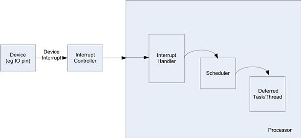
FIGURE 7.22 Interrupt Delivery to Thread Flow.
Many system aspects contribute to the latency from interrupt event to the execution of the thread to handle the interrupt.
Device Interrupt Delivery
In modern embedded systems the delivery of interrupts to the CPU is not likely to simply consist of wires with the SOC or platform. The interrupts are likely to follow an internal path and coexist with other memory-targeted traffic from the device generating the interrupt. This is particularly the case when devices are presented as logical PCI devices within the SOC. Given that the interrupt traffic is mixed with traffic from other devices, there may be congestion in the path. This can lead to increased jitter and non-determinism in the interrupt delivery. This can be alleviated by ensuring that traffic from devices that a require real-time response is allocated a prioritized channel through the fabric. This is usually controlled by registers assigned to the device.
In some designs, the interrupts are wired directly from the device to the interrupt controller. In this case there is no opportunity for delays in the I/O fabric. In many cases a device that has generated an interrupt has also generated memory write transactions (for example, DMA of data from the device into memory). If the SOC device hardwires the interrupts, the processor may start to handle the interrupt before the memory has actually been updated (for example, when the memory write transaction has been delayed in the fabric). In this case, you should perform a device read; the data returned from the read will stall the processor until the previous data writes from the device have been pushed through the I/O fabric. The net result is that both wired or message-based interrupts have similar behavior if the interrupt handler needs to wait for system memory to be updated.
An additional consideration for an SOC design is the requirement to support multiple processors. In this case interrupt message-based interrupts are easily extended to steer interrupts to a specific core.
Processor Interrupt Handler
The processor only starts to process an interrupt on an instruction boundary; on most platforms instructions have variable execution delays and can add to the jitter associated with the transition to the first instruction of the interrupt handler. Once the interrupt has been delivered to the processor, the processor has to be in a state where the interrupt can be processed. The processor may have the interrupts disabled or processing an interrupt. If the interrupts are disabled, then all interrupts are blocked until the processor re-enables interrupts.
When the processor is processing the interrupt, the processor is generally not re-interruptible. The interrupts can be re-enabled to allow higher-priority interrupts to interrupt the processor.
Once the processor has accepted the interrupt, the processor transfers control to the vector associated with the interrupt. This is known as the interrupt handler. The interrupt handler may require the memory management unit to fetch translations via page walking, which can add to the delay/jitter in executing the interrupt handler.
The interrupt handler should perform the minimal processing possible and defer as much of the device processing to some form of deferred task. There are many reasons for this, the first is that it allows the system to re-enable interrupts and accept a higher priority interrupt if one is pending; as we mentioned, in most cases the system is not re-interruptible while in an interrupt handler. The handler in most cases should simply acknowledge the interrupt and send an event to trigger the differed task.
The interrupt handler runs in a very limited context and can access only a small subset of the kernel calls.
In the case of VxWorks, the equivalent interrupt handler might post an event to a message queue, release a semaphore, or send an event to a waiting task. The task would typically be a higher priority and start executing as soon as the scheduler has an opportunity to do so.
Deferred Task
The operating system maintains the processor exception table and calls the registered device driver interrupt handler when an interrupt is to be processed. Once the interrupt handler signals to a deferred work task and returns to the operating system exception handler, the operating system has an opportunity to save the state of the interrupt task to its task control block and schedule the highest-priority ready task. If the priority of the deferred task is high enough, then the operating system scheduler will schedule the execution of the deferred interrupt task immediately.
Figure 7.23 shows the simplest Linux interrupt handler, which simply triggers the execution of a deferred function to perform the subsequent processing for the device.
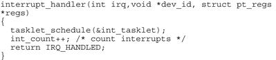
FIGURE 7.23 Interrupt Handler.
In an RTOS such as VxWorks, the deferred task can be any system task. The task is responsible for servicing the device. Linux has a number of specific capabilities that are introduced to provide a deferred interrupt processing interrupt context. This is known as a tasklet. The tasklet is a software interrupt context and it is scheduled by the operating system (once requested by the interrupt handler). Each specific tasklet is guaranteed not to run in parallel even on an SMP system. The system can continue process interrupts while executing a tasklet.
RTOS Characteristics
A real-time operating system or a general-purpose operating system with real-time extensions has design attributes to improve the determinism for each of the phases above. The key aspects that make an RTOS real-time are twofold; the first is to ensure that the processor can accept an interrupt for the vast majority of time, that is, there is almost no time where the operating system cannot accept an interrupt. The second is to ensure very low cycle time for the scheduler to schedule any deferred workload. This requires that the scheduler be very efficient. A dedicated RTOS such as VxWorks or Nucleus is designed from the ground up to ensure such behavior.
In many cases designers wish to make use of a general-purpose Linux and extend it to provide real-time behavior. The behavior extends the scheduler to allow the creation and scheduling of real-time user space threads. The capabilities allow for millisecond scheduling of real-time threads, which is acceptable for many applications.
In many embedded systems an executive is run underneath the full-featured operating system. Xenomai (http://www.xenoami.org) is such an implementation and is described below.
Real-Time Adjuncts
Xenoamai is a real-time framework for Linux. It is based on an abstract real-time operating system core. The core provides a basic set of generic interfaces. This core RTOS is skinned with an API personality that matches many preexisting commonly used interface such as POSIX. Applications written using the traditional POSIX calls under user space Linux can be migrated to the POSIX APIs provided by a POSIX skinned Xenoamai and run as a special higher-priority thread in the context of Xenoamai.
A Xenoamai-based system runs two kernels on the system. The Xenoamai real-time kernel schedules its real-time threads using the Xenoamai scheduler. When no real-time threads are ready to run in the Xenoamai kernel, then the traditional Linux kernel run.
In order for the Xenoamai kernel to ensure deterministic real-time response to interrupts, Xenoamai requires special support by the kernel. The kernel does not support this option by default and must be patched. The patch is known as the Interrupt pipe (I-pipe) patch.
A number of products also provide real-time behavior to Microsoft Windows. These products generally take ownership of the interrupts in the system and provide an environment where application code can execute directly as a consequence of the interrupt trigger.
Licensing
It might seem strange to include a section on licensing in an operating system chapter, but we think a brief discussion is warranted, especially in the context of embedded systems.
In many systems, you may elect to purchase software to be included in your product. This could range from the operating system itself to special-purpose libraries or applications themselves. Such software is delivered under a license. The license dictates how the software may be used and or redistributed. Let’s discuss proprietary and open source licenses.
If you purchase software for inclusion in your product, it may be provided in either binary or source form. Regardless of the form in which you received the software, it will have an accompanying license that specifies what you can do with it. The most common is that you can include it in your product but you cannot redistribute the source code. Depending on how you purchased the software, you may have made a single buyout payment where you do not have to pay for each individual instance you ship as part of your product, or you may have to make a royalty payment for each copy shipped as part of your product. It will be important for you to have processes in your software development to ensure you track the use of such software. These licenses are known as proprietary licenses and each one is different.
Another class of libraries is known as open source licenses. Many such licenses exist but the most prevalent are BSD License, Apache License, and Gnu Public Licenses (GPLv2, LGPLv2, and GPLv3). The BSD and Apache License generally allow you to reuse the code in your own system and do not make any redistribution demands on you, the user of the code. You may be required to mention the fact that you have included the software in your product. If you make changes or updates to such software you are not required to share these changes with an external party.
Gnu Public License 2 (GPL2) is a license that you can include in your product but with the requirement that you mention that you have incorporated the code in your product, and should you make any change to the source, you are also required to provide that source code to anybody who requests it. This requirement is triggered when you deliver the software or product including the code to a third party. Depending on how you link any GPL software into your product, you may also be required to redistribute the source code of your own software. In general, if you are linking to any GPL software you should pay particular attention. There is also a license known as LGPL, which is the same as GPL in the requirement to redistribute any changes you make to the GPL code in source form, but you are not required to redistribute your software if you simply link to the LGPL code. The attribute where linking GPL code to other code triggers the requirement to also release the source code of your code is known as viral license. You should also consider the implications to the entire system. Perhaps you have purchased a software library under a proprietary license. You then download a piece of open source code released under GPL license. If you link the entire software together into a monolithic application (which would not be unusual in embedded systems), then you may have triggered the requirement to publish the source code of the proprietary software—clearly, you probably don’t have such rights.
This is an important area. You don’t want to find that you have an issue blocking the shipment of your product just when you want to release it.
This is just an overview—don’t consider it to be legal advice on this topic. You should make sure you comprehend your company’s interpretation of each software license that applies to your software and external software you plan on incorporating into the system.