Chapter 16
Example Designs
At the risk of this chapter being perishable and out of date before you read it, we felt that at least one chapter in the book should go into a specific embedded design using a specific processor. For this purpose, the Intel® Atom™ Processor E6XX Series SOCs are used, with platform expansion through an interface device known as a platform controller hub.
As an embedded systems programmer, you should be able to read schematics for the platform you are operating on. You probably don’t need to understand the detailed clocking or power control aspects of the design, but at a minimum you must understand the platform at a block level: which interfaces are used to connect devices, which GPIO pin is connected to the LED, and so on. It’s always preferable to be able to refer to the schematics rather than high-level documents describing the platform; these can contain errors, and reading schematics is like looking at source code—it’s unlikely that it does not represent what you are looking at in reality (ignoring any post-fabrication changes). In this chapter we outline the high-level feature sets of a number of components in the system. The intent is to call out capabilities that you as an embedded system programmer should be cognizant of. In many design cases you will be expected to understand the subtleties in the capabilities of a device, not just the first-order data sheet bullet list.
Intel Atom E6XX Series Platforms
The Intel Atom–based E6XX Series processors come in a number of SKUs. This is quite common in the embedded field. Manufacturers create a number of devices in a family. Each device in a family is usually based on the same CPU but at a range of frequencies, and often different family members provide specific I/O or acceleration capabilities. The family usually starts off with a slower speed processor, adding features and performance as the range extends. This is also the case for the E6XX family of devices, the details of which are below. As a system designer or a software engineer providing input into the design, it’s a good idea to ensure that there is a future scalability option on the platform, particularly in terms of CPU performance, because this can often be updated with a pin-compatible device. Pin-compatible refers to the fact that all the connections on the SOC are the same between two devices (electrical compatibly is also inferred).
The capabilities of the E6XX series devices are the following:
• One Intel Atom Core: 600 MHz, 1 GHz, 1.3 GHz, and 1.6 GHz
• Two-wide instruction decode and in-order execution
• 32-kB four-way Level 1 instruction cache and 24-kB six-way Level 1 data cache
• 512-kB Level 2 cache, eight-way
• Primary expansion via PCI Express™ (PCIe): Gen 1.0a 4 x 1 lane
• Memory speed DDR2 800, maximum 2 GB, 1 channel, 32-bit interface, supports 1 or 2 ranks, proactive page-closing policies to close unused pages, supports partial writes through data mask pins
• CPU virtualization support: Intel Virtualization Technology (Intel VT–x)
• Advanced power management features including Enhanced Intel SpeedStep Technology
• Deep Power Down Technology (C6)
• Intel Streaming SIMD Extension 2 and 3 (Intel SSE2 and Intel SSE3) and Supplemental Streaming SIMD Extensions 3 (SSSE3)
• Available in commercial and industrial temperature ranges
• The datasheet for the part is available at http://download.intel.com/embedded/processor/datasheet/324208.pdf.
Architecture Overview
Throughout this book, we have provided detailed descriptions of many of the capabilities instantiated in the SOC. In this section we briefly describe the parameters of the interfaces on the E6XX series devices.
The SOC shown in Figure 16.1 is characterized by having an integrated memory controller, integrated 2D/3D graphics, dual display, and video encoder/decoder capabilities. It also includes all the required elements to be platform compatible with previous Intel architecture platforms (specifically, interrupt controllers, timers, watchdog timer, real-time clock, ACPI control, and so on). The platform can run all traditional IA-32 operating systems (with the inclusion of the appropriate device drivers).
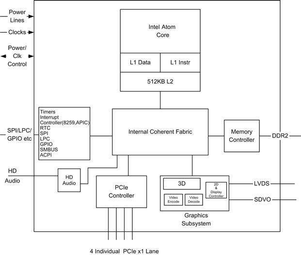
FIGURE 16.1 E6XX Series SOC.
As with all Intel platforms, I/O coherence is maintained with the processor caches. The internal coherent fabric ensures coherence between all I/O transactions to and from memory and the CPU(s) caches.
The integrated 2D/3D graphic engine performs pixel shading and vertex shading within a single hardware accelerator. The processing of pixels is deferred until they are determined to be visible, which minimizes access to memory and improves render performance. The graphics engine and display controller all use system memory (known as stolen memory). The following lists the key features of the 3D graphics engine:
• Two-pipe scalable unified shader implementation
• Fill rate: two pixels per clock
• Vertex rate: one triangle 15 clocks (transform only)
• Vertex/triangle ratio average = 1 vtx/tri, peak 0.5 vtx/tri
• Texture maximum size = 2048 x 2048
• Programmable 4x multisampling anti-aliasing (MSAA)
• Optimized memory efficiency using multi-level cache architecture
• Shading engine key features:
• Multithreaded with four concurrently running threads
• Zero-cost swapping in/out of threads
• Cached program execution model—unlimited program size
• Dedicated pixel processing instructions
The hardware video decoder supports MPEG2, MPEG4, VC1, WMV9, and H.264 (main, baseline at L3 and high-profile level 4.0/4.1)†, while the video encoder engine supports MPEG4, H.264, and H.263. It supports LVDS and serial DVO display ports permitting simultaneous independent operation of two displays.
The SOC supports a high-definition audio interface. The interface can support up to four multichannel audio streams. Each channel within the audio stream can support a 32-bit sample depth, with a sample rate up to 192 kHz.
The SMBus host interface allows the processor to communicate with SMBus slaves. This interface is also compatible with most I2C™ devices.
An SPI interface is provided and is used to boot the processor. The BIOS/firmware for the processor must be stored in an SPI-attached flash device.
The SOC has 14 general-purpose I/O pins (GPIOs). Five of these are powered by the core power rail and are turned off during sleep mode (S3 and higher). Nine of these GPIOs are powered by the suspend power well and remained active during S3. All the GPIOs in the suspend power well can be used to wake the system from the suspend-to-RAM (S3) state. The GPIO pins can also be configured to generate an interrupt to the CPU.
A JTAG interface is provided for debug using a JTAG debugger, as described in Chapter 17.
A key expansion feature is the provision of PCIe interface(s) to expand the capabilities of the SOC. It provides four x1 lane PCI Express root ports supporting the PCI Express Base Specification, Revision 1.0a. The processor does not support the “ganging” of PCIe ports. The four x1 PCIe ports operate as four independent PCIe controlled links.
Most of the internal SOC blocks that need to be visible to software are presented logically as PCI devices on PCI bus zero. They are known as root complex integrated endpoints. Figure 16.2 shows the enumeration of devices within the SOC, along with possible devices enumerated from the external PCIe buses.
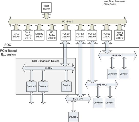
FIGURE 16.2 PCI Logical View.
Platform Controller Hub(s)
A key philosophy of the E6XX service devices is the ability to extend the platform through industry standard PCIe interfaces. At the time of writing there are a number of expansion devices, targeted at differing use cases from different suppliers. The intent here is not to replicate the data sheet but to call out some of the key attributes of the interfaces.
Intel Platform Controller Hub EG20T
The Intel Platform Controller Hub is developed as a generic device for use in general embedded cases. Its features include the following:
• Peripheral Component Interconnect (PCI)-Express, the interface to the host processor
• Universal Serial Bus (USB) Host, Interface (EHCI) (1.0) and Open Host, Controller Interface (OHCI) 1.0a, six ports (two USB 2.0 hosts; three ports for each host); provides USB port that supports high-speed (480 Mbps), full-speed (12 Mbps), and low-speed (1.5 Mbps) operations
• Universal Serial Bus (USB) device, complies with USB 2.0 and USB 1.1 protocols. Up to four IN and four OUT physical endpoints (EP0-3), which can be tied to different interfaces and configurations to achieve logical endpoints
• Gigabit Ethernet Media Access Controller (GbE MAC); conforms to IEEE802.3
• Serial Advanced Technology Attachment (SATA), SATA 1.5 Gbps Generation 1 speed and 3 Gbps Generation 2 speed, two ports (two ports with one AHCI SATA controller)
• Secure Digital (SD) host controller, conforms to Secure Digital Host Controller (SDHC) speed class 6, two SD host controllers; one port for each host), SD bus transfer mode (1-bit/4-bit/high-speed), MMC transfer mode (1-bit/4-bit/8-bit/high-speed)
• IEEE1588 block (clock synchronization), provides the hardware assist logic for achieving precision clock synchronization, conforms with the IEEE1588-2008 standard, supported on Ethernet and CAN interface
• Serial Peripheral Interface (SPI), up to 5 Mbps, bus-master function (includes a shared DMA), performs full-duplex data transfer, operates as master mode or slave mode
• Controller Area Network (CAN), CAN protocol version 2.0B Active, bit rate up to 1 Mbps, 32 message objects, priority control by each message object, detection/identification of bit error, stuff error, CRC error, form error
• Inter-Integrated Circuit (I2C) bus controller, Philips I2C Bus Specification 2.1 conformant controller; Standard mode (100 kHz) and Fast mode (400 kHz); the I2C transmitter and receiver support both master and slave devices
• One Universal Asynchronous Receiver-Transmitter (UART) with an 8-wire interface; 256-byte transmit and receive FIFOs, interoperable with 16550, modem control signals are configured with CTS (Clear To Send), RTS (Request To Send), DSR (Data Set Ready), DTR (Data Terminal Ready), RI (Ring Indicator), and DCD (Data Carrier Detect), supports the following programmable serial interface characteristics, maximum baud rate: 4 Mbps
• Three UARTs with a 2-wire interface, 64-byte transmit and receive FIFOs, maximum baud rate: 1 Mbps, interoperable with 16550
• GPIO: 12-bit general-purpose I/O ports. Input or output can be specified for each port. Interrupts can be used for all of the bits. Interrupt mask and interrupt mode (level/edge, positive logic/negative logic) can be set for all bits. GPIO0-7 correspond to WAKE-ON (GPIO8-11 does not support wake features)
• JTAG; supports boundary scan mode
• Serial ROM I/F; supports access to the option ROM of each function, loading of a parameter required for initialization of each function (GbE MAC and SATA AHCI initialization), SPI interface
Figure 16.3 shows the allocation of functions to PCIe devices/functions.
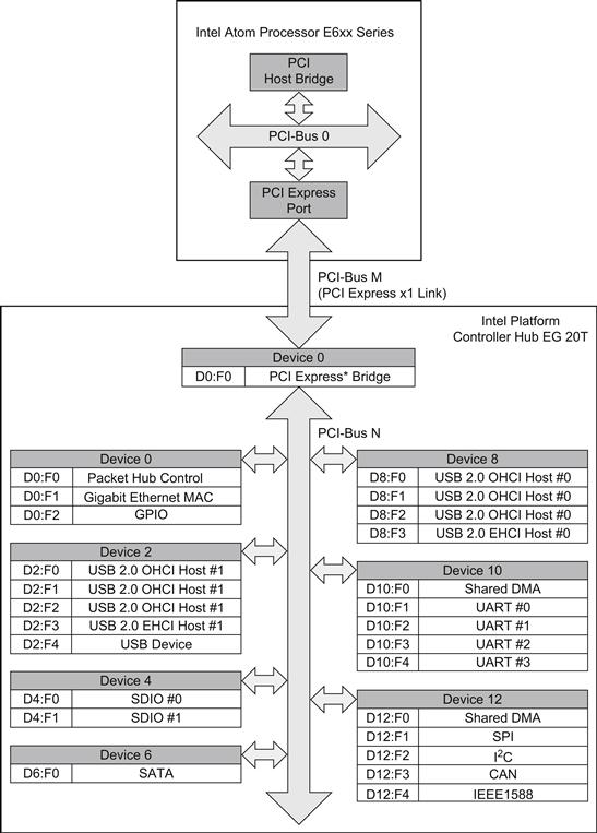
FIGURE 16.3 EG20T Platform Controller Hub.
A number of other vendors provide application-centric PCH devices.
OKI Semiconductor ML7213 and ML7213V
OKI Semiconductor has created a device for general applications, for example, in vehicle infotainment. The standard interfaces support PCI Express 1.1 x1, USB 2.0 host, USB 2.0 host/device switchable (only with ML7213), SD host (SDIO), serial ATA II, gigabit Ethernet (MAC), UARTs, SPI, I2C, I2S, and GPIO. The application-specific capabilities are the following:
• Time Division Multiplex interface (supports Multichannel Audio Serial Port, a popular interface used to connect to digital signal processors)
• Media LB™ (only with ML7213), interface to Media Oriented Systems Transport (MOST; http://www.mostcooperation.com) physical interfaces
• Security acceleration: 3DES, AES, SHA1/265/MD5 (acoustic/line echo, noise canceller)
ST Microelectronics
ST Microelectronics has created an in-vehicle infotainment targeted system. The device will include automotive targeted capabilities such as Controller Area Network (CAN), Ethernet AVB (audio video bridging), and Media Oriented Systems Transport. The device also supports the traditional interfaces such as USB and SATA.
CAN is a robust slow-speed network used in most vehicles; it is used to exchange messages between the many embedded controllers found in modern vehicles. A high-performance in-vehicle network is needed to exchange multimedia content between devices such as the head unit (the primary infotainment display visible to the driver). There are many special considerations required in the automotive environment and networks based on Ethernet AVB, a set of IEEE 802.1 standards for distributing audio and video over an Ethernet network. MOST, a high-speed network (25/50 and 150 Mbps) over an optical ring carrying both synchronous and best effort traffic, and Firewire™ are deployed. The key attribute of these networks for use in audio and video distribution is quality of service, all of which are addressed.
Discrete Device Expansion
You are not required to use a Platform Controller Hub. Given that the Intel Atom SOC provides standard PCIe interfaces, you can add almost any PCIe discrete device to the platform. For example, a SATA controller could be added with a Silicon Image SiI3132 SATALink PCI Express to a 2-Port Serial ATA II Host Controller. The devices can be soldered down on the platform or added as an add-in card through standard interfaces such as Mini PCI or PCI connectors. In fact, adding a PCIe-based module is the most typical mechanism for adding wireless capability to the platform. The development of a wireless module requires a specialized wireless skill set that may not be the core competency of the team developing the embedded system. The purchase of a wireless module significantly eases and reduces the risks of adding a wireless capability to an embedded platform.
FPGA Expansion
Most FPGA devices include PCIe interface capability at this point; you can add specific capabilities via FPGA should you need to. This is a very common expansion option used in embedded systems. Intel has released a part with a pre-integrated FPGA. The devices were formerly code-named Stellarton and are released as the E6x5C series, shown in Figure 16.4. You can, of course, use any discrete FPGA that supports PCIe. The device consists of an E6XX services Intel Atom processor along with an Altera FPGA.

FIGURE 16.4 E6x5C Series (Formerly Code-Named Stellarton) Package Partitioning.
The FPGA contains a PCIe hard IP block. A hard IP block is a block on the FPGA developed without using any of the configurable resources within the device. It is called hard IP because the functions cannot be modified. This provides the PCIe endpoint and is discovered by the PCIe enumeration process. The FPGA logic behind the endpoint block provides the configurable expansion capability. In some cases you may have a bandwidth requirement that exceeds that provided by a single PCIe x1 lane; then the programmable blocks can be attached to the processor via the second PCIe link to the FPGA. This requires that you use a soft IP PCI endpoint. The endpoint uses up some of the configurable elements in the FPGA to provide the connectivity.
Multi-Radio Communications Design
Connectivity to a device is an increasingly important aspect of embedded systems. In many cases the device has a specific embedded function and connectivity is used to provision and manage the device remotely. In many other embedded applications the purpose of the device is to mediate communications between devices and networks. A simple example of such a device is the residential gateway or wireless router in your home. This section describes the hardware and software design of a machine-to-machine (M2M) gateway design. The design has a number of communications interfaces and the associated software stacks to route between the different communication modalities.
Hardware Platform
The reference platform must communicate between 3G/4G modules. The capabilities can be provided by a using a pre-certified 3G/4G module. Having the module pre-certified can save time because certification by the appropriate certification bodies can take quite some time. The module selected for this example is an Ericsson F5521gw module. The module offers high-speed connectivity with HSPA evolution speeds: 21 Mbps downlink and 5.7 Mbps uplink. It comes in a PCI Express mini-card form factor. A local wireless interface is also needed, and in this case, both a wired Ethernet interface (from the PCH) and a Wi-Fi™ interface (which provides 802.11b/g/n and 802.11a through a Mini PCIe Wi-Fi card, in our example, an Intel 4964AGN Wi-Fi module) have been selected. The platform also requires a radio for local sensor applications. The platform requires an 802.15.4 WPAN transceiver, which supports a wide range of protocols and network topologies, such as 6LoPAN, Wireless HART, and ZigBee, using a unique 802.15.4 MAC layer interface. An example of such a radio is the TI CC2530. The device provides a USB interface to the processor.
All other platform features are similar to the traditional capabilities. Figure 16.5 shows an example of a multi-radio communications gateway.

FIGURE 16.5 Multi-Radio Communications Gateway.
The platform includes a 3G/4G wireless module, and as such is using licensed spectrum. In order to use this wireless module, a subscription is required. In the case of 3G/4G standards that are defined by the 3FPP organization you must have a subscriber identity module. This SIM takes the form of a Universal Integrated Circuit Card. The UICC smart card contains a CPU, ROM, EEPROM, and I/O. In mobile phones, it usually takes the form of a removable SIM card. In embedded platforms, the SIM function is provided by embedded IC (such as an Infineon SLM76). This device can be soldered down on to the platform.
The radios often use a number of antennas to support better, more reliable connectivity. In some cases the antennas are used for diversity, and the strongest signal will be selected from the appropriate antenna. In newer systems multiple-input and multiple-output (MIMO) schemes are used, where multiple antennae at the transmitter and receiver are used to significantly improve the performance and range of the radio.
Yet another consideration can apply if multiple radios are sharing the same wireless spectrum. This can often be the case in the unlicensed 2.4-GHz spectrum, where Wi-Fi, Bluetooth, DECT, Zigbee, and many other radios operate. In many cases the protocols are designed to gracefully degrade (each other), but the spectrum is shared. It is a good idea to read the relevant papers on Wi-Fi and Bluetooth) and Wi-Fi and Zigbee to better understand coexistence issues for the shared spectrum.
Software Platform
The Linux platform offers an excellent baseline to start development of a multi-radio gateway platform. Linux has a rich networking infrastructure that is covered in Chapter 12. Starting with the device drivers, device drivers need to be obtained for all the required radios. This has become much easier in recent times, as vendors have come to realize the importance of Linux for such systems.
Device Drivers
The status of Linux drivers is an ever-moving target. In some cases you can only get the drivers directly from the radio module provider: in others the code is staged in a project repository on a server such as SourceForge, and ideally the driver has already been upstreamed and is part of the kernel trees. If you have flexibility in device selection, it’s recommended that you identify the quality and support and distribution of the wireless drivers before selecting the hardware—a piece of hardware without a driver is not much use.
The Wi-Fi radio is supported and upstreamed in the kernel at drivers/net/wireless/iwlwifi/. More details can be found at http://intellinuxwireless.org/.
The Ericsson F5521gw drivers are (at the time of writing) in the kernel but also use a staging area at SourceForge. The project is known as Mobile Broadband Modules.
The availability of 802.15.4 drivers is a little less mature then the other subsystems but they are being actively developed. The IEEE paper “How to become an IEEE 802.15.4 expert” is an excellent introduction to IEEE 802.15.4.
The device selected above to provide the 802.15.4 radio capability is the Texas Instruments CC2531, which provides a USB device interface that is presented to the host as a standard USB Communication Device Class (CDC) capability. As such, the standard Linux CDC Class driver provides the serial abstraction to the devices. The ZigBee stack itself is an open source stack such as FreakZ (http://www.freaklabs.org).
Network Stack
The networking stack is a critical element of a gateway function. The stack supports bridging (at Layer 2) between Wi-Fi and Ethernet attached devices. For packets targeted at the gateway, the packets are routed up the TCP/IP stack. The stack can also perform IP routing and network address translation for packets to and from the WAN (3G/4G) interface.
Host Access Point
You may wish to allow 802.11 wireless devices to connect to the gateway. This can be supported in two ways; the first is through a peer-peer connection, but it is more typically done by supporting access point mode in the gateway. The HostAP module allows many Wi-Fi modules to be configured in access point (infrastructure) mode. This allows appropriately configured Wi-Fi–based devices to connect to the gateway.
Connection Management
It is useful to provide a mechanism to manage the connection on the platform. A number of open source projects support the configuration aspects of wireless connections and maintain such communications. The connman (http://www.connman.net) project is one such project, and network manager (http://projects.gnome.org/NetworkManager/) is another.
Security is an important aspect of any platform that provides remote access capability. It best to use OpenVPN to secure communication between the device and any remote user.
802.15.4 Stacks
There are a number of different protocols that all use the 802.15.4 layer: 8LoPAN, Ipv6 Over Low Power Wireless Personal Area Networks, and Zigbee. At the time of writing, the 802.15.4 stack development, device support, and upper layer support are still an active area of development within the kernel.
Web Server
A web server process is a straightforward mechanism to communicate with the gateway remotely. The platform must run a web server. Apache is a mainstream web server that is widely deployed; however, it may be too resource heavy for embedded systems. There are many servers targeted at embedded platforms, such as lighttpd. The ability for a server to support CGI or PHP scripts is important because it allows a simple mechanism to convert actions performed on the web page into actions on the gateway device itself. The support for https is also a key consideration to allow secure communications with the web server.
Application
The routing functions of packets will take place automatically by the Linux infrastructure once set up. The setup can be controlled by scripts and managed by the web server though a component such as webmin (with the appropriate plug-ins). If the application must translate between commands on the web interface into messages directed toward PAN devices, then it is likely that the application must mediate and translate between these domains. The translation function can be written in a native application using C, or as often the case, in a scripting language. The language Lua is popular for such embedded control applications.
Figure 16.6 shows the some of the key components used to create a web-managed multi-radio gateway device.
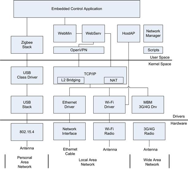
FIGURE 16.6 Multi-Radio Gateway Components.
In many cases, a large number of embedded devices (as in millions) need to be managed remotely. To facilitate large-scale remote management, a vast range of web-based management agents are available that can be overlaid on such a platform. The traditional 3G/4G device management is carried out through OMA-DM standards defined by the Open Mobile Alliance (OMA). In wire-based applications such as DSL modems or cable set-top boxes, the Broadband Forum Technical Report 069, known as the TR-069 specification, defines the protocol and mechanisms to manage customer devices by the infrastructure providers.
Multimedia Design
Many embedded systems are convergent with consumer devices. High-resolution displays with touch control are now commonplace; examples can be found in in-vehicle infotainment systems, home automation/security systems, and media phones. A media phone is a cross between a traditional phone and a tablet. The attributes of these reference designs are similar to many embedded devices. Let’s first outline some high-level features for the platform:
1. Support for downloadable applications or widgets to extend the capabilities of the platform
2. Support for calendar and mail applications
3. Playback of high-quality media from local and remote streaming from local and Internet sources
5. Enable intent applications such as Pandora
6. Provide DECT-based telephony handset
This is just an overview; in reality, a product in this class would have a product requirements document (PRD). This is the starting point for any project; you should have an idea of what you are building before you start. In many cases you will also integrate through the design so the PRD is an active living artifact that you update as you go. The first step is to identify the hardware capabilities needed to meet the high-level feature set.
Hardware Platform
The first item to select is the base line processor. Since the Intel Atom processor is the reference in this book, the design will be based on the E6XX service device, along with the general embedded PCH (EG20T). This will provide the following:
• Core processor (Intel Atom); offers a large range of software to select from
• Display and graphics controller; high-resolution display with sophisticated 3D transitions along with alpha blending are common expectations
• Hardware decode engine; smooth playback of high-definition streams are computationally expensive, and the use of a hardware decode pipeline makes it possible to free up CPU cycles for other aspects of the application
• Hardware video encode engine; video encode can be even more costly (in terms of CPU computes) than video decode. The video encode can be used to encode a captured video stream from a local camera
• Mass storage interfaces; SDIO or SATA can be used to provide OS, application, and data storage for the platform
• Ethernet connectivity; it is beneficial to offer a physical connectivity option to the design; in some environments the use of Wi-Fi to provide telephony services does not work well (particularly in cases of interference or a loaded network)
• HD audio interface; can be used to locally connect speakers and microphones
The platform still requires a touchscreen interface, a DECT, and Wi-Fi interfaces.
A touchscreen interface chip depends on the selection of touchscreen technology; for consumer-oriented cases, capacitive touchscreens are commonplace. The touch controller interfaces to the core processor via the SPI or I2C interface. This example employs the SPI interface using the ST Microelectronics STMT07 S-Touch™ FingerTip multi-touch capacitive touchscreen controller. The recognition of gestures (particularly multi-touch) on the touch device is often carried out by the controller, so you should consider the features supported prior to selection.
The DECT controller can be attached via USB or SPI. We have chosen a USB controller to allow both data and voice to be transferred to the DECT handler. We don’t go into the DECT handset design at this point. When using USB we must ensure that the voice is carried over isochronous endpoints to ensure low-latency deterministic voice data transfer. In some designs, SPI may be a better choice.
We also need some simple push button controls for some aspects; these are attached via GPIO pins.
Putting it all together gives the diagram shown in Figure 16.7.
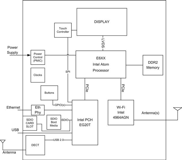
FIGURE 16.7 Media Phone Reference.
The following section will delve into the software component selection.
Software Platform
In many modern software development challenges you will not be developing the entire system software from scratch. In fact, that is a very poor use of your time. The objective should be to reuse as much preexisting software as possible and focus on what differentiates your particular product. This reused software could take the form of open-source software, driver or enabling software from the different silicon vendors, or purchased software components.
The software within the platform can be broken down into layers within the overall software design:
• Core platform software, operating system, and all associated device drivers, power management, file systems, and display system.
• Platform middleware and frameworks, the collection of libraries and frameworks that can be used to build higher-level applications, for example, a media framework such as GStreamer, telephony solutions such as Telepathy, optimized libraries for DSP voice processing, and 3D/2D APIs. An interprocess communication (IPC) framework is also critical in developing and coordinating the activities of the higher-level applications; DBUS provides such a capability.
• The overall user experience is generated by a number of separate applications, each written to support a specific feature/user experience. For example, a media player is separated and distinct from the telephone dialer. It is very useful to use a Model View Controller (MVC) design pattern when developing applications that are run on such a system. For the media player example, the application should consist of a separate media playback engine that takes care of rendering/playback of media on the required outputs, while taking all control input via an IPC mechanism. The user interface of the media player can then be written and developed (personalized/skinned) separately. It allows for sophisticated use-case behavior to be integrated into the overall experience—for example, the telephone stack can pause the media when an incoming call occurs.
• Home screen and application coordinator. At least one primary application should take ownership of the home screen; it will contain a mechanism to launch applications. In many cases portions of the screen will continue to be owned by the home application (for example, a banner).
Figure 16.8 shows the components selected and their relative positions in the stack.
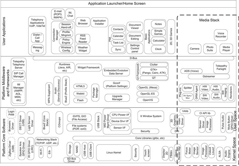
FIGURE 16.8 Multimedia Software Platform (Based on Linux).
Figure 16.8 is an extreme simplification of the overall system; it can take considerable effort to select the capabilities and integrate them into an overall solution.
Figure 16.9 shows a high-level overview of the audio path interactions in the system. The incoming audio samples are captured from the DECT device driver and then routed through the Linux ALSA and PulseAudio frameworks. The application routes the audio samples to the telephony/VOIP stack where the packets are encoded using a codec such as G.729a. Once encoded, the samples are sent to a real-time protocol (RTP, a transport protocol for real-time applications—IEFT RFC 3550) stack to be encapsulated in packets to be streamed toward the Internet VoIP service provider (such as Vonage in the United States).
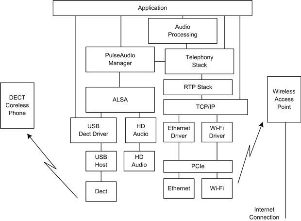
FIGURE 16.9 Audio Data Path from DECT to VOIP Interface.
As you can see, the system is built up from a large number of components with complex interactions. There is a truly staggering amount of code that can be reused in the creation of sophisticated embedded systems. This is particularly true for IA-32-based systems because the vast majority of the code has already been targeted to IA-32 systems, albeit desk/notebook/netbook–based systems. Having said that, many of the packages are also validated on other CPU architectures.
Modular References
A variety of modular form factors are used in embedded systems. Such systems define a key interface connector between the compute board and the expansion or application specific board. The compute boards are offered with a variety of CPU configurations, which allows the embedded system designer to upgrade the capabilities of the system without a significant redesign of the application-specific design each time. There are a number of such connector standards, two examples being Com Express (http://www.picmg.org/) and QSeven.
The Inforce computing (http://www.inforcecomputing.com) E6XX series module is a good example of the type of module available. Figure 16.10 shows the module break down.
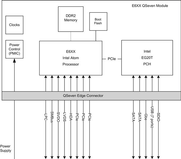
FIGURE 16.10 E6XX QSeven Module Block Diagram.
The platform is then expanded using various base boards. Because the connector is standard, different carrier boards can be used.
Given that the board shown in Figure 16.10 exposes many of the standard Intel architecture platform interfaces, the platform just requires a BIOS/firmware image (provided) and will boot a standard Linux, Windows, or RTOS as needed.
Summary
There is such a broad range of embedded applications, it is impossible for any chapter or book to do justice to the entire landscape. In this chapter we have touched upon just a tiny subset of such embedded platforms, attempting to select some key attributes of modern embedded systems.
It is key as an embedded systems developer to understand the system at a component level and to integrate the subsystems into an overall functional system. In many cases this involves device and component selection. When doing so it is important to also consider the software availability or development costs for devices/components selected. In many cases, the required device drivers are available from the device provider; however, it is often the case in embedded systems that no such driver is available and you must develop it yourself. All such considerations should be incorporated into the overall system design.