
Chapter 8
Embedded Linux
This chapter provides an overview of the Linux capabilities you should be familiar with in order to develop embedded Linux systems. It covers aspects such as cross-development tool chains, configuring and building the Linux kernel, development of a simple character device driver and provides an overview of some key kernel services that can be used within your device drivers.
Tool Chain
In order to build the operating system and applications, you need a tool chain. The tool chain provides the assembler, compiler, and linker, along with a number of other utilities needed to develop a Linux-based system.
The most common tool chain used in Linux systems are the GNU tools. The compiler is provided by GNU Compiler Collection (GCC) (http://gcc.gnu.org/), and the assembler, linker, library, and object manipulation tools are provided by the GNU binutils project (http://www.gnu.org/software/binutils/). These tool chains are available in source form but in many cases are also available in binary form. It is simple to install GNU toolchains on a Linux desktop distribution. Desktop distributions include a software package manager such as apt for debian-based hosts or yum for rpm type distributions. The command sudo apt-get install gcc will install the IA-32 GCC binary tool chain for a debian/Ubuntu-based system.
When you install a tool chain as shown above, you are downloading a binary version of the tool chain from a repository. The binaries were configured and built from a source for the target system you are downloading to. This build process and hosting is carried out by the repository maintainer. Normally, the tool chain being installed has been configured to compile and build applications with the same environment (processor type, 32-/64-bit, and so on) as the host downloading the tool chain.
Let’s take a moment to define host and target. The host machine is the machine you develop your applications on. In most cases today that will be an IA-32-based machine running a desktop distribution of Linux such as Fedora/Centos, Ubuntu, or SUSE/OpenSuse. In most examples used in the text, we have used an Ubuntu desktop distribution (with no real rationale or preference). The target device is the actual embedded device that you are developing the software for. The device could be based on IA-32, ARM™, MIPS™, PowerPC™, or any of the other CPU architecture supported by Linux. When the host and target architecture are the same, you are said to be doing native development; however, the target platform architecture does not have to be the same as the host platform architecture (for example, CPU IA-32). When the host and target platforms differ, you are said to be doing cross-development. In this case the tool chain that you download and run on your host must be a specialized version capable of executing on the host CPU architecture but building for the target CPU architecture. All of the GNU tools support both native host development and cross-development configurations. If your target embedded device is IA-32 and your host is IA-32, it is still advisable to create a tool chain dedicated to your target and not to rely on your host tools chains. It is convenient for early development, but can cause issues later in the development cycle.
Note
When you develop and release an embedded system, you would normally be very diligent about using a source code control system. At the point of release, you should tag the source code with a particular version. You will also be expected to rebuild the target image at a later point (to fix bugs and such). To recreate the target image, you will need to recover every aspect that went into creating the target image; that includes sources, binary libraries, and even the tool chain that you used to create the image. To facilitate that, you should also always archive the tool chain used at the time of release. If you rely on the host-based tool chains, you may have upgraded to a new version of Linux and a corresponding new tool chain. Should this occur, you will not be able to recreate the exact image you previously shipped; in some cases it may not even compile again. A number of open-source source code control systems are available, such as GIT, Subversion, Mercurial, and CVS.
Getting the Tools
You can download the source code for binutils and gcc and build the tool chain yourself. This can often be very tricky and takes many separate stages (consider the problem of creating a compiler without first having a compiler). There are a number of scripts that greatly simplify the generation of the tool chain. At the time of writing, the crosstool-NG is a good option if you just require a tool chain. It cross-builds the tool chain for all architectures supported by GCC. The ct-ng menuconfig line is where you select the target CPU architecture. Below is a Mercurial source code control command to get the source from the source repository system.
>hg clone http://crosstool-ng.org/hg/crosstool-ng
>./configure --prefix=/some/place>make
>make install
>export PATH="${PATH}:/some/place/bin"
>cd /your/development/directory
>ct-ng help
>ct-ng menuconfig
>ct-ng build
There are four key attributes of the target tool chain that must be selected:
• The target CPU architectures (for example, IA-32, ARM)
• The application binary interface (ABI)/calling conventions (for example, fastcall, X.32, System V AMD64 ABI convention, and EABI)
• Object format (for example, ELF)
• Target operating system (for example, bare metal/Linux). This is important for calling conventions used to interact with the system.
The output of the build process is placed in your home directory in an x-tools folder. Each tool chain that you select is placed in a configuration specific folder. For example, a generic IA-32 tool chain is placed in the ~/x-tool/i386-unknown-elf/ folder, and a generic ARM tool chain is placed in ~/x-tools/arm-unknown-eabi folder. In addition to the target architectures, the target application binary interface must also be selected for the tool chain to use. The ABI defines all semantics associated with the construction of binary objects, libraries, interfunction calling mechanisms, calls to operating system services, register usage, and the like.
There are two versions of ABIs in use on IA-32 systems, a 32-bit and a 64-bit version. The 32-bit version of standard can be found at http://www.sco.com/developers/devspecs/abi386-4.pdf and the 64-bit version http://www.x86-64.org/documentation/abi.pdf.
Note
For many years, IA-32-based processors have supported two ABIs, the 32-bit and 64-bit ABI. Work is under way to develop a hybrid of the two ABIs (called X32) to maximize the use of registers in a 64-bit CPU but avoid much of the porting difficulties when porting applications from 32-bit to 64-bit environments. When using the X32 ABI, all ints, longs, and pointers are restricted to 32 bits, even though the code will execute on a 64-bit machine. Many of the porting difficulties between 32-bit and 64-bit are as a result of the type size change. There can be a reluctance to migrate to 64-bit, particularly since the traditional advantages of moving to 64-bit do not apply to many embedded systems. In the case of IA-32, however, there are far more registers available in 64-bit mode. The X32 ABI maximizes the use of all processors’ registers in the 64-bit-enabled CPU. The OS itself must be run in 64-bit mode to take advantage of this ABI. Kernel updates and so on can be found at https://sites.google.com/site/x32abi/documents. Intel® Atom™ processors support both 32-bit and 64-bit modes.
The default ARM tool chain application binary interface is the Embedded Application Binary Interface (EABI). It defines the conventions for files, data types, register mapping, stack frame and parameter passing rules. The EABI is commonly used on ARM and PowerPC CPUs. The ARM EABI specification can be found at http://www.arm.com.
The primary object format is defined by the Tool Interface Standard – Executable and Linking Format (ELF) (http://refspecs.freestandards.org/elf/elf.pdf.) The standard is composed of books that define the generic ELF format, along with extensions of processor architectures and target operating systems.
In some cases, there is no target operating system specified or used; this is in effect a generic target. Most tool chains support a non-OS-specific processor-specific target option. This is sometimes known as bare metal.
Tools Overview
The tools used/required in embedded systems go beyond the traditional compiler and linker. There are a number of cross-development tools generated that are part of the GCC family, as shown in Table 8.1. A review follows of the capabilities of each tool and what each is used for.
Table 8.1. Cross-Tool Chain Programs.
| Executable | Description |
| addr2line | Converts an address into a file name and file line number. It uses debug information to figure out the file name/line number from the executable. This is very useful for debugging crashes, as it can be used to narrow down and find the cause. |
| ar | Creates, modifies, and extracts from archives. An archive is a collection of objects or libraries. It provides a simple way to distribute a large number of objects/libraries in a single file. |
| as | The GNU assembler. The assembler can be used natively and is used to assembly the output of the GCC compiler. |
| C++filt | Demangles C++ and Java symbols. C++ and Java languages provide function overloading. This demangles the auto-generated (managed) names produced by the compiler into a human-readable form. |
| cpp | The C preprocessor, the MACRO preprocessor used by the C compiler prior to compilation. It expands macros, definitions, and so on in the code. The C preprocessor can also be used as a standalone tool. |
| gcc | The GNU C and C++ compiler. The default invocation of cc performs preprocessing, compilation assembly, and linking to generate an executable image. |
| gcov | Coverage testing tool. Use this tool to analyze your programs, create more efficient code, and discover untested portions of code (from http://gcc.gnu.org/onlinedocs/gcc/Gcov-Intro.html#Gcov-Intro). |
| gdb | The GNU debugger. It can be used for application/user space and kernel space debugging; it can also be used to communicate with target debug hardware such as JTAG ICEs. IDE wrappers such as DDD also exist to improve usability, |
| gprof | Display call graph profile data. Profiling allows you to examine the amount of time spent in certain functions and frequency of function calls being made. |
| ld | The GNU linker. The linker combines objects and archives, relocates their data, and resolves symbol references. A map file of the resulting output can be generated and is very useful in understanding the layout of the application. |
| nm | Lists all the symbols from objects. |
| objdump | Displays information from object files: objdump –S <file> dumps the entire object and displays the disassembly object and where possible interleaves this with the source code; objdump –s vmlinux generates a useful file for debugging kernel oops (at least for the statically linked kernel elements). |
| ranlib | Generates an index to the contents of an archive and stores it in the archive. |
| readelf | Displays information about ELF files, similar to objdump but displays additional information. |
| size | Lists the size of sections and to the total size of an object/executable. The sections are text, data, and bss. The text section is where the code resides, data is where global and static variables that are program initialized such as char str[] = "hello world" are stored, and bss are uninitialized variables, such as a global or statics that are not initialized or initialized to zero. The startup code for an application clears the bss section. |
| strings | Displays any human-readable strings from a file. For an executable or object, it displays strings in the code and any symbol strings in the object. |
| strip | Removes symbol information from object files. |
The most commonly used programs for an embedded developer are set in boldface in the table, namely, ar, as, gcc, ld, and objdump.
Once you have acquired the appropriate tools, make sure you set the path to them and archive a copy when you release your software.
Anatomy of an Embedded Linux
There are a number of components within an embedded Linux system. The focus of this discussion will be on the aspects that an embedded developer is most likely to interact with.
The first key component is the Linux kernel itself. The source code for the Linux kernel is always available from http://www.kernel.org. The site contains both mature and bleeding edge versions of the kernel. In most cases you should pick the latest mature kernel to start your work. The kernel source tree includes all the code for the kernel itself along with device drivers and platform support code. Prior to selecting the kernel version to use you should review the major kernel features (by reading the kernel mailing lists and so on) to ensure that the major kernel features you wish to use are in the current version. Generally speaking, embedded systems are not developed using all the latest and greatest kernel features, but there could be a specific item you wish to ensure is available.
If your platform is very new, the drivers for your platform may not actually be in the mature branches of the source tree, and you may have to choose a kernel version that is a little less mature. In general, device drivers are developed and submitted for inclusion in the kernel source tree using the latest kernel version. If you choose to develop your platform on an older kernel version, you may have to “backport” the driver from the staging or later kernel versions to the one you choose. In most cases, your software development is likely to remain on the same kernel version for quite some time. In some cases there are bugs in the kernel that are discovered and fixed in later kernel versions. You should track the major bug lists/reports for the kernel to ensure that your system does not ship with a known serious bug or security issue. You should make the same changes (backport) to your kernel version (if it is possible) or upgrade. Clearly, the closer you are to shipping your embedded system, the less churn you can introduce into your system, so selective backporting is best as you approach product release.
Although the entire codebase (source code) is free to download and use, in the context of product delivery and maintenance, an embedded project team should dedicate resources to the selection and constant tracking of the kernel. Building your own kernel and maintaining it internally for your product use is known as “role your own”. In some projects, you may choose to go with an operating system provider such as MontaVista, TimeSys, or Wind River. There are many aspects to the decision of whether to “roll your own” (RYO) or select a commercial offering. A lot will depend on where you and your team need to focus your resources. You should be aware that the traditional desktop distributions such as Ubuntu, Fedora, and SUSE are generally not well suited to an embedded system.
We touched on device drivers and platform support above. If you are using a device (such as a wireless chipset or SOC) that has been in the market for some time, the driver is most likely obtained directly from the kernel source tree. In some cases, you may have to obtain the driver from a silicon device manufacturer. This would be from the vendor’s site or other hosting locations such as SourceForge. Failing that, or if you are developing your own hardware, you will have to develop the device drivers yourself. Once you have developed a driver for a target hardware device, you may elect to upstream the driver. This is a process where you submit the driver to the appropriate kernel mailing list to be vetted and approved by the subsection maintainer for inclusion. It is strongly advisable to start this process well in advance of designing your driver. There are many criteria that the upstream maintainer may apply to code that they accept; it’s not advisable to go off and create a sophisticated device driver in a silo and then attempt to throw it upstream. Do your homework, read the mailing lists, look for design patterns in previously submitted/accepted drivers, and engage with the subsystem maintainers. There are a lot of long-term advantages if you upstream the driver: the code is automatically distributed with the kernel, and you may get help maintaining the driver when the kernel is updated to a subsequent revision.
Once you have the kernel and appropriate device drivers for your platform, you will need to decide on a root file system. The root file system contains the user space applications and libraries, services daemons, and initialization scripts/programs that your embedded Linux system will need. The basis format of a root file system is described below.
Much of the user space applications and libraries are packaged up using a package manager. There are two main types of package formats/tools at this time: Debian (DPKG) and Redhat (RPM). Each format allows you to combine a number of target files together and distribute them as a single entity. The package format includes details such as version, contents, and critically dependences on other packages. You can get a sense of the number of pages in the desktop build by entering >dpkg --get-selections in an Ubuntu system. At the time of writing, this command listed 1477 packages installed in an Ubuntu 11.04 release. Each of the packages describes the files associated with the package. Installing the package will install all of the files in the package in the corrected locations as specified by the package. In addition, the package manager ensures that critical dependencies are also installed if possible. For example, the bash shell output is shown below.
>dpkg --listfiles bash (simplified output)
/bin/bash
/etc/skel
/etc/skel/.bashrc
/etc/skel/.profile
/etc/skel/.bash_logout
/etc/bash.bashrc
/usr/share/man/man7
/usr/share/man/man7/bash-builtins.7.gz
/usr/bin/bashbug
/usr/bin/clear_console
/bin/rbash
/bin/sh
/usr/share
/usr/share/doc
/usr/share/doc/bash
/usr/share/doc/bash/CHANGES.gz
Even the simplest package such as bash includes many files that you would not need in an embedded system. Embedded systems should only include the capabilities needed for the function of the embedded system (and some occasional debug/diagnostics capabilities).
Each package itself may have a dependency on other packages. An easy way to visualize these dependences on Ubuntu is using a combination of debtree and dot. The following command generates a png file (shown in Figure 8.1) for the component bash: (You should try the command on more complex packages such as bluez).
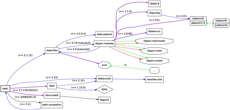
FIGURE 8.1 Package Dependencies for the Bash shell – Bash Package.
debtree bash | dot -Tpng -Obash.png
Building a file system with the required packages and all of the associated dependences requires a deep knowledge of the system; it can be challenging to ensure that the entire system created is consistent. For embedded systems it is often a requirement to be able to reproduce all binaries in the system that ships in the system. This involves using the source code version of a package and generating the binary package. You may already be familiar with installing binary packages on Linux systems. However, in this case a third party has taken care of building the binary packages from the source. It’s a more difficult challenge to have to configure and rebuild every binary/object used in the system.
As you can see, the selection and development of an embedded system from scratch is a very challenging task. Luckily, a number of projects have been created to simplify the development and use of Linux in embedded platforms. These are not actual Linux distributions, but they allow you to tailor and define the contents of your embedded system with very fine granularity. The following are some key open source projects in use:
• Buildroot (http://buildroot.uclibc.org/) is a set of makefiles and patches that makes it easy to generate a complete embedded Linux system.
• The Yocto Project™ (http://www.yoctoproject.org) is an open source project that helps you create a custom Linux-based system. The Yocto Project is a workgroup under the Linux foundation (http://www.linuxfoundation.org/collaborate/workgroups/yocto).
• OpenEmbedded (http://www.openembedded.net) is a build framework for embedded Linux. It also allows developers to create a complete Linux distribution for embedded systems. At the time of writing, the Yocto Project and OpenEmbedded projects have converged on common build tools and core package metadata, and have some shared governance.
There also more formally supported/funded projects such as the Linaro project (http://www.linaro.org).
These projects allow you build embedded systems. In all cases they provide a wide range of board support packages that include all the required drivers for a number of existing embedded platforms. The tools also help in the creation of the root file system needed to run a Linux system.
After having acquired some insight into developing an embedded system using Linux, you should consider the most expedient path to creating your baseline system. You should also consider commercial offerings of embedded Linux distributions, where there are defined support options.
Building a Kernel
Although you may use some tools such as the Yocto Project to build your target platform images, it is a good idea to understand the underlying steps involved in configuring and building the actual kernel.
Kernel Build
Building the Linux kernel from source is a relatively straightforward process. You must first download the entire source tree for the Linux kernel. The kernel source tree consists of all the source code for the kernel and device drivers for all supported processor architectures. The original kernel was developed to support 32-bit IA-32-based systems (starting with the 80386). At this point it supports all Intel architectures from the 80486, Intel Atom, Intel Core™ family, and Intel Xeon™—in both 32-bit and 64-bit modes. The kernel itself is remarkably portable, and at the time of writing the kernel source tree supports the following systems in additional to the IA-32-based platforms: Alpha™, AXP™, Sun Spark™, Motorola 68000™, PowerPC, ARM, Hitachi SuperH™, IBM S/390/ MIPS, HP PA-RISC™, AMD IA-32-64™, ASOC CRIS™, Renesas M32R™, Atmel AVR32™, Renesas H8/300™, NEC V850™, Tensilca Xtensa™, and Analog Device Blackfin™ architectures.
Kernel Steps
1. Download the kernel source directly from kernel.org. You should pick the latest stable, then un-compress and use tar to extract the kernel.
> bunzip2 linux-2.6.38.4.tar.bz2
> tar -xvf linux-2.6.38.4.tar
> cd linux-2.6.38.4
> ls
arch Documentation init lib README sound block drivers ipc MAINTAINERS REPORTING-BUGS tools COPYING firmware Kbuild Makefile samples usr CREDITS fs Kconfig mm scripts virt Crypto include kernel net security
In addition to specifying the processor architecture that the kernel supports, specific platforms or boards are also supported in the source tree. In general, the vast majority of IA-32-based platforms are supported by default (primarily due to the platform level consistency of all IA-32 platforms). The IA-32 processor-specific source is primarily found in linux-2.6.38.4/arch/IA-32. For non-IA-32 architecture, the source tree usually contains a directory entry for the SOC along with board-specific variants. For example, the XScale IPX400 BSP code is primarily located in the linux-2.6.38.4/arch/arm/mach-ixp4xx/.
Another key directory in the kernel tree is the linux-2.6.38.4/drivers tree. This portion of the source tree provides device drivers. Depending the architecture, the drivers required to support an SOC device may be in the driver tree area or within the platform directories. Figure 8.2 shows a selection of the kernel source tree most likely to be updated for platform or processor changes.
Note
There are a number of very useful Linux code cross-reference web sites such as http://lxr.linux.no/linux/ and http://lxr.free-electrons.com/source/. Such sites can be used to help navigate the kernel source tree.

FIGURE 8.2 Sample Directories in the Kernel Tree.
Kernel Options
There is a wide range of kernel configuration items that can be selected prior to the build phase. The build system is controlled by the contents of a .config file in the root directory of the kernel tree. The configuration file itself can be generated by issuing the make menuconfig command. The configuration items can be selected using the menus presented.
Kernel Steps
2. Run the tool to create the kernel .config:
make menuconfig
ls .config
.config
Figure 8.3 shows the initial screen for the make menuconfig. If you simply select exit, the command will generate the default kernel configuration. There are other graphics variants that you can use to configure the kernel make xconfig and make gconfig, which just use different graphics tools kits for the menu structure.

FIGURE 8.3 Screenshot of make menuconfig Command.
The default .config file can also be created by issuing the make defconfig command.
There is truly a very large number of configuration items; the default .config currently has over 5000 entries. You should not directly edit the .config file; you should use the configuration tools to make such modifications, because the configuration tool ensures that any dependent configuration items are also configured appropriately. Making direct modifications to the .config file may result in a configuration that fails to build or even crashes at runtime.
There are three types of options generated in the configuration (.config) file.
• CONFIG_FEATURE_XX=y. This means that the feature is built into the kernel at build time. The feature cannot be updated without updating the kernel itself.
• #CONFIG_FEATURE_XX is not set. The # symbol is indicates the remainder of the line is a comment; as a result the CONFIG item is not included.
• CONFIG_FEATURE_XX=m. This item includes a feature as a dynamically loaded module. The feature is not statically compiled into the kernel. The modules are stored on the root file system and loaded automatically as required during the boot sequence. They can be updated without rebuilding the kernel. Not all features can be built as a module instead of being statically linked. There can be a number of static dependences in the build that prevent you from turning a capability from a statically linked item into a dynamically loaded one. In general, the dynamically loaded modules are used for device drivers. This allows a standard kernel with dynamic support for a huge number of devices to be developed. The kernel size remains small, and the required device driver modules are simply stored on the root file system; on embedded systems you can prune the modules to just the devices that must be supported on the platform.
Note
The Linux kernel provides a dynamic loader. A dynamic loader is a program that takes a module and updates all the external symbol dependences to that of the currently running kernel. The module can then be used in the kernel. The kernel maintains a list of symbols and the address of each symbol to achieve this. You can display the kernel symbols using:
> more /proc/kallsyms
c0100000 T startup_32
c0100000 T _text
c0100079 t bad_subarch
c0100079 W lguest_entry
Changing a configuration option is as simple as selecting the required option in the configuration tool prior to building the kernel.
The design pattern for configuring the behavior of the system in a static manner by setting compile time variables in a configuration file is a common one. Kernel or driver code must use the resultant #defines to alter the behavior of the kernel at compile time. There are also runtime controls that may change the behavior of the system. In the case of ARM BSPs, for each ARM platform there are platform-specific definitions that are generated from definitions in the file linux/arch/arm/tools/mach-type. For example, on an XScale Intel IXP435 BSP the following run/configuration values are created:
• machine_is_ixp425() – A runtime function that is defined and will return true if the function executes on the target platform.
• CONFIG_MACH_IXP425 – A #define configuration that can be used for code that is specific to the standard IXP425 reference board.
• MACH_TYPE_IXP425 – A #define configuration that can be used at compile time to select code to run for this machine type (IXP425 reference board).
3. To build the kernel (using four processes):
Make –j 4
This will generate a linux/arch/IA-32/boot/bzImage and a system map file in the linux direcory.
file bzImage
bzImage: Linux kernel IA-32 boot executable bzImage, version 2.6.38.4 ( user@ubuntu ) #3 SMP M, RO-rootFS, root_dev 0x801, swap_dev 0x3, Normal VGA
The bzimage file consists of a compressed kernel and startup code that is used to decompress the kernel image. The map file is created for the compressed kernel image when it is decompressed into memory (shown in Figure 8.4). A map file is a list of addresses and an associated program symbols. The Linux kernel map file is system.map.
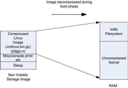
FIGURE 8.4 Linux Compressed Images.
If you have ever booted a Linux kernel, especially on an embedded system, you may have seen a series of dots on the screen (“....”). This is the decompression phase of the boot sequence.
There are two reasons to compress the kernel image (and initial RAM file system). The first reason is to save on the storage requirements for the kernel. In embedded systems the kernel is usually stored on a flash device (although general mass storage is also an option). The second reason to use compression is boot speed; a compressed kernel requires less I/O to get it off the storage device into memory, and the decompression carried out by the CPU runs quickly. The time taken to read and decompress a compressed image is less than the time to read a larger uncompressed image.
There are also options in many embedded systems to keep the image uncompressed and run the kernel from flash without first copying to memory. This is known as execute in place (XIP). XIP saves overall RAM as the kernel remains on flash; however, since the flash image is not compressed, it requires additional flash space. The performance of such systems is often lower than non XIP based systems as read access times to flash memory are typically slower than those of DRAM.
Root File System Build
The root file system is the file system you will see if you launch a shell or login to a Linux-based system (host or target) and then change directory to the root via the command
cd /
The file system layout in most cases will follow the layout defined by the Filesystem Hierarchy Standard (FHS). The FHS is standardized as part of the Linux Standard Base (LSB) (http://refspecs.linuxfoundation.org/fhs.shtm). If a distribution indicates that it is compliant with an LSB version, then the file system layout will also follow the specified FHS. In many embedded systems, the FHS is not followed exactly, as the root file system is trimmed significantly.
Creating a root file system for a full distribution is a very challenging task. The distribution could contain thousands of packages, all of which must be selected to ensure that all of the dependences and versions are correctly aligned. If your embedded system requires a significant number of packages and capabilities such as a window manager, graphics frameworks, and so on, you should start from an existing distribution. Meego, Yocto Linux, or Open Embedded would be good starting points for a sophisticated multimedia embedded platform. There are, of course, a number of commercially supported embedded distributions that are available, such as MontaVista Linux and Wind River Linux, all such distributions provide tools to build the root file system and manage the contents of the root file system (with an aim to tune the contents of the file system).
The FHS based file system follows the directory layout below:
• /bin – The programs that are normally accessible by all users are stored here. For example, shell-sh or busybox.
• /dev – This contains special block/character device and named pipe files. For example, the file /dev/tty0 is a special file to access the serial port on tty0. The mknod command can be used to create these special files. When you create such a file, you must provide a device major and minor number. This can be used by the kernel, which associates a specific device driver to the special file. (More on the assignment of these numbers follows later in the chapter.) There are even special files that can be used to access the entire physical memory from user space (/dev/mem).
• /etc – This is the general configuration storage directory, such as the password file and dhcp/network configuration information. Scripts to boot up the system are often executed by the init program (see below).
• /lib – The shared libraries for other programs are stored here. Using shared libraries significantly reduces the storage requirements on the system. If all shared library content were linked directly to each and every application (that requires a library), the file system would be significantly bloated.
• /lib/modules – This holds the loadable device drivers in the form of kernel modules.
• /proc – This is a virtual file system used to provide information about the system. For each file there is a corresponding set of functions that are called in the kernel. A device driver can install a handler for a particular file name in the /proc folder. There is a lot of interesting data that you can obtain from the /proc file system; for example, the CPU information can be obtained by issuing the cat /proc/cpuinfo command at the console. The /proc file system can also be used to configure aspects of the kernels behavior; for example, you can enable TCP/IP forwarding between network ports by issuing the echo 1 > /proc/sys/net/ipv4/ip_forward command. The proc file system provides very accessible mechanism to control aspects of your driver at runtime as well as display information from the system in a simple way.
• /root – This is the home directory for the root user.
• /sbin – Programs that are normally run by the system, or as root, are stored here. The init program is stored here; this is the first process to be executed at startup.
• /sys – This is a virtual file system (sysfs). It provides user space access to details about devices and drivers. It was introduced in 2.6 versions of the kernel, partially because the procfs was getting too cluttered. For the devices that appear on a bus hierarchy, the directory structure will replicate that structure of the bus; for example, information about the PCI device at bus:device:function zero is located at /sys/bus/pci/devices/0000:00:00.0/.
• /tmp – Temporary files are created and stored here; they are not guaranteed to survive a system restart.
• /usr – This is where a lot of miscellaneous packages and configuration items are stored. They are general packages that are incremental to the base system.
• /var – This is for variable files; it stores files that change constantly during the operation of the system. Items such as logs are stored here. In an embedded system, you may opt to store these in a dedicated partition where you can manage how often the underlying storage device is written to (to help maintain the life of the storage device).
In embedded systems it is best to combine the root file system directly with the kernel image. This allows the system to boot quickly, and given that it is linked with the kernel, it can provide capabilities such as loadable kernel modules before a traditional file system is available. In many embedded cases, this is the only file system that is required and no further file system need be mounted.
In this configuration selected below the initial root file system is compressed and integrated into the kernel. The file system is decompressed and mounted as a RAM disk during kernel initialization. Having the kernel and file system in one image has advantages in managing/deploying the images for the embedded system. However, if the file system must be updated, the kernel must also be rebuilt and upgraded.
The Linux kernel has a built-in option to build a file system for inclusion into the kernel. The option is known as “Initial RAM File system and RAM disk.” The option takes a configuration file that describes the file system as shown in Figure 8.5.

FIGURE 8.5 Kernel Configuration for an Initial RAM File System.
The initial RAM disk is available very early on in the boot sequence and is described in kernel/ documentation/early-userspace/README. The kernel build takes an argument to a configuration file. The configuration file is a list of entries that create the underlying file system. The following is a list of commands that are used to define the layout of the initial ram disk.
• file /bin/busybox /home/busybox-1.18.4/bin/busybox 0755 0 0
• Copies the file busybox into /bin/busybox on the initramfs with permission 755, root ownership, and group root.
• slink /bin/sh busybox 777 0 0
• Creates a file called /bin/sh that is linked to busybox. The file permissions are 777 and owned by root, group root. A link creates the specified directory entry mapped to an underlying preexisting object (which already has a directory entry). That is, an underling object or file can have multiple directory entries by which it can be accessed.
While building the initial root file system into the kernel image has advantages, in many cases the system must mount a larger file system from a mass storage device. The kernel must include the file system driver applicable to the file system format used on the mass storage device. In order to switch the root file system from the RAM disk mounted during boot to the other mass storage based root file system we must perform a pivot root. This mounts a new root file system.
int
pivot_root(const char ∗new_root, const char ∗put_old);
Once the initial RAM disk root file system is up, the kernel executes /init as its first process. The init execute may be a binary or script. If the busybox init is used, it will search for scripts at defined locations and execute them. If required, this script should perform the root pivot.
Note
There are different variants of Linux man pages. The man pages used for the C library functions are usually accessed using man 2; for example, issuing man 2 pivot_root will provide the man page for the system call pivot_root(), whereas man 8 pivot_root provides details on the same call but it is a shell command. The man command displays the different selection options:
1. Executable programs or shell commands
2. System calls (functions provided by the kernel)
3. Library calls (functions within program libraries)
4. Special files (usually found in /dev)
5. File formats and conventions, e.g., /etc/passwd
7. Miscellaneous (including macro packages and conventions), e.g., man(7), groff(7)
The standard desktop system (for example, Ubuntu) also uses an initial RAM file system. The boot loader in the system (such as grub2) takes augments to the kernel and initial RAM file system to load. If you look in the root directory you will find a vmlinux and initd.img file (these are actually links to the files in /boot directory or partition.). When the vmlinumx and initd images are loaded by the boot loader, the boot loader must support the file system, on which these files are stored. This can often be problematic in some embedded systems, as the boot loader (for example, Das UBOOT) needs to support the file system used; this entails duplicate development of file system support in the boot loader and the kernel. As mentioned above, it is beneficial to link the kernel and initial root file system into a single image; this image can be stored in a simple file system, which is easily supported by the boot loader. The more sophisticated file systems such as EXT3 are supported by the kernel, this alleviates the need to develop separate code to support file system for the boot loader and kernel. It can also be difficult to reuse kernel code in a boot loader, they are often released under different licence models which precludes the reuse of kernel code in the boot loader.
You can use a platform emulator (on your host machine) such as QEMU to load the kernel and initial RAM disk. For example, take a copy of the kernel and initrd file into a local directory, then issue the command
>qemu –kenrel vmlinux –initrd initrd.img
The kernel will boot up and load the file system. It will then probably fail because there is no root file system/hard drive assigned to the qemu.
Busybox
No discussion of embedded Linux can take place without also mentioning Busybox. The most widely used shell commands in an embedded system are provided by Busybox (http://www.busybox.net/):
Busybox combines tiny versions of many common UNIX utilities into a single small executable. It provides replacements for most of the utilities you usually find in GNU fileutils, shellutils, etc. The utilities in Busybox generally have fewer options than their full-featured GNU cousins; however, the options that are included provide the expected functionality and behave very much like their GNU counterparts. Busybox provides a fairly complete environment for any small or embedded system.
The Busybox is a single statically linked executable. Each Busybox command is created by creating a link to the Busybox executable. When the command executes, the first argument passed to program is the name of the executable. When busy box executes, the name of the executable is passed as the first argument to the executable, and as a result the Busybox image can select the appropriate behavior to provide.
Note
Compiling:
#include <stdlib.h>
#include <stdio.h>
int main(int argc, char ∗argv[])
{
printf("Program name is :%10s ",
(char ∗)argv[0]);
exit(1);
}
Shell commands to run:
>gcc –o test test.c
>ln –s test test_command1
>ln –s test test_command2
>test
Program name is :test
>test_command1
Program name is :test_command1
>test_command2
Program name is :test_command2
There is significant space saving by using one executable to provide multiple shell commands. Each executable has a fixed overhead that would be replicated to every command. In this case, it is over 600KBytes per executable if statically linked, and 7KBytes per command if the executable were dynamically linked. A static linked file means that all of the required code is placed into the binary— that’s all the startup code and library functions used—whereas a dynamically linked executable only has the application code (with some minimal startup code). The library code is loaded on demand as needed from shared libraries.
Note
Compiling this simplest possible executable:
#include <stdlib.h>
int main()
{
exit(1);
}
>gcc -o test_dynamic test1.c
>gcc –static -o test_static test1.c
>ls -l test∗
-rwxr-xr-x 1 user user 7123 test_dynamic
-rwxr-xr-x 1 user user 615976 test_static
C Library
One of the key libraries in any system is the standard C library, often known simply as libc. The standard C library provides functions that are available to all C programs (and some other language bindings use the library). The library provides implementations of functions such as input/output (printf, open) and string handling functions (strlen). The international C Standard (C99) is maintained by the ISO under the ISO/IEC 9899:1999 standard.
There are many implementations of the standard C library to choose from, especially for embedded systems. The most commonly used implementation is that provided by the GNU C Library. This is a comprehensive implementation that provides all the functions defined in the standard. In fact, it complies with ISO C99, POSIX.1c, POSIX.1j, POSIX.1d, Unix98, and Single Unix Specification standards.
Given that GLIBC is so comprehensive, it can be considered too large for use in an embedded system. As a result, there are a number of lighter variants available. These variants usually remove some features not generally required by most applications. In some cases applications will need to be modified to use these embedded variants of the C library due to missing capabilities, but every effort is made to reduce the impact of such changes.
The Embedded GLIBC is a variant of the GLIBC. It is defined for use on embedded systems. It has a reduced footprint (to that of GLIBC) and provides the capability to configure individual components within the library. This is a good choice for larger embedded systems where most C library functions are required. EGLIBC strives to be both source and binary compatible with GLIBC.
Another popular C library is uClibc (μClibc). It is much smaller than the GLIBC and most functions are supported. In many cases just recompilation is required, so it is source code compatible but not necessarily binary compatible.
The core operating system within Android™ is a Linux variant. Google choose to use the Bionic C library. The library is a derivative of the original BSD standard C library. The library is not as fully featured as GLIBC. The objective in using Bionic was stated as
License: Google stated they wish to keep GPL licensed code out of the user space; Bionic uses BSD license. Size: The goal was to create a much library smaller than GLIBC, approx. ½ size of GLIBC; and speed: Allowing speed optimizations, e.g., a fast threading API (from http://www.youtube.com (17:50), Google I/O 2008 – Anatomy and Physiology of an Android).
The Bionic library is not compatible with GLIBC. All Android native code must be recompiled against Bionic. Native code will need to be updated if porting from a traditional Linux system where it uses GLIBC features which are not available in Bionic.
Boot Sequence
The Linux boot sequence is substantially more involved than that of a simple RTOS boot sequence. In the case of an RTOS it is not unusual to link the application and the kernel and even boot loader into a single monolithic image. The linking process binds both (or all three) components together. In fact, this configuration is a common one used in the deployments of the VxWorks operating system; the image contains the code required to boot up, decompress the kernel, and call an application entry point, which then starts all of the threads that are required for the application.
In the case of Linux, the system consists of four distinct capabilities that are sometimes merged, but not usually for IA-32 systems:
• BIOS or early firmware. Particularly on IA-32-based systems, a BIOS or early firmware first executes when the CPU comes out of reset. This firmware initializes memory and any devices that are required to find the next stage boot loader. The firmware identifies the next stage loader and transfers control to it (copies a portion of the boot loader into memory and starts execution of that image). As a general rule, the firmware could get the next stage image from the same flash part as the firmware, a mass storage device, or a network resource. The firmware is not aware of the details of the file system (such as EXT3) where the kernel and application image is stored. The firmware generates ACPI and EFI tables that can be used by the operating system to comprehend the details of the platform.
• The boot loader (in the context of IA-32 systems). The boot loader (often called second stage loader) on IA-32 systems is responsible for finding the kernel, copying it into memory, and transferring control to it. If the kernel image is stored on a device with a file system such as an SSD drive, then the boot loader must have a file system driver for the target file system in order to read the kernel from the storage device into memory. In other embedded systems, or where the boot time is key, the boot loader and firmware can be merged into a single image. However, maintaining a separate firmware and boot loader strategy has provided a good deal of abstraction allowing a single boot loaded (e.g. Grub2) to operate on all IA-32 platforms. The firmware takes care of platform specifics in a uniform and consistent way. Combining the firmware and boot loader can also have licensing considerations; the second stage boot loader must be file system aware and may well contain GPL code. If you link this GPL code with your boot loader/firmware, then this must also be released in source form under the GPL license.
• Kernel image. The kernel image may be on a mass storage device as is the case on traditional desktop Linux deployments. In this case the kernel is stored on the root file system along with the other applications and user space environment. The kernel and initrd images can be found in the /boot folder for most distributions. As mentioned, in an embedded Linux deployment, you are more likely to put the kernel in a flash area dedicated to the kernel.
• Root file system. This is where the applications, libraries, scripts, and initial init task are stored. This can be a RAM disk image linked with the kernel or a separate file system on a mass storage device.
The following is the sequence of events on an IA-32 embedded boot flow.
1. The processor comes out of reset, and the reset code within the firmware executes. This firmware initializes the memory and boot devices. The boot device loads the starting code for the second stage boot loader (for example, elilo/grub2), copies it into memory, and jumps to it.
2. The second stage boot loader finds the compressed kernel image file (bzImage) from mass storage, copies that into memory, and jumps to it.
3. The start of the kernel image contains uncompressed code. This code decompresses the compressed kernel image within the bzImage file into the system RAM. It then transfers control to the uncompressed kernel in memory. The kernel’s main starting point is start_kernel() in kernel/init/main.c.
4. The kernel then performs all internal initialization, along with device initialization for drivers that are integrated into the kernel. The kernel then schedules the kernel_init() as the first thread (PID 0).
5. The kernel_init() function starts the user space application init found on the root file system (that could be the RAM disk or mass storage device depending on how the system is configured).
The init program or script is the first user space program that will be executed. The process id given to this process is 1, as can be seen by the following command:
$ ps -ef
UID PID PPID C STIME TTY TIME CMD
root 1 0 0 May14 ? 00:00:01 /sbin/init
The init could execute traditional bring-up scripts (as you may be familiar with in a desktop distribution, such as /etc/init.d files), or it could be an application binary that you create to run just one special dedicated application—the choice is yours as an embedded developer. Having said that, it is really convenient for debug and development if you can start a login console (using the normal init scripts).
While developing a system it can be very convenient to mount a network file system during boot. In this case the RAM disk would mount an NFS remote partition and then perform the root pivot. The hosting system simply exports a directory on the host, which becomes the root file system on the target. This allows you to build and update applications on the target root file system very easily. You don’t have to perform any special download to the target; updates to the NFS mounted directory on the host are immediately available on the target device.
Debugging
There are two distinct debug actives that you may undertake, debugging applications and debugging kernel code and device drivers.
Debugging Applications
Debugging applications is relatively straightforward. There are a number of user space debuggers available. The GNU debugger, GDB (http://www.gnu.org/software/gdb/), is still ubiquitous. GDB provides native and cross-platform debug capabilities (between host and target). GDB can be a little tricky to get used to at first, but there are many GUI wrappers to improve its usability. There are some very powerful features in GDB such as reverse debugging—this is where you can run your program backwards to help find a bug—and it is also effective for debugging multithread applications. Examples of such GUI wrappers are DDD and the KDE GDB – kdbg. There are also full-fledged IDEs such as KDevelop and Eclipse-based development environments that you can use. The Eclipse platform is very extensible and supports development in source languages (C, C++, Java etc.) languages. The C/C++ development environment is known as the Eclipse C/C++ Development tool. Figure 8.6 shows a snapshot of the eclipse C/C++ debugger. The example shows multiple threads within the application, disassembly of the code, the source code, and an console output.
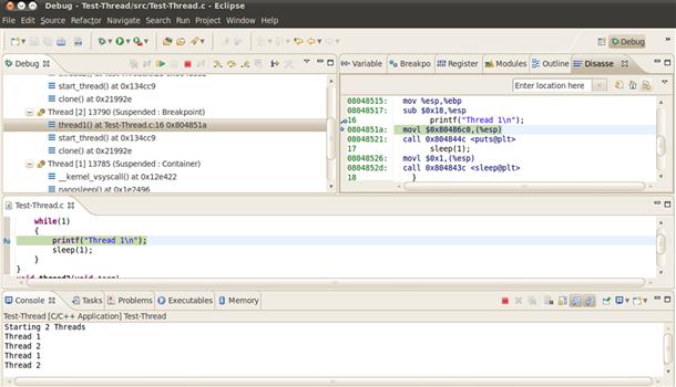
FIGURE 8.6 Eclipse Debugger.
One advantage of using Linux on your embedded target platform is that you can start to develop and debug your application on a host-based Linux system such as on a Linux desktop. In this case, you can use any of the native development and debug tools mentioned above. Once you have completed debugging on the host, you can then migrate your application to the target. If the embedded target system is high performance and provides a display, then you can continue to use a host debugger on the target, but in many cases this is not available. So you must debug the target from the host platform - this is known as cross-debugging. The debugger runs on the host system and communicates with the target either via a direct connection to the processor via JTAG/BDM (background debug mode, or over a communications port such as Ethernet or a serial port (see Figure 8.7).
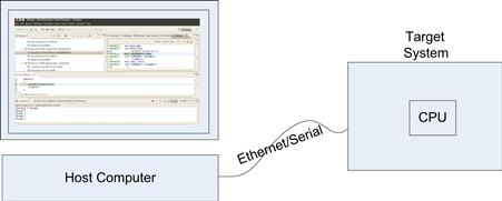
FIGURE 8.7 Cross-Target Debugging.
The target must provide a target debugger agent. In the case of hardware-based JTAG debuggers (see Chapter 17), this agent is provided by the hardware debugger. In software-only-based target debug scenarios, the target debug agent runs on the target CPU.
Kernel Debugging
The most common way of debugging a kernel is to insert strategically placed printk() messages in the kernel and device driver modules. The printk function is an implementation of printf that can be used in the kernel. printk messages are directed to the kernel debug buffer (circular) and the messages are also displayed on the console port. The Linux command dmesg can be used to dump the contents of the kernel debug buffer.
If the kernel crashes, you will be presented with a kernel oops. This is a detailed traceback of the kernel stack; it often provides sufficient information to identify why the kernel crashed, but it can take a significant level of experience to do so. Some systems can be set up to create a core dump file for the entire system (using Kdump). A core dump file contains a complete snapshot of system memory, and all relevant processor state such as register contents. The core dump file can be loaded into gdb and the system memory can be examined in detail. This can make it easier to debug a system crash, but in many embedded systems there is not sufficient local storage to save the core dump file, and relying on a mechanism (eg network stack) to send a core dump file to another system during a crash can be challenging.
Using a debugger to perform host kernel debugging brings about its own challenges. You cannot actively debug on the kernel that you are running on. Specifically, you can’t modify data structures, call functions in the kernel, or use breakpoints. You can inspect the system at great length, and that can often be enough to find the issue. In order to debug any kernel you must edit the kernel configuration to compile the kernel with debugging information (turn on CONFIG_DEBUG_INFO). If you want to inspect the kernel for the host platform you are running on you can issue the gdb command >gdb vmlinux /proc/kcore (on the system you want to debug). This will connect gdb to the currently executing system. The symbols for the kernel are loaded from the vmlinux file (stored in the /boot folder). The /proc/kcore is a special driver used to communicate with the kernel debug agent from the user space gdb application.
Cross-target kernel debugging is likely to be one of the most advanced embedded debugging techniques you will have to master. The core debugger runs on your host development system. The target will require a debug agent to communicate with the debugger on the host system. In many embedded systems you will use some form of hardware probe (via JTAG or BDM). This works well at the start of a system development but is often not practical when you are getting close to releasing the system (production hardware often removes the hardware connectors needed to connect to the hardware probe to save costs). Once the system is stable enough to provide a robust data connection via Ethernet, serial ports, or even USB, a good option is to switch to a software-based target debug agent. Support for remote kernel debugging was introduced (merged) into the 2.6.35 version of the Linux kernel (prior to that it was available as a patch to the kernel). This allows for kernel target debugging.
Another powerful way to debug the kernel is to use a software emulator. An emulator consists of both a CPU emulator and a platform/board level emulation capability. The open source QEMU emulator is a very powerful platform-level emulator. It supports a wide range of CPU architectures along with a number of emulated boards. You can start up the emulator with a debug connection from GBD to a target kernel debug agent running in the kernel, which itself is running in QEMU. In this configuration you can perform kernel level debug of the kernel executing within the QEMU emulator. The only downside is that you are not able to easily debug your target hardware drivers. Having said that, if the hardware being developed is new also, it can be very useful to develop a model of the new hardware in a software environment. You could do this by looking at how devices are emulated in QEMU and create your own device model. Special modeling languages exist such as System-C, these languages can be used to develop functional simulation models. These models can be developed in advance of the actual hardware development, and can be used to develop software while the silicon/hardware is still under development. This can often accelerate the time to market by allowing you to have the software ready when the hardware/SOC is ready. Full platform-level modeling/emulation environments are also commercially available, such as Wind River Simics and Synopsis Innovator.
QEMU Kernel Debugging
QEMU supports a mechanism to connect GDB directly to the simulator. You must first start QEMU in a suspended state, with a GDB server started listening for communications from the debugger. This is a very similar process to debugging any target, except the target is an emulated instance on your host machine. As part of the Linux build, you should have a vmlinux file in the root directory, as we mentioned—you need to build the kernel with debugging options turned on, and this includes all the debug information in the image to allow source-level debug. When the debugger first connects to QEMU, the processor has not even started to execute its BIOS code; the debugger only has symbol information for the Linux kernel.
Build the kernel as described above, including an initramfs.
qemu --gdb tcp::1234 -S -kernel arch/IA-32/boot/bzImage
This starts QEMU in a suspended mode, with a GDB server waiting on TCP port 1234. Add an option to add a file system device/image to QEMU if needed.
ddd ./vmlinux
Load symbol information from vmlinux .
In ddd command window:
target remote localhost:1234
b kernel_start
cont
The commands above connect to the debug server in QEMU, set a break point at the function kernel_start, and runs to that point. Another interesting break point is kernel_init.
You can set breakpoints in the kernel and step through the boot sequence. You can test any code you have placed into a kernel using this simple technique. This mechanism works well when all of the code you wish to test has been linked into the kernel, it is a little more challenging to debug dynamically loaded modules, as modules are dynamically linked to the kernel the debugger does not have an accurate symbol table for the loaded modules.
Driver Development
Device drivers are software components within the kernel that directly interact with a hardware device. They provide a software interface to allow other software components in the system to interact with the device. A device driver performs the following functions:
• Abstracts the hardware. A device driver should abstract the underlying implementations of the hardware. For example, a UART device driver should provide a consistent software interface regardless of the actual physical device specifications.
• Manages privilege. A driver allows an unprivileged application to interface with a device. Traditionally, the code required to manage the driver runs with kernel privileges. However, the application does not need to operate in kernel mode to make use of a device.
• Enables multiplexed access. In many cases a number of applications may require concurrent access to a particular device. The device driver provides mechanisms for multiple applications to use a device concurrently. This may be achieved by serializing access to the device or by merging requests from multiple driver instances to the hardware.
• Martials data to and from an application’s process space to kernel space. A device driver will usually copy data to and from the applications process space into kernel space; kernel memory space is then accessible by the device via DMA.
• Provides security. A device driver may provide security features to prevent an unauthorized process from accessing a device. This capability is usually supported by the operating system.
For Linux, the vast majority of device drivers run in the context of the kernel. As described in Chapter 7, many device drivers provide services to other components in the operating system such as the TCP/IP stack or the file system drivers. In this chapter we describe a driver that provides services directly to user space applications. The device driver provides methods that can be accessed through the /dev pseudo file system and controlled using standard system calls such as OPEN/CLOSE/READ/WRITE and IOCTL. These types of drivers are called character drivers in Linux. This driver type can be used to control simple hardware and demonstrate many of the principles used on more advanced device drivers.
The vast majority of device drivers are written to execute in the kernel and are either statically linked or dynamically linked into the kernel (inserted as modules). In some cases, however, user space drivers are developed. User space drivers still rely on a helper kernel driver, but the majority of the logic is run in user space. Running more code in user space has the advantage of being more robust—an error in a user space driver is not likely to crash the system. However, errors in kernel drivers will almost undoubtedly cause a kernel oops. There are a number of disadvantages, too. The application often requires privileges, as it must map the device memory into user space. Performance is often lower due to process switches needed to access the device. At the time of writing, the XServer is still used extensively. The XServer is one of the most well-known user space drivers, and its successor, Wayland, also relies on applications using user space drivers to render content managed by Wayland.
Character Driver Model
This section provides an overview of the different aspects of a character-based device driver, discusses the user space interface provided by the driver, and the data path from submission of data by the user space application down to an underlying device.
Character Driver—User Space
In order to interact with the device from a user space application, a mechanism is needed to identify the device and subsequently interact with the device. Character device drivers are referenced through special files in the file system. The files are typically in the /dev folder. You can see the files by executing ls -l.
root@ubuntu:/dev# ls -l
total 0
..
crw------- 1 root root 5, 1 2011-05-14 20:31 console
crw-rw-rw- 1 root tty 5, 0 2011-06-02 07:13 tty
crw--w---- 1 root root 4, 0 2011-05-14 20:31 tty0
crw------- 1 root root 4, 1 2011-05-14 20:31 tty1
The c in the ls listing above indicates that the file is a char device. The listing shows two numbers associated with each character file (5,1; 5,0; 4,0; 4,1). These are known as the device major and minor numbers, respectively. The major number typically indicates a device driver type, and the minor number can be used to indicate an instance of the driver. For example, above you can see two tty (terminal teletype) instances.
The major and minor device numbers can be allocated statically or dynamically. The kernel supports a mechanism to allocate such numbers on demand when the driver is initialized. However, the pseudo-character driver in the file system must correlate with these dynamically allocated entries, so you must create the special file after the driver has been initialized. For embedded systems, it is more common to use statically assigned numbers because they are incorporated into the initial RAM file system. The official registry of allocate device numbers can be found in http://www.lanana.org. You should request an allocation if you plan on up streaming your device driver. Major device number 42 is left for demos/prototyping.
The user space application can perform the traditional open/close/read/write and ioctl calls to interact with the device. For example, to open the device, use the following code sequence.
int fd;
fd = open("/dev/tty", O_RDWR | O_SYNC );
if ( fd <= 0 ) {
perror("Error failed open");
}
The function returns a file descriptor (fd), which is then used as an argument for the other functions. The O_SYNC argument is an important option to consider when operating with devices. It indicates that the user space application will block until the data written to the device have been actually written to the hardware.
Note
Deciding between a synchronous and an asynchronous device driver is an important choice to make. A synchronous driver may block the calling application or thread until the data have been written to the device. A nonblocking or asynchronous driver will quickly copy the data from the calling application and let the calling application continue. The driver will write the data to the underlying hardware device asynchronously to the caller. If the data cannot be transmitted for some reason later the caller will not be notified.
Once you have opened the device, you can use the other calls to interact with the device. The following are the most common functions to use.
• read()—This function can be used to read data from the device.
• write()—Conversely, this function is used to write data to the device.
• ioctl()—This is a generic control function that can be used to pass setup information and configuration information to a device.
When the user space library functions are called, the kernel infrastructure directly triggers a call to the associated driver functions.
Character Driver—Kernel Module
This section shows how to create a simple character-based loadable device driver. Writing a sophisticated device driver is beyond the scope of this book; the book Linux Device Drivers is recommended when you are developing a more sophisticated driver (http://lwn.net/Kernel/LDD3/).
The first element is to create a simple make file. There is a standardized make file pattern that can be used to allow you to build a kernel module. You need to download kernel source code in order to build a kernel module; this is to allow you to reuse the kernel make file structure and use the appropriate header files. This kernel must also be compiled, so follow the kernel build steps mentioned above. A module must be compiled against the correct kernel version; that is, the versions must match. If you plan on testing a module on your desktop system, then you must ensure that you download the code for the kernel running on your system. You can find the version by running uname –a. Alternately, use a package manager such as Synaptic Package Manager to download the kernel source for your running system. Aligning the version of the running kernel and the source code used to build a kernel module is critically important; failing to get it right will lead to a frustrating error, “Invalid module format,” when you try to install the module.
In the directory where you are creating the test module, create a make file with the following entry, assuming our module c file will be called ex_kernel_drv.c:
#
# Makefile for simple driver.
#
obj-m += ex_kernel_drv.o
Now create the actual kernel module source, shown in the following. It is a basic character device driver. The driver allows a user space program to write a string to a kernel static buffer and read back from later.
1 #include <linux/module.h>
2 #include <linux/moduleparam.h>
3 #include <linux/init.h>
4 #include <linux/kernel.h>
5 #include <linux/fs.h>
6 #include <linux/errno.h>
7 #include <asm/uaccess.h>
Lines 1–7: The header file required for a simple character device loadable kernel module.
8 MODULE_LICENSE("Dual BSD/GPL");
Line 8: A number of MODULE_∗ definitions are useful in declaring attributes associated with the module. This declares the license under which the module is being released.
9
10
11 #define MAJOR_DEVICE_NUMBER 42
12 char ∗kernel_data;
13 int ret_count;
Lines 11–13: Define the major device number for the driver and allocate a global pointer for the kernel data string that will be updated from user space.
14
15 int drv_open(struct inode ∗inode,struct file ∗filep)
16 {
17 printk("Example driver open ");
18 ret_count = 0;
19 return 0;
20 }
21 int drv_close(struct inode ∗inode,struct file ∗filep)
22 {
23 printk("Example driver close ");
24 return 0;
25 }
Lines 14–25: No specific data are kept when the device is open or closed. No file pointer data are kept (to simplify the example).
26 ssize_t drv_read(struct file ∗filep,char ∗user_buf,
27 size_t count,loff_t ∗offp )
28 {
29 printk("Example driver read: size:%d ",count);
30 if ( ret_count >= strlen(kernel_data))
31 {
32 printk("Example driver read: ret_count = %d",
33 ret_count);
34 return 0;
35 }
36 if (
37 copy_to_user(user_buf,kernel_data,strlen(kernel_data))
38 != 0 )
39 printk("Kernel to user copy failed ");
40 ret_count += strlen(kernel_data);
41 return (strlen(kernel_data));
42 }
Lines 26–42: This is the device function called when the device is read. The key item is the copy_to_user() call. This will copy the data from the kernel data buffer into the buffer provided by the user space read() call. The code managing ret_count ensures that the read call is terminated. The user space application will continue to read from the device until zero characters are returned.
43 ssize_t drv_write(struct file ∗filep,
44 const char ∗user_buf,
45 size_t count,loff_t ∗offp )
46 {
47 printk("Example driver write:Count:%d ",count);
48 if ( copy_from_user(kernel_data,user_buf,count) != 0 )
49 printk("User to kernel copy failed ");
50 ∗(kernel_data+count)=NULL;
51 return count;
Lines 43–52: This is the device function called when the device is written to. The copy_from_user() call copies data from the user space buffer into the kernel buffer.
53
54 /∗
55 ∗ The device operations structure.
56 ∗/
57 static struct file_operations drv_ops = {
58 .owner = THIS_MODULE,
59 .open = drv_open,
60 .read = drv_read,
61 .write = drv_write,
62 .release = drv_close,
63 /∗ .ioctl = drv_ioctl ∗/
64 };
65
66
67 static int __init example_drv_init(void)
68 {
69 printk("Example driver init ");
70 kernel_data = kmalloc(132,GFP_KERNEL);
71 strcpy(kernel_data,
72 "Kernel data string not yet written to ");
73 if ( register_chrdev(
74 MAJOR_DEVICE_NUMBER,
75 "example_dev",
76 &drv_ops))
77 printk("Device registration failed");
78 printk("Example driver init complete ");
79 return 0;
80 }
Lines 53–80: The struct file_operations drv_ops data structure is populated with the function pointers for each operation supported by the driver. The structure contains quite a few more members, but only the members supported by the driver are set up. The format used is an extension to GCC that allows you to initialize a member by name; you do not have to be aware of the member order in the structure. The structure is defined in <linux/fs.h>. Once the structure has been initialized, it must be registered by calling register_chrdev(). The function takes the major device number and the file operations structure.
There is an IOCTL handler (commented on above); an implementation is not shown in this code snippet, but it is very useful to send control information.
81
82 static void __exit example_drv_exit(void)
83 {
84 printk("Example driver exit ");
85 unregister_chrdev(MAJOR_DEVICE_NUMBER,
86 "example_device");
87 kfree(kernel_data);
Lines 81–88: Disconnect this driver from the major number. Free kernel memory allocated in init. This is called when the module is removed via the command rmmod.
89
90 module_init(example_drv_init);
91 module_exit(example_drv_exit);
92
93
Lines 89–93: These functions register the entry and exit points of the module. The function registered via module_init() is called when a module is installed, for example, via the insmod command. Similarly, the function registered via module_exit is the function called when the module is removed via the rmmod command. When we build and run we get the following input and output.
First, we compile the kernel module.
Next, create the device node in the /dev file system.
Now, we load the kernel module (you can verify it was loaded by issuing the lsmod command).
Perform a number of reads and writes to the device.
Kernel data string not yet written to.
Hello world driver.
New string.
Debug messages from the module can be displayed using:
The character driver above demonstrates the simplest interaction model; it does not deal with any real hardware. It primarily shows an example of user space interactions with a driver module.
PCI Device Drivers
The current IA-32-based drivers present the vast majority of hardware as PCI devices. The device may be internal in an SOC or on a board via physical PCIe links, but in all cases they are presented via the logical PCIe discovery model. The kernel identifies all hardware on the system and associates it automatically with the appropriate driver. The kernel uses a combination of PCI Vendor Code and Device ID or Class ID to associate the correct driver with an associated device automatically.
Each kernel module supporting a PCIe device indicates which devices are supported by the device driver. It does so by initializing a pci_device_id table and declaring the structure to the kernel loader using the MODULE_DEVICE_TABLE() macro. A sample from an Intel Gigabit Ethernet driver – e1000_main.c is shown below.
static DEFINE_PCI_DEVICE_TABLE(e1000_pci_tbl)
= {
PCI_DEVICE(0x8086, 0x1000),
PCI_DEVICE(0x8086, 0x1000),
{0,}
};
MODULE_DEVICE_TABLE(pci, e1000_pci_tbl);
In the initiation function you must register the drive handling functions. This is similar to the procedure shown for the simple character device.
static struct pci_driver e1000_driver = {
.name = e1000_driver_name,
.id_table = e1000_pci_tbl,
.probe = e1000_probe,
.remove = __devexit_p(e1000_remove),
#ifdef CONFIG_PM
/∗ Power Managment Hooks ∗/
.suspend = e1000_suspend,
.resume = e1000_resume,
#endif
.shutdown = e1000_shutdown,
.err_handler = &e1000_err_handler
};
pci_register_driver(&e1000_driver);
The probe function is particular to the PCI discovery process. The driver probe function is called with a pointer to the PCI device structure. This provides all the required information for the driver to identify the individual instance of a PCI device being initialized (for instance, there could be many NIC interfaces in the system):
static int __devinit
e1000_probe(struct pci_dev ∗pdev,
const struct pci_device_id ∗ent)
The probe, shutdown, and power manage handlers do not expose any specific capability of the PCI device. It could be a video capture card or a network interface, and these functions would be very similar in behavior. The following are the general steps required during this phase:
1. Enable the device. This can be done by writing to register in the configuration space. The function pci_enable_device() should be called. This ensures that the device is active, allocates memory, and assigns an interrupt if the BIOS/firmware has not done so yet.
2. Request memory-mapped I/O regions for use by the device. This is done using pci_request_regions(pdev, DRV_NAME);.
3. Set the DMA mask size (for both coherent and streaming DMA). This is accomplished using pci_dma_set_mask() and pci_set_consistent_dma_mask(). These calls inform the system about the bus mastering capabilities of the device.
4. Allocate and initialize shared control data. This is shared physical memory that can be accessed by the kernel driver and the device itself. This is usually used for driver control structures such as DMA descriptor. More detail can be found in the kernel/docs/DMA-API.txt. The function -pci_allocate_coherent() is primarily used.
5. Access device configuration space (if needed).
6. Manage the allocation of MSI/MSIx interrupt vectors for the device.
7. Initialize the non-PCI capabilities of the device. These are specific to the device, for example, an NIC or video capture device.
8. Register with other kernel sub systems like the TCP/IP stack and the file system.
9. Enable the device for processing. This usually involves clearing pending interrupts, populating the device descriptors with buffers, and enabling the device and associated interrupts.
These steps ensure that resources are allocated and the device is set up ready to be used.
Network Driver Specifics
In addition to the generic PCI handling and registration mentioned above, each device driver must register its services with the appropriate higher level service in the kernel. In the case of networking drivers, the driver must register functions to allow the TCP/IP networking stack to interact with the adaptor to transmit and receive packets. Again, a standard kernel design pattern is in use here, the pattern is to initialize a structure populated with pointers to functions and then register the structure with the appropriate service. In the case of an Ethernet driver (e1000) the following code snippet shows the registration of the functions to be used by the network stack.
static const struct net_device_ops e1000_netdev_ops = {
.ndo_open = e1000_open,
.ndo_stop = e1000_close,
.ndo_start_xmit = e1000_xmit_frame,
.ndo_get_stats = e1000_get_stats,
.ndo_set_rx_mode = e1000_set_rx_mode,
.ndo_set_mac_address = e1000_set_mac,
.ndo_tx_timeout = e1000_tx_timeout,
.ndo_change_mtu = e1000_change_mtu,
.ndo_do_ioctl = e1000_ioctl,
.ndo_validate_addr = eth_validate_addr,
#ifdef CONFIG_NET_POLL_CONTROLLER
.ndo_poll_controller = e1000_netpoll,
#endif
};
struct net_device ∗netdev;
SET_NETDEV_DEV(netdev, &pdev->dev);
pci_set_drvdata(pdev, netdev);
netdev->netdev_ops = &e1000_netdev_ops;
register_netdev(netdev);
Once the device has been registered via register_netdev(), the networking stack makes calls to the appropriate functions.
Interrupt Handling
Almost all device interactions require that the device driver operate with device interrupts. Interrupts are used to indicate that a change has occurred in the device. The driver is expected to service the hardware interrupt in a timely fashion.
The operating system provides a specific mechanism to allocate and assign a callback function to device interrupts. In IA-32-based systems, many hardware devices are presented as PCIe devices (both on the SOC and external). For such devices, three different types of interrupts support mechanisms in the hardware and are supported by the kernel. They are:
• Legacy Interrupts, often called INTA/INTB/INTC/INTD. These are wire-based interrupts. Each wire is usually shared between multiple devices, and each device can only generate a single interrupt type—sub-interrupts within the devices must be identified by reading an interrupt reason register in the device. This interrupt mechanism should be avoided if possible, primarily due to time spent establishing the true cause of the interrupt. In fact, a device driver using legacy interrupts and supports DMA must perform a read to the device to ensure that all data from the device have been updated in memory before the driver uses the DMA data. This interrupt is also considered to be level sensitive, so you must generally clear the interrupt source in the device at the start of your interrupt handler.
• Message Signal Interrupts (MSI). These allow the system to allocate a number of interrupt vectors to the device. The vectors must be contiguous. When a device generates interrupts, it can generate a specific vector to indicate a specific event in the device. For example, a specific interrupt vector can be triggered to indicate that the device has received a packet, and a separate vector to indicate less critical maintenance events such as an Ethernet link going down. This allows the driver to efficiently handle the underlying event. The MSI message is a special system message that is directed to the CPU’s local Advanced Peripheral Interrupt Controller (APIC). In a multicore system, this can be directed to a specific core. All device MSI vectors must be targeted at the same core.
• Message Signal Interrupts eXtension (MSIx). This is an extension of MSI in that the vectors assigned to a device do not need be contiguous. Additionally, each vector allocated can be directed to a targeted core. With multi core systems, this capability allows you to affinitize interrupts for different devices (or functions within a device) to individual cores, this can greatly improve performance across the system.
The driver should enable MSI/MSIx for a device by calling pci_enable_msi() or pci_enable_msix(). This allocates CPU interrupt vectors and writes the vector data into a PCI device. The interrupt vectors allocated to the device are returned by the call. If the call fails, then the driver should revert to a legacy interrupt support and bind a single interrupt callback function to the legacy interrupt vector. For MSI/MSIx vectors, you should not assume that you obtained all the vectors that the device is capable of generating; the operating system may allocate fewer vectors (perhaps only 1) to a device if vectors are scarce (255 vectors in all). This is not very likely in an embedded system, but you must ensure that your driver handles such cases gracefully.
MSI/MSIx-based systems also follow different ordering semantics for transactions from the device (to devices which use legacy wired interrupts). When a device which uses MSI/MSIx interrupts writes to system memory and then generates an interrupt, the system memory is guaranteed to be up to date when the processor reads the data based on the arrival of the interrupt. The driver is not required to perform a device read to ensure memory consistency.
Once the system allocates the vectors, the driver can assign the vectors to callback routines.
request_irq(IRQ Number,
callback function handler,
irq_flags,
name, /∗ show in statistics ∗/
data);
When an interrupt fires on the device, the callback function handler is called with an interrupt vector and a void∗ data pointer. The data pointer is usually set to a device driver stricture that contains all the required device instance/specific information (including a pointer to the PCI device structure for the device.). The interrupts statistics can be seen in the /proc/interrupts pseudo file system.
The handler runs in interrupt context. In most systems, there are significant limitations to the operating system functions that can be called from interrupt context. The in_interrupt() call returns true if the calling function is in the interrupt context, this call can be used to check the calling context and ensure the function does not call inappropriate services given the calling context.
The amount of work performed in the interrupt handler should be kept to a minimum; specifically, only perform the time-critical aspect of servicing the device. At a minimum, the interrupt handler runs with the current interrupt level disabled, so running too much code may affect the performance of other critical interrupt handling, specifically it can add to the jitter associated with processing other key interrupts.
All other work related to the device should be deferred in an alternative non-interrupt context. Operating systems provide a specific mechanism to defer work to a kernel task context to perform the remainder of the work. In Linux these are kernel bottom halves/tasklets, while on VxWorks you can transfer work to any system task.
Deferred Work
Three key capabilities in the kernel can be used to defer work from the interrupt handler, namely, softIRQs, tasklets, and work queues. Deferred work occurs with interrupts re-enabled and are scheduled by the operating system at a convenient time. They are often run directly after the return from the interrupt handler—the key difference being that interrupts have been re-enabled. The term bottom-half handling is often used to refer to this deferred work.
softIRQs. There are 32 softIRQs defined in the system. They can run concurrently in the system (in a multiprocessor system) and are statically configured at compile time in the kernel/include/linux/interrupt.h/ file. They cannot be created dynamically. In fact, you have to modify the kernel to add to the list, so it is not really feasible for you to add them unless you are working with upstream kernel maintainers. The softIRQs form the base for other deferred work mechanisms such as tasklets. Because of the static nature of softIRQs they are not generally directly used by device drivers. There are 10 of the 32 softIRQs that are used at the time of writing. Two of the softIRQs are dedicated to the execution of tasklets (one high-priority list and one low-priority task list).
Tasklets. Tasklets are functions that are run from the context of the softIRQ. A tasklet is a function that is added to a linked list and then called when the softIRQ executes. Only one instance of a given tasklet is guaranteed to execute at any one time. Even on multicore systems, the tasklets will be serialized to ensure that they do not run concurrently. This has the advantage that you do not have to worry about locking data structures used within a tasklet on a multicore system. Tasklets are the best way to defer work from the interrupt handler (with the exception of network device drivers). Tasklets must run to completion and should not block. If the tasklet blocked, it would prevent/delay the execution of other tasklets.
Work Queues. Work queues are the final mechanism we can use to defer work. Work queue items are executed in the context of a kernel thread. The kernel thread associated with the work queue runs as a process that is scheduled. As it runs in the context of a kernel thread, it can make use of all standard kernel services, block on semaphores, allocate memory (which may not be immediately available), and sleep to poll hardware. Generally speaking, a work queue should be used if such services are required.
Note
Network device drivers defer work using the napi_schedule(). The napi_schedule() function is implemented in linux/net/core/dev.c. The call uses the NET_RX_SOFTIRQ softIRQ to defer network device driver–related work.
Interrupt Flow Summary
The pattern of handling interrupts in Linux is a general design pattern for handling interrupts in many embedded systems. The objective is to balance the needs of low latency interrupt service requirements of the hardware while ensuring that the overall operation of threads/tasks in the system is also accommodated. It should be noted, however, that in some special embedded cases, all of the required interrupt handling is performed in interrupt context; this is where there are very tight temporal bounds to service the hardware. However, such handlers can have adverse effects on the rest of the system unless they are well understood. Figure 8.8 shows an example of flow from hardware interrupt to user space task execution.
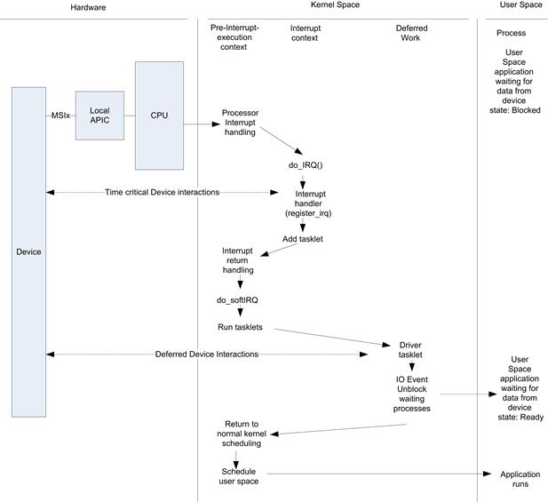
FIGURE 8.8 Interrupt Flow through Linux.
Careful attention must be paid to interrupt processing in embedded systems. You have to consider what other interrupts in the system may delay the execution of critical interrupts associated with any real-time behavior.
Memory Management
There are two distinct memory allocation domains within Linux. This section touches upon the allocation of memory for user space application, kernel space allocations, and mechanisms to share memory between user and kernel space.
User Space
The most well-known mechanism for requesting memory from user space is to call malloc(). This is a C library function that returns a user space pointer to the allocated memory. The pointer contains a virtual address, and the MMU system within the CPU translates access to this virtual address to an underlying physical memory location(s). The memory is contiguous as far as the user space application is concerned, however the allocation may have come from multiple physically discontinuous memory pages. The MMU tables are appropriately configured to ensure the contiguous virtual address mappings.
An important attribute to this memory is that it is subject to paging to disk if the system becomes oversubscribed (in terms of memory requests). You should note that paging is generally turned off in embedded systems due to file system wear (particularly for flash devices) and nondeterministic performance. The user space memory library often makes requests to the underlying kernel for memory.
Access to User Space memory from the Kernel
When a user space application makes a system call such as write() to a device, a transition from user space to kernel space occurs. The appropriate device driver write function is called (as in the case of our character driver above). The write function will be working on behalf of the calling user space process and as a result is said to be running in its process context. While in process context, the memory of the calling process and kernel mappings are accessible (provided no paging has occurred). In this context both the user space process and kernel virtual address ranges are available, as a result the virtual address assigned to the kernel and those assigned to processes must be unique. In a 32-bit Linux system, processes are assigned virtual addresses that range from zero to 3 GBytes, and the kernel uses virtual addresses that ranges from 3 GB through 4 GB. The Linux system calls copy_from_user() and copy_to_user() are provided to copy data between the user space pages and the kernel pages.
Function
copy_from_user()– Copy a block of data from user space.
Arguments
to – Destination address, in kernel space.
from – Source address, in user space.
n – Number of bytes to copy.
Context
User context only. This function may sleep.
Description
Copy data from user space to kernel space.
Figure 8.9 shows the mapping and copy. If the user space memory has been paged out, the process context is blocked until the page has been brought back into physical memory.
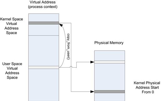
FIGURE 8.9 The copy_from_user() Function.
Kernel Allocation
The kernel manages all memory in physical page units. Each processor has a defined page size (4 K on IA-32). The kernel tracks every page in the system with page structure defined in linux/include/linux/mm_types.h.
The following key attributes are maintained for each physical page in the system:
• Page flags. If the page is dirty, referenced, locked, backed by a swap copy, least recently used data. The flags are found in linux/include/linux/page-flags.h.
• Virtual address. Usually the virtual address of the page. This is valid for most of the memory in the system. However, there are cases where a physical memory location is not always mapped to the kernel, as in the case of what is known as HIGHMEM. HIGHMEM memory has a null address in the page mapping.
• Owner. The kernel must track available pages, particularly if they are to support allocation of such pages.
Information on the current page statistics can be found using the command >cat /proc/meminfo.
The kernel supports a number of different logical zones for memory allocation. The zones address ranges are processor architecture specific. The first is ZONE_DMA; when an allocation request ZONE_DMA is requested it provides pages that are guaranteed to be accessible by any DMA agent in the system. In some cases devices with DMA capability are not all capable of accessing all addresses in the system. This is set to <16 MB in IA-32 systems to cover old ISA bus devices and is rarely used at this point. ZONE_DMA2 is a zone that is supported on IA-32 systems. It is used for devices that can only access 32-bit address space but with more than 4 GB of memory populated (x64).
ZONE_NORMAL is the normal memory zone used. If used with a device, the device must be able to access all system memory (for a 32-bit device system, all 4 GB must be accessible from the device). Memory obtained from this zone has a valid virtual address that can be used to dereference the physical memory at any time. Most allocations use this zone. It’s important to note that there is a fixed offset between the virtual address and physical address allocated from the normal zone. This is very important; in many cases device drivers convert from virtual addresses to physical (and then bus address) addresses when interacting with a device. It is important for the cost of such translations to be low, and having a fixed arithmetic offset between the two addresses achieves a very efficient translation at runtime. The function virt_to_phy() performs such a translation.
ZONE_HIGH_MEM is assigned to pages that are high in physical memory (above 900 MB). As mentioned earlier, the kernel occupies virtual address ranges from 3 GB through 4 GB. That is, it is allocated 1 GB of virtual address. Therefore, it cannot have all physical addresses mapped. In this case you can still allocate the pages, but there is no permanent virtual mapping to the physical page. These pages must be mapped if you need to read/write the memory from the kernel at run time. However these memory regions are accessible from devices via DMA without creating a kernel virtual address mapping.
Page Allocation
A number of low-level functions can be used to request memory from a particular zone. The allocations return memory that is both page-aligned and with page granularity. The lowest level page allocation function is
struct page ∗alloc_pages(unsigned int gfp_mask,
unsigned int order)
This function allocates 2 << order contiguous pages from the kernel. The function returns a page structure. The flags include the ZONE and other elements described later. The virtual address mapped to the page (for DMA_ZONE and DMA_NORMAL) can be obtained from the returned page structure by calling page_address(). As the physical pages must be contiguous (not the case for user space malloced memory). It is often difficult to obtain large contiguous memory regions from the kernel, especially the longer the system is up and running. In most cases you should request your large contiguous memory requests during startup to improve the likelihood of success, however in general it is better to assume you cannot guarantee large physically contiguous memory allocations. As a general rule of thumb, a 64-kB block is considered a large contiguous section to request. When large contiguous memory regions are needed, you can make a call to alloc_bootmem() during system startup. This has a much higher probability of succeeding, and it is used when very large buffers are needed (several megabytes).
In many cases, device drivers make use of linked lists of pages to describe incoming and outgoing data. These are arranged as linked lists of pages; each page is contiguous but the list does not need to be made up from contiguous pages. These lists are referred to as scatter gather lists. Corresponding to the DMA engines, a device should support a descriptor mechanism whereby a logical contiguous data block can be characterized by a list of physical pointers.
The kmalloc() Function
The kernel provides a function very similar to the user space counterpart malloc(). The page allocation routines above may be very inefficient if small allocations (below one page) are required. The kernel maintains a SLAB of buffers and can efficiently provide subpage or page size allocation.
Void ∗ptr;
ptr = kmalloc(1024,GFP_KERNEL);
..
kfree(ptr);
The kmalloc function returns at least the number of bytes requested, but they are not necessarily page aligned (often important for devices). The second argument is the gfp_mask flag. The flags are defined in linux/include/linux/gfp.h and slab.h. The mask can be broken down into two separate modifiers.
• Zone modifiers. These are __GFP_DMA, __GFP_NORMAL, and __GFP_HIGHMEM. You cannot use the HIGHMEM zone with calls that return a mapped virtually address such as kmalloc. In practically all cases the NORMAL zone is used.
• Action modifiers. These control the behavior of an allocation, such as whether the request can sleep waiting for memory to be available, or if the allocator can return with a failed request.
Luckily, the kernel provides a number of predefined definitions that you can use without the need to understand the lower-level details, as shown in Table 8.2.
Table 8.2. Flag Types (Subset).
| Flag | Description |
| GFP_USER | Allocates memory on behalf of a user process (current process context). May sleep. |
| GFP_KERNEL | Allocates normal kernel memory. May sleep. |
| GFP_ATOMIC | Allocation will not sleep, uses emergency pools, and can be called from interrupt handlers. |
| GFP_HIGHUSER | Requests high memory; cannot be used with kmalloc. |
| GFP_NOIO | Does not perform any I/O while trying to get memory. |
| GFP_NOFS | Does not perform file system I/O while trying to get memory. |
| GFP_NOWAIT | The allocation request cannot sleep, but may fail. |
| GFP_THISNODE | In some SMP NUMA vases you may want to allocate memory closest to a particular processor. This makes such a request. |
The majority of uses of kmalloc simply use the GFP_KERNEL flag.
PCI Memory Allocation and Mapping
The PCI subsystem provides a number of memory allocation routines that should be used when allocating memory, which is shared between the processor and a device. There are a wide range of system combinations supported by Linux, 32-bit/64-bit CPU, 32-bit/64-bit PCI, different processor endianness, PCI bus address translation in controllers, memory coherence (between CPU and devices)—all of which lead to challenges in creating platform device drivers for PCI devices that may be used in any system. The expectation of a device driver that has been upstreamed and hosted at kernel.org is that it will operate on any supported architecture if a PCI bus is supported.
A device driver may allocate memory for use as a shared communication area between the processor and device. The device driver must have a virtual address mapping for this memory in order to write to the memory. The device must also be informed of the address in a configuration register. The address written to in the device must be the address the device puts in the PCI transactions and is called the bus address. The driver must have the physical and bus address that corresponds to the virtual address used by the driver. On older kernels this translation was achieved by calling virt_to_bus() and bus_to_virt(). However, these have been superseded by the PCI DMA interface and should not be used.
The DMA API provides allocation for two different use cases, known as consistent and streaming. Consistent mapping should be used for memory that must be guaranteed to be accessible from the device at all times. It is typically allocated and mapped during initialization. The device and CPU can access the memory concurrently. The software is not expected to perform any cache flush (for non-cache coherent architectures) for this memory space. When the CPU writes to this space, it is immediately visible to the device. There are some processor architectures where you need place a write barrier in the instruction pipeline to ensure such consistency. This can be achieved by using the write memory barrier call wmb(). The IA-32 processors are strongly ordered and do not require the wmb(). Processors such as Itanium® are weakly ordered and do require such barriers.
The call to allocate a consistent area of memory uses the following function:
dma_addr_t dma_handle;
cpu_addr =
dma_alloc_coherent(dev, size, &dma_handle, gfp);
The function returns a CPU virtual address that can be directly used by the driver to read from and write to the memory. It also returns a dma_handle. The DMA address is the appropriate bus address that can be written to the device.
The DMA Streaming API provides a mechanism to obtain bus addresses for data. The data could be allocated from the NORMAL or HIGHMEM zones. The functions used are called dma_map_single(), dma_map_page(), and dma_map_sg().
dma_addr_t dma_handle;
dma_handle = dma_map_single(dev, addr, size, direction);
The function returns the bus address for the virtual address provided. The function also performs any architecture-required cache coherence updates. You should consider the data to be “owned” by the device after a map call is made. The reciprocal dma_unmap_single(), dma_unmap_page, dma_unmap_sg() functions should be called once the driver is aware that the device no longer needs access to the mapped page. For example, it may be known that the device interrupts the process to indicate that the packet has been transmitted. The calls take a direction parameter to indicate whether the buffer is going to be written to or read from the device, or both.
Synchronization/Locking
All operating systems provide primitives for synchronization and locking mechanisms to develop race-free code. In this section we cover atomic updates to variables, spinlocks, and semaphores.
Atomic Operations
An atomic operation is an operation that runs without being interrupted. Operations on atomic integers are easy to use.
atomic_t atomic_var;
atomic_set(&atomic_var, 10); / set to 10
atomic_add(5,&atomic_var); // add 5 to the variable
atomic_inc(&atomic_var); // increment by 1.
Atomic intrinsics usually use processor atomic instructions, such as the IA-32 instruction TSL (test set and lock) or Locked CMPXCHG (locked compare and exchange), which are used to build up these underling atomic operations. These instructions can be costly and often serialize the processor’s pipeline.
Atomic operations are often used to update counters, although the use of atomics for simple counters should be avoided where possible (create per CPU/context counter values).
Spinlock
In many cases, a sequence of code needs to run that must be executed in one execution context at any given time. No other context can enter the synchronized area of code until the previous context leaves the synchronized area. A simple example of such a case is to update a linked list where head/tail pointer updates must be carried out atomically.
To facilitate such serialization, the Linux kernel provides spinlocks. A spinlock can only be held/owned by one execution context (thread). If the lock has not yet been acquired, then the first thread to request it obtains the lock (with little overhead). If an execution context attempts to acquire the lock but it has already been acquired, then the calling context will simply spin in a loop until the other context releases the lock. Spinlocks are very fast and efficient in terms of acquisition cost, but the CPU running the busy loop is wasting CPU time until the contended execution context is de-scheduled (in a single-processor system).
spinlock_t link_lock = SPIN_LOCK_UNLOCKED;
spin_lock(&link_lock);
…
spin_unlock(&link_lock)
Obviously, you have to be careful to ensure that you do not create a deadlock scenario, for example, by using spinlocks between an interrupt and kernel thread. To facilitate the use of spinlocks between interrupt and kernel execution context you can use spin_lock_irqsave() and spin_unlock_irqrestore().
Depending on the use case, the use of a generic spinlock may block threads that in reality do not need to be. The most common use case is the single writer, multiple reader design pattern. In this case the kernel provides a lock that does not block multiple readers until a thread wishes to perform an update/write. The read_lock() and write_lock() functions provide such capabilities.
Semaphore
A semaphore is a lock, but it may sleep the context that attempts to obtain a contented lock. Instead of running a busy loop waiting for the lock, the thread is placed in a not-ready state and de-scheduled. Semaphores should only be used where the expected wait time is long; spinlocks should be used in short wait use cases.
The semaphores implemented in the Linux kernel are known as counting semaphores, and the count can be specified. In many cases the count is specified as one, which makes the semaphore a binary semaphore or mutex. There is an API added for mutexes given that they are so common.
static DECLARE_MUTEX(link_mutex);
// attempt to get the semaphore
if ( down_ interruptible(&link_mutex))
{
/∗ only case were we don't get the mutex is due to
reception of a signal.∗/
…handle signal ..
}
/∗ Critical section ∗/
…
/∗ release the mutex ∗/
up(&link_mutex);
Given that semaphores and mutexes may cause the calling context to switch, they thus cannot be used from an interrupt context.
Summary
The Linux system is truly amazing. It supports a tremendous number of processor architectures and devices. The subsystems provide an excellent range of capabilities, such as networking and sophisticated file systems. There is a rich set of user space packages providing sophisticated capabilities such as immersive user interfaces and database functions. The capabilities available match well to almost any embedded class of device. The challenge is specifying and scaling the system to the appropriate footprint required by many resource-constrained embedded platforms.