Chapter 3
Switches, Routers, and VLANs
IN THIS CHAPTER
![]() Considering the value of switches
Considering the value of switches
![]() Understanding how switches do their magic
Understanding how switches do their magic
![]() Examining the role of routers
Examining the role of routers
![]() Getting to know VLANs
Getting to know VLANs
In this chapter, I dig deeper into two of the most basic and ubiquitous networking devices: switches and routers. Every network has at least one switch and one router, and all but the smallest networks have more than one switch. These components are the basic building blocks of networks, so understanding what they do and how they work is essential to properly designing, implementing, and maintaining a network that functions well.
Besides switches and routers, this chapter also introduces the concept of virtual local area networks (VLANs). A VLAN is a fancy technique that lets you split a single physical network into two or more logical networks. VLANs are one of the key techniques for organizing a network in a way that will allow the network to scale up as your organization grows. Small networks don’t need to worry about VLANs, but even in a relatively small network, it pays to know what VLANs are. Introducing VLANs into your network before you actually need them will simplify your life as your network grows.
Understanding Switches
In the previous chapter, I explain that a hub is a layer-1 device that simply repeats all incoming network data to all its output ports. In other words, if a hub has eight ports, any input data that arrives on port 1 will be amplified and repeated on ports 2 through 8. A hub is an unintelligent device — the hub doesn’t know or care what the intended destination of the incoming data is. It simply sends the data to all its ports, hoping that the intended recipient is on one of those ports. (Actually, using the term hope here is misleading, because as I said, the hub not only doesn’t know who the intended recipient is but doesn’t even care. Hubs have no capacity for hope.)
Figure 3-1 shows a simple network with four computers connected via a hub. In this example, Computer 1 is sending data to Computer 4. As the figure shows, the hub doesn’t know that the intended recipient is Computer 3, so it sends the data not just to Computer 3, but also to Computer 2 and Computer 3 as well.
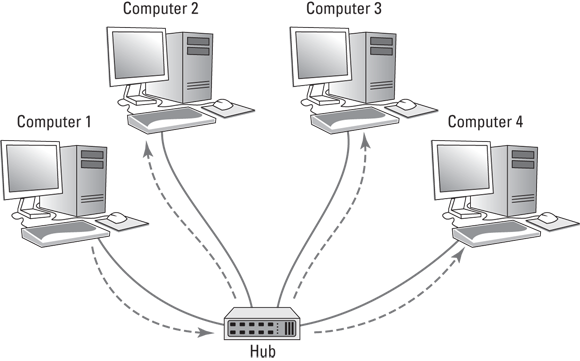
FIGURE 3-1: A hub repeats all incoming data on all its ports.
To understand why hubs even exist, or at least did exist in the distant past, we need a little history lesson. Ethernet was invented in the late 1970s and first became commercially available in 1980. From the very beginning, Ethernet used what is called shared media to connect devices in a network. The basic idea of Ethernet is that data is sent over network cables in the form of packets, which follow a well-defined structure. The key elements of the original Ethernet were (and still are) as follows:
- All devices on the network can access all data sent over the network. That’s why the network cable itself is considered to be shared media.
- Every device on the network has a unique identifier called a MAC address. I cover MAC addresses in the preceding chapter. As a quick reminder, MAC addresses are 48 bits long and are written as six octets separated by hyphens. For example, 21-76-3D-7A-F6-1E is a valid MAC address.
- A data packet includes the MAC address of the packet’s intended recipient, as well as the MAC address of the sender.
Every device on the network receives every packet that is sent on the network and examines the destination MAC address to determine whether the packet is intended for it. If so, the device says, “Mine!” and stores the packet to be processed by other protocols higher up the food chain (that is, at higher levels in the OSI Reference Model). If the destination MAC address doesn’t match the device’s, the device says “Hmph!” and simply ignores the packet.
All the devices on the network do this examination, keeping only the packets that belong to them and ignoring all the others.
- If the destination MAC address is all ones (represented as FF-FF-FF-FF-FF-FF), the packet is called a broadcast packet. When a broadcast packet is sent, every device on the network looks at the destination MAC address, sees that the packet is a broadcast packet, and says, “Mine!” Broadcast packets are received by every device on the network.
- Every once in a while, two devices try to send a packet at the exact same time. When that happens, both packets are garbled. The result is called a collision. When collisions happen, both senders wait for a brief amount of randomly generated time and then try again. The collision probably won’t happen again. But if it does, the senders wait and try again later.
So, that’s a recap of the basic operation of the Ethernet networking system. Because it was a great system when it was invented, it quickly replaced the two dominant network technologies that were popular at the time, ARCNET and token ring. But unfortunately, Ethernet had a few serious problems lurking under the surface that proved to be a problem for larger networks:
- The frequency of collisions rises exponentially with the number of devices added to the network. When you get too many devices, collisions happen all the time, and devices spend way too much time resending packets, sometimes having to resend them over and over again until a collision doesn’t happen. This results in the network becoming much slower as it grows larger.
- The frequency of broadcast packets can quickly increase as more devices are added to the network, further adding to the performance problem and the likelihood of collisions.
- Security is difficult to enforce, because every device on the network must examine every packet that comes its way. Even though devices are supposed to ignore packets that aren’t meant for them, there is no way to ensure that they do so.
Switches to the rescue!
A switch is essentially an intelligent hub that has the ability to actually look at the contents of the packets it processes and make intelligent decisions about what to do with them. A hub is a layer-1 device, which means that it can do nothing but receive and amplify electrical signals. In contrast, switches are layer-2 devices, which means they can actually inspect the layer-2 packets and act intelligently based on the content of each packet.
A switch examines the destination MAC address of every packet it receives and forwards the packet only to the port that leads to the packet’s intended destination. Thus, packets aren’t repeated on ports that don’t contain the packets’ destination.
Figure 3-2 shows the same simple network that was shown in Figure 3-1, but this time with a switch instead of a hub. As you can see, the switch is smart enough to know that the data sent by Computer 1 is intended for Computer 3. So it sends the data only to Computer 3; the switch leaves Computer 2 and Computer 3 alone so they can concentrate on other work.

FIGURE 3-2: Unlike a hub, a switch knows where to send its data.
In order to accomplish intelligent forwarding, a switch must know what devices are connected to each of its ports. In the next section, you see how a switch learns what devices are connected to each of its ports.
Learning
For a switch to do its job, it needs to know what devices are connected to each of its ports. More specifically, the switch needs to know what MAC addresses are reachable via each of its ports. It does this in an ingeniously simple way: It simply learns. Whenever a packet is received on any of the switch’s ports, the switch examines the sending MAC address in the packet. The switch rightly assumes that if it received a packet from a given MAC address on a given port, the switch can reach that MAC address via that port. For example, if a switch receives a packet from Computer C on port 3, the switch has learned that Computer C is reachable on port 3. The switch adds this information to the MAC address table. This table is sometimes referred to as a forwarding database, because it keeps track of which port packets intended for a given destination should be forwarded to. The MAC address table simply keeps a tally of which MAC addresses are reachable on each port of the switch. Suppose the MAC address for Computer C is 21-76-3D-7A-F6-1E. If the switch receives a packet from port 3 with that MAC address, it would add the following entry to the MAC address table:
Port |
MAC Address |
|---|---|
3 |
21-76-3D-7A-F6-1E |
In this way, the switch has learned that Computer C is reachable via port 3.
After a short time, the switch will likely receive packets from all its ports and will associate the sender’s MAC address with each port:
Port |
MAC Address |
|---|---|
1 |
40-20-08-78-84-52 |
2 |
2F-B6-E0-F6-EA-05 |
3 |
21-76-3D-7A-F6-1E |
4 |
63-44-E4-A7-4F-E0 |
5 |
76-2F-F9-C8-B6-08 |
6 |
FC-78-B6-07-52-EA |
7 |
CD-34-E4-B3-2C-76 |
8 |
1C-FD-E0-63-21-C0 |
It’s important to keep in mind that a switch port might actually connect to more than one device. For example, suppose port 5 isn’t connected to a computer but to another switch, which in turn has three other computers connected to it. In that case, the first switch can receive packets from three different computers on port 5. Then, the switch records each distinct MAC address in its MAC address table, something like this:
Port |
MAC Address |
|---|---|
1 |
40-20-08-78-84-52 |
2 |
2F-B6-E0-F6-EA-05 |
3 |
21-76-3D-7A-F6-1E |
4 |
63-44-E4-A7-4F-E0 |
5 |
76-2F-F9-C8-B6-08 |
5 |
D6-4E-69-86-E9-F7 |
5 |
06-C1-15-A2-BA-60 |
6 |
FC-78-B6-07-52-EA |
7 |
CD-34-E4-B3-2C-76 |
8 |
1C-FD-E0-63-21-C0 |
The process of building the MAC address table is called learning, and is one of the three basic functions of a switch. The other two are forwarding and flooding, as described in the next two sections.
Forwarding
Now that you know about the MAC address table, you should have a good idea of how a switch knows which ports to forward incoming packets to: The switch simply looks up the destination MAC address in the table and sends the packet out through the corresponding port.
For example, if the switch receives a packet on port 1 intended for MAC address CD-34-E4-B3-2C-76, the switch looks up that MAC address in the table, finds that the MAC address can be reached on port 7, and forwards the packet out to port 7. This process, called forwarding, is the second basic function of a switch.
Switches have memory buffers associated with each port that allow the switch to store a complete packet before forwarding it to the destination port. This allows the switch to hold onto the packet for a bit if necessary before forwarding it. For example, the destination port may be busy sending out a packet received from a different port. Or, the destination port may be busy receiving a packet. In either case, when the port becomes free, the switch can transmit the packet to its destination.
It’s important to understand that the switch does not modify the packet in any way prior to sending it. What gets sent out to the destination port is an exact replica of what was received on the incoming port. When the destination device receives the packet, the device has no idea that the packet passed through the switch. In other words, no tracing information is added to the packet by the switch.
It’s also important to know that, at least at this level of operation of the switch, the switch has no idea or concern for the contents of the Ethernet frame’s payload. In particular, the switch is not concerned with the possibility that the payload may be an IP packet, which in turn contains an IP address. Switching does not rely on or even know about IP addresses. Switching is a layer-2 function, and layer 2 is concerned with MAC addresses. IP addresses are a layer-3 concern and, thus, are hidden from switches.
 Here’s where I have to tell you that I lied. It isn’t exactly true that switches don’t care about IP addresses. Many advanced switches have layer-3 features that do look at the IP address. But when they do, they’re acting more like routers than switches. Routers work at layer 3 and, therefore, deal with IP addresses. I have more to say about that later in this chapter, in the “Understanding Routers” section.
So, to recap, when a switch receives a packet on one of its ports, the switch looks in the Ethernet frame to determine the destination MAC address. The switch then looks that address up in its MAC address table, determines which port is associated with the destination address, and forwards the packet on to that port.
Which begs the question: What happens if the switch doesn’t recognize the destination MAC address in the forwarding database? The answer is found in the next section.
Flooding
When a switch receives a packet that is intended for a MAC address that isn’t in the switch’s internal MAC address table, the switch has no way to know what port to forward the packet to. In that case, the switch has no option but to revert to acting like a hub: The switch simply forwards the packet on all available ports other than the one the packet arrived on, of course. This is called flooding, which is the third function of a switch (the first two being learning and forwarding).
The packet will be forwarded even to ports for which the switch has already learned a MAC address. This is necessary because a single port can be a pathway to more than one MAC address, as is the case when the port is connected to another switch.
Flooding is similar to broadcasting, but it isn’t quite the same. A broadcast packet is a packet that is intended for every recipient on the network. Thus, a switch must forward broadcast packets to every port. In contrast, flooding results when the packet has a single destination, but the switch doesn’t know how to reach it. Thus, the switch sends the packet to every port in the hopes that one of them will lead to the destination.
Hopefully, flooding doesn’t happen too often. There’s a very good chance that the destination device will receive the packet and send a reply back to the sender. In that case, the switch will record the MAC address of the recipient in its table. Then, the next time a packet intended for that destination is reached, the switch will be able to forward it to the correct port rather than flood the network again.
Looking Deeper into Switches
In the previous sections, you learned about the three basic functions of a switch:
- Learning: The switch learns what devices are reachable on each of its ports.
- Forwarding: The switch forwards incoming packets just to the correct port based on the intended destination.
- Flooding: The switch forwards incoming packets to all ports when it hasn’t yet learned how to reach the intended destination.
In the following sections, I dig deeper into the operation of switches to explain more about how they operate.
Collision domains
One of the main benefits of switches over hubs is that switches minimize the frequency of collisions on the network. Consider a four-port switch in which Computers 1, 2, 3, and 4 are connected to ports 1, 2, 3, and 4. If port 1 receives a packet from Computer 1 that is intended for Computer 2, the switch will forward the packet to port 2. If, at the same time, port 3 receives a packet intended for Computer 4, the switch will forward that packet to port 4. Both of these packets can travel on the network at the same time because at no time will they exist on the same set of network interfaces or cables. Thus, the packets will never collide.
In contrast, if these four computers were connected with a hub, the packets would collide because the two packets would be forwarded to all the ports, not just the ports connected to the destination computers.
This reduction of collisions is so fundamental to what a switch does that a common definition of what a switch is reads like this: A switch is a device that divides collision domains. A collision domain is a segment of a network on which collisions are possible. In an old-style Ethernet network built with hubs, the entire network is a single collision domain because all the network interfaces that connect to the network will see all packets that travel on the network. But when a switch is used, the network is divided into separate collision domains.
In a switched network, each collision domain consists of just two network interfaces: the port on the switch and the port on the destination device (typically a computer, but possibly another switch). An eight-port switch divides a single collision domain with eight devices into eight separate collision domains, each with only two devices.
Switches don’t completely eliminate collisions. For example, suppose a switch has received a packet intended for a computer, and that computer attempts to send a packet at the same moment that the switch attempts to forward the received packet to the computer. In that case, the two packets collide, and both the switch and the computer must wait and try again a bit later.
Bridging
A bridge is a device that is very similar to a switch, but it typically has fewer ports — perhaps as few as two. The primary purpose of a bridge is to provide a link between two networks, so some bridges have just two ports. Like a switch, a bridge examines the destination MAC address of every packet it receives and forwards the packet to the other side of the bridge only if the bridge knows that the destination is on the other side.
Technically speaking, a switch is simply a multiport repeaters bridge. The distinction is mostly a historical one, because bridges were invented and widely used before switches. Before switches became inexpensive, large Ethernet networks used multiple hubs to connect computers and other devices, and a few bridges would be introduced into the network to break up large collision domains. Now that switches are common, you don’t see separate bridging devices much anymore.
However, one function that a bridge can perform can come in handy: A bridge can be used to connect two different types of networks. For example, suppose your main network uses Cat-5e cable, but you also have a smaller network that uses fiber-optic cable. You can use a bridge to link these two types of networks. The bridge would have two ports: One Cat-5e port and one fiber-optic port. When the bridge receives a packet on the Cat-5e port, it forwards it to the fiber-optic port, and vice versa.
All switches can perform this type of bridging to connect Cat-5e devices that operate at different speeds. For example, most computers have network interfaces that operate at 1 gigabit per second (Gbps). But many printers have slower, 100 megabits per second (Mbps) connections. The ports on a switch can automatically detect the speed of the device on the other end of the cable, so you can plug a 1 Gbps computer or a 100 Mbps printer into a switch port. The switch will automatically take care of buffering and forwarding packets received from the 1 Gbps devices to the slower 100 Mbps devices.
Some switches also include ports that allow you to connect the switch to even faster networks that use 10 Gbps copper or fiber-optic cable, as described in the next section.
SFP ports and uplinks
Some switches have special ports called small form-factor pluggable (SFP) ports. You can use an SFP port to connect a variety of different types of high-speed networks, including 10 Gb Ethernet (which uses copper cable) or 8 Gb Fibre Channel, which uses fiber-optic cables. In this way, the SFP ports allow the switch to bridge 100 Mbps or 1 Gbps Cat-5e networks with faster copper or fiber-optic networks.
One of the most common uses of SFP ports is to connect switches to each port at speeds faster than 1 Gbps. The interconnection between two switches is often called an uplink. It makes sense to use high-speed uplinks because the uplink ports are likely to be the busiest ports on the switch. For example, suppose you have a network with 80 computers in which 40 of the computers are connected to one switch (call it Switch A) and the other 40 computers are connected to a second switch (Switch B). If a computer on switch A sends a packet to a computer on Switch B, that packet must travel through the uplink ports to get from Switch A to Switch B. So, you can expect that the uplink ports will carry as much as 40 times the amount of traffic that the other ports carry.
Another common use of SFP is to connect switches to server computers. This also makes sense, because the ports that connect to your servers will carry much more traffic than the ports that connect to workstations. In order to connect a switch to a server using an SFP port, both the switch and the server must have SFP ports. So you’ll need to make sure both your servers and your switches have SFP ports.
Broadcast domains
Earlier in this chapter (in the “Understanding Switches” section), I mention that packets whose destination MAC addresses are all ones (FF-FF-FF-FF-FF-FF) are intended to be received by all devices that see the packet. Such packets are called broadcast packets.
The scope of the devices that broadcast packets are intended for is called the broadcast domain. Ordinarily, a switch forwards broadcast packets to all the ports on the switch except the port on which the broadcast packet was received. Thus, the broadcast domain consists of all the devices connected to the switch, either directly or indirectly through another switch.
In many cases, allowing broadcast packets to travel throughout a large network is not a good idea. If the network is large, broadcast packets may consume a significant amount of the total bandwidth available on the network, slowing down other more important traffic.
You may be surprised to discover just how much broadcast traffic actually happens on a large network. The most common type of broadcast packet is an Address Resolution Protocol (ARP) request. ARP is the protocol used to determine the MAC address of a given IP address. If one IP device wants to send a packet to another IP device, the sender needs to know the MAC address of the recipient. So, the sender broadcasts an ARP request, which is essentially the question “Does anyone know the MAC address of this particular IP address? If so, please let me know.”
Reducing the amount of broadcast traffic on a network is a key way to improve the network’s overall performance. One of the best ways to do that is to segment the network in a way that splits up the broadcast domains. There are two ways to do this: by using routers, which are described in the next section, or by using VLANs, which are described later in this chapter, in the “Understanding VLANs” section.
Managed and unmanaged switches
Most advanced switches have management features built in to them, which means that you can monitor and configure the switch remotely, usually by logging in to a web console. To accomplish this, the switch has a small web server built into it to provide the management console. In addition, the switch itself must have an IP address.
In contrast, inexpensive consumer-grade switches that you would purchase at a retail store are usually unmanaged switches. Unmanaged switches are often appropriate for small networks, but if you have more than a few dozen computers on your network, I suggest you invest in managed switches to give you more control over your network.
With a managed switch, you can monitor traffic over the switch, which can be useful when troubleshooting network issues. In addition, you can often configure certain functions for each port of the switch. Among the most important features you can configure are VLANs, which allow you to actually create separate layer-2 networks on a single switch. I cover VLANs in greater detail later in this chapter, in the “Understanding VLANs” section.
Understanding Routers
A router is a layer-3 device, which means it works at the network layer of the OSI Reference Model. In practical terms, that means that routers know about IP addresses. At least one router is a vital component of any modern network.
A router differs from a switch in the following ways:
- Switches work with MAC addresses and know nothing about IP addresses. In contrast, routers work with IP addresses.
- Routers can facilitate communication between IP networks with different subnets. For example, if your organization has a 10.0.100.x network and a 192.168.0.x network, a router can enable packets to get from the 10.0.100.x network to the 192.168.0.x network, and vice versa. A switch can’t do that. (For more about subnets, refer to Book 2, Chapter 3.)
- Routers also enable a private network to communicate with the Internet. For example, suppose you want to connect your network to the Internet via a broadband cable provider such as Comcast. The cable provider will give you a network interface that has a public IP address. You must then use a router to exchange packets from your private network to the Internet via the public IP address. A switch can’t do that for you.
- Switches split up collision domains. The segments created by switches are still part of the same broadcast domain. In contrast, routers split up broadcast domains. So, broadcast packets do not cross the boundaries created by routers. (Actually, as I explain in the “Understanding VLANs” section, later in this chapter, switches can also break up broadcast domains.)
- Switches typically have a large number of ports — often as many as 48 in a single switch. Routers usually have fewer ports, typically between two and eight. (However, routers for very large networks may have many more ports. For example, Cisco makes a router that can accommodate as many as 256 ports in a single chassis.)
The basic operation of a router is fairly simple. Consider the simple network depicted in Figure 3-3. Here, an organization has two separate IP networks, one using a 10.0.100.x subnet and the other using 192.168.0.x. (In both cases, the subnet mask is 255.255.255.0. Again, for more information about subnetting, refer to Book 2, Chapter 3.) A router is used to connect these two networks. On either side of the router is a switch, and each switch has just one computer connected. On the 10.0.100.x side, the computer’s IP address is 10.0.100.50. On the 192.168.0.x side, the computer’s IP address is 192.168.0.50. (For simplicity, I only show one computer connected to the switches on either side of the router, but in the real world there would probably be many more.)
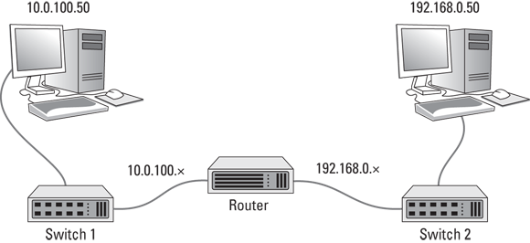
FIGURE 3-3: Two IP networks connected by a router.
Now suppose that the computer on the left side of the figure (10.0.100.50) needs to send a packet over to the computer on the right side of the figure (192.168.0.50). The sending computer forms the packet and sends it to Switch 1. Switch 1, in turn, sends the packet to the router. The router examines the destination IP address and determines that the destination computer is on the 192.168.0.50 network, so it forwards the packet over to Switch 2. Switch 2, in turn, forwards the packet to the destination computer.
Note that this exchange is actually considerably more complicated than the previous description lets on. For one thing, the switches — which don’t know about IP addresses — must determine the MAC addresses not only of the sending and receiving computers, but also of the router. And the router must also know the MAC addresses of the two switches. You’ll learn more about how this type of routing actually happens in Book 2, Chapter 4. But for now, I think you get the general idea.
The following sections describe a few of the other features commonly provided by routers.
Network address translation
When a router is used to connect a private network to the Internet, one of the router’s most important functions is routing traffic from all the computers on the private side of the router to the public side, which usually has just a single public IP address. To accomplish this magic, the router uses network address translation (NAT).
In short, when a computer on the private side of the network sends a packet through the router to the Internet, the router substitutes its own public IP address as the sender address, and keeps track of the fact that it sent a packet on behalf of a computer on the private side. When the recipient on the Internet receives the packet, it sees that the sender was the router. It then sends a response back to the router, which then substitutes the original sender’s private IP address for the destination address and forwards the packet to the correct computer on the private network.
For more information about NAT, see Book 2, Chapter 3.
Virtual private network
A virtual private network (VPN) is a secure connection between two private networks over a public network (in other words, over the Internet). All the data that flows over the VPN is encrypted, so anyone who steals packets from the VPN will find them unintelligible; only the parties on either end of the VPN are able to decrypt the packets.
VPN connections are often called tunnels, because they provide an isolated pathway from one point to another through the Internet. The only way to gain meaningful access to a VPN tunnel is at either end.
There are two common uses for VPNs:
- To provide remote workers with secure access to your company network: To do that, you set up a VPN on the router, and then provide your remote workers with the credentials necessary to access the VPN. The remote workers can run a software VPN client on their home computers or laptops to connect to your company network.
- To establish a tunnel directly between routers on two networks that are separated geographically: For example, suppose you have offices in Los Angeles and Las Vegas. You can use routers on both networks to establish a VPN tunnel between them. This effectively joins the networks together, so that devices on the Los Angeles network can freely exchange packets with devices on the Las Vegas network, and vice versa.
Figure 3-4 shows this arrangement. As you can see, the routers in both Los Angeles and Las Vegas are connected through the Internet via a VPN tunnel. This tunnel enables computers in Los Angeles and Las Vegas to communicate freely and securely with each other.
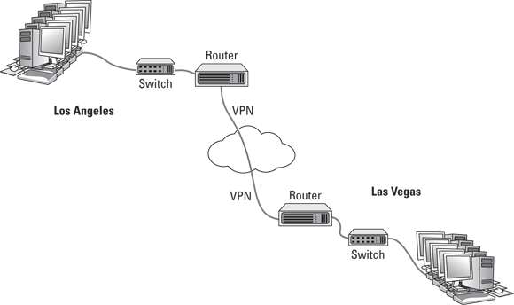
FIGURE 3-4: Connecting offices with a VPN tunnel.
For more information about working with VPN tunnels, refer to Book 4, Chapter 6.
Understanding VLANs
The final topic for this whirlwind introduction to switches and routers is the concept of VLANs. Most advanced switches allow you to create VLANs.
As its name suggests, a VLAN is a virtual network that runs on top of your actual physical network. VLANs work at layer 2 of the OSI model, which means that they’re related MAC addresses, not IP addresses. That said, there is usually a direct correlation between VLANs and IP subnets. If (or when) your network grows large enough that you want to set up two or more subnets to better manage it, you’ll probably also want to set up two or more VLANs, one for each of your subnets.
A VLAN can divide a single switch into two virtual switches that behave exactly as if they were separate switches. This means the following:
- If a port on one VLAN receives a packet intended for a destination on the same VLAN, the switch forwards the packet to the destination port, the same as if VLANs were not in use.
- When a port on one VLAN receives a packet intended for a destination on the same VLAN that the switch has not yet learned, the switch will flood only those ports that are on the destination VLAN — not all the ports on the switch. Thus, VLANs can reduce traffic caused by flooding.
- When a broadcast packet is received, the switch will forward the packet only to those ports that are on the same VLAN. In other words, VLANs can break up broadcast domains in the same way that a router can.
If a port on one VLAN receives a packet intended for a different VLAN, a router is required to link the networks. That’s because separate VLANs are, for all intents and purposes, separate networks.
That being said, most switches that support VLANs also support trunk ports, which can switch traffic between VLANs. A trunk port is a port that can handle traffic for two or more VLANs.
To use VLANs, you must manually configure each port of your switches to operate on the appropriate VLAN. By default, all switches regardless of manufacturer are configured out of the box so that all ports operate on a VLAN named VLAN1. To create a new VLAN, you simply create a name for the new VLAN, and then configure the ports that will talk on the new VLAN.
In VLAN terminology, a port that is configured to operate on a single VLAN is called an access port. Ports that are configured to work on more than one VLAN are called trunk ports. By default, all switch ports are configured as access ports on VLAN1.
Note that if you have more than one switch in your network, you can configure VLANs to work across the switches. For example, you can create a VLAN for your company’s accounting department — let’s call it VLAN-Acct. Then you can configure ports on any of your switches as access ports on VLAN-Acct. In this way, your entire accounting staff can operate on the accounting VLAN.