Dynamic virtual channel routers with congestion awareness†
Abstract
Buffer resources are key components of the on-chip router. In this chapter we propose two dynamic virtual channel (VC) structures. First, a dynamically allocated VC architecture with congestion awareness is introduced. All the buffers are shared among VCs, whose structure varies with the traffic condition. At a low rate, this structure extends the VC depth for continual transfers to reduce packet latencies. At a high rate, it dispenses many VCs and avoids congestion situations to improve the throughput. We modify the VC controller and VC allocation modules, and design simple congestion-avoidance logic. Second, we present a novel on-chip network router with a shared buffer based on a hierarchical bit-line buffer. The hierarchical bit-line buffer can be configured flexibly according to the traffic, and its inherent characteristic of low power consumption is also noticeable. A congestion-aware output port allocation scheme is used to assign higher priority to packets heading in lightly loaded directions. Also, an efficient run-time VC regulation scheme is proposed to configure the shared buffer so that VCs are allocated according to the loads of the network. Experimental results show that the proposed buffer structures are efficient for network-on-chip communication.
3.1 Introduction
In on-chip networks, communication resources such as buffers and links are finite and often shared by many packets in the time-division multiplexing [24] or spatial-division multiplexing [20, 36] way. Under heavy traffic conditions, multiple packets contend for the precious on-chip resources, leading to congestion situations. When congestion occurs, many packets will be blocked in the network and overall performance falls dramatically. Congestion management was proposed to prevent networks from becoming saturated and improve the throughput in the network-on-chip (NoC). Congestion can be avoided or relieved using various methods from the link layer to the application layer. At the link layer, high performance or flexible link techniques [17] are often employed to enhance packet-transferring capability. At the network layer, various techniques such as adaptive routing [11], wormhole flow control [10], and virtual channels (VCs) [26] can greatly reduce the congestion. At the application layer, congestion-aware task mapping [6] and scheduling [7] are often considered as effective approaches to avoid congestion.
According to the method of tackling congestion situations, the techniques mentioned above can be categorized into two groups. The first group, which comprises congestion-aware task mapping/scheduling and adaptive routing, first predicates the possible congestion, then adjusts the commutation path to avoid the upcoming congestion. Congestion-aware task mapping and scheduling is not the topic of this book, while adaptive routing, which targets an evenly distributed traffic load over the network, will be investigated in Part III. However, congestion cannot be avoided absolutely and often occurs in any NoC. In this situation, use of the other techniques belonging to the second group will make sense. With the help of wormhole flow control and VC techniques, buffer utilization achieves significant enhancement and congestion may be relieved. Almost all the on-chip networks have already employed these two techniques.
How to further enhance network performance and reduce congestion is a hot research domain, one important direction of which is the microarchitecture optimization, including designing few pipeline stages [18], efficient allocators [3, 25], high-speed links [32], and efficiently managed buffers [4]. From previous work [31], we know that the key inhibitor of performance in conventional VCs is the fixed structure, which results in serious network blocking or a large number of packet cross-transfers. This chapter exploits dynamic VC (DVC) buffer designs to avoid or relieve congestion. We first focus on DVC structures and analyze how to improve performance. Then, corresponding congestion awareness schemes for different DVC structures are investigated. Some specific packets will be picked and given higher priorities for moving to downstream nodes. As a result, precious buffer resources in the congested node will be released quickly, and the congestion situation may be avoided or quickly solved.
In on-chip routers, buffers are commonly implemented using either register-based FIFO buffers [28] or SRAM-based FIFO buffers [37]. Aiming at the two types of FIFO buffers, we propose two kinds of DVC structures with congestion awareness. The congestion awareness schemes dynamically allocate buffer resources to improve buffer utilization. The structures of two DVC buffers will be described in Sections 3.2 and 3.3, respectively. On the basis of the proposed DVC structures, two NoC router architectures are designed, and they will be described in Sections 3.4 and 3.5.
In this chapter we make the following main contributions:
• We propose two kinds of DVC structures.
• We propose corresponding congestion awareness schemes for DVC buffers to further optimize buffer allocation.
• We propose microarchitectures of two on-chip routers based on dynamic VC structures.
3.2 DVC with congestion awareness
3.2.1 DVC scheme
In an on-chip network, head-of-line (HoL) blocking and low link utilization are critical issues, especially for communication-intensive applications. Adaptive routing, wormhole flow control, and VC techniques can overcome these issues. Wormhole flow control and VC techniques are often adopted by the generic on-chip router, while simple deterministic routing algorithms such as source-based routing [5, 12] and dimensional order routing [9, 13] are employed instead of adaptive routing in order to reduce the complexity of on-chip routers. Deterministic algorithms do not avoid traffic congestion, and thus the network performance is degraded when the traffic pattern has localities.
Although the VC flow control scheme providing an alternative to reduce HoL blocking may improve link utilization, it brings with it lots of area and power overheads. For instance, the VC buffers will take up to nearly 50% of the area and will account for nearly 64% of leakage power in a router implemented under 70 nm CMOS technology [8]. There have been significant works on VC organizations to save buffers and exploit performance. Huang et al. [14] customized VCs and achieved 40% buffer savings without any performance degradation. However, they used a static approach which was based on a detailed analysis of application-specific traffic patterns. Tamir and Frazier [35] proposed a dynamically allocated multiqueue structure for communication on a multiprocessor. This architecture did not adapt to the NoC owing to the complex controller, the limited channel number, and the three-cycle delay for each flit arrival/departure. Nicopoulos et al. [28] introduced a DVC regulator which allocated a large number of VCs in high traffic conditions. It could not be scaled well to apply it to different traffic conditions, and dispensed many VCs with much complexity, whose overhead especially for the VC control table would increase nonlinearly. For instance, in the case of 16 buffers per port and a nine-flit packet size, the table size supporting 10 VCs will reach 220 bytes, nearly 21.5% of the total buffers.
Ideally, allocating more VCs implies better utilization on a given link, but it decreases the VC depth because of the fixed buffer size. Rezazad and Sarbaziazad [31] revealed that the optimal number of VCs depends on the traffic patterns when the buffer size is fixed. At low rates, increasing VC depths resulted in better performance. At high rates, the optimal structure depended on the distributing patterns. It was advisable to increase the VC count under a uniform pattern but extend the VC depth under matrix transpose or hotspot patterns. The statically allocated VC structure lacks flexibility in various traffic conditions and corresponds to low buffer utilization. Supposing routers are configured with few deep VCs, many blocking due to HoL blocking or lack of VCs at high rates will lead to low throughput. Inversely, if many shallow VCs are arranged, the packets are distributed over a large number of routers. At low rates, the continual packet transfers will be interrupted by many contentions, thus increasing the latency.
On the basis of the analysis above, we introduce a DVC scheme to overcome the limitations of static VCs. Figure 3.1 shows the DVC structure in detail. It includes v linked lists and a buffer track unit. The linked lists share all the buffers and each VC corresponds to a list for the single packet without any buffer reservation. When the flit is incoming, the appropriate list is selected according to the VC identifier. And then the arrival flit is stored in the tail buffer, which is dynamically allocated by the track unit. For the departure flit, the track unit is responsible for releasing the head buffer of the winning VC, which is arbitrated by the switch allocation (SA) unit.

In our structure, the VCs may be dynamically regulated according to the traffic conditions. At low rates, only a few channels are used. Each input port has enough buffers to be allocated for arrival flits. This structure ensures the continual transfer of packets without flow control, and is helpful to form a few deep channels. The packets distributing among few routers will reduce the average latency. At high rates, lots of VCs are allocated for the packet propagation. The increasing number of packets will result in many shallow channels, which improves throughput in two aspects. First, the scheme by which each packet uses a separate list avoids the HoL blocking, which is frequent in static VCs. Dispensing more VCs for the local packets will increase the channel multiplexing of physical links. Second, more VCs granted to upstream packets will decrease the blocking due to lack of VCs. In generic routers, many VCs may be occupied by the packets whose tail flits are blocked at upstream routers. At this moment, lots of buffers may be unused but the packets at neighboring routers are blocked owing to lack of VCs. More dispensed VCs here will accommodate many packets from the neighbors, improving throughput with a higher buffer utilization.
3.2.2 Congestion avoidance scheme
Although a DVC scheme brings throughput improvement for on-chip networks, a congestion awareness scheme will further improve the performance at high traffic rates. From the point of link utilization, three key factors restraining throughput in generic routers involve the blocking without a VC, the blocking due to flow control, and the crossbar contention, where two individual packets from different ports competing for the same physical link will make some other link idle. Dispensing lots of VCs may reduce the first type of blocking, and is helpful for reducing the crossbar contention by increasing the channel multiplexing. However, allocating more VCs makes no contribution to performance when congestion happens, where all buffers at the port are exhausted and the flow control is generated to prevent the upstream packets. Especially under a hotspot pattern, a great number of packets transferring toward routers with few buffers will result in frequent congestion situations. Once the packets have been blocked at local routers, the congestion will degrade seriously the link throughput.
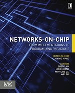
Figure 3.2a shows the effect of congestion. Packets p1 and p2 that transfer toward router C are blocked at router B owing to flow control or contention. A number of flits swarming into router B will lead to congestion at its west port. In the following, the upstream packets p3 and p4 will be blocked sequentially owing to flow control, incurring the idle state of links A→B, B→E, and B→D. If more buffers and VCs are allocated to packet p3 or packet p4 at router B, the link utilization may be increased linearly. But the buffers at the west port of router B have already been exhausted by packets p1 and p2 at this moment. Therefore, this scheme predicts the congestion of neighbors and inspects the traffic conditions around them. Once the local router senses a possible congestion in advance, it allocates buffers and grants high transmission priorities to packets traversing low traffic regions beyond the neighbor. Then, these packets will not be blocked by flow control at the neighboring router, and are good at avoiding the congestion by increasing channel multiplexing. As depicted in Figure 3.2b, supposing the west port of router B will not receive any flit in the next k cycles, the number of available buffers is aggregated k cycles ahead of time by predicting the minimum number of flits from the west port. If the aggregation value is no more than k, the continual transfer toward the west port of node B may cause possible congestion. In Figure 3.2b, the transfer request of packet p2 is cancelled and the transmission priority is granted to packet p3 or packet p4, which transfers toward the low-traffic routers beyond the neighbors. In the endthe congestion at the west port of node B is avoided and the throughputs of links A→BB→Eand B→D are improved.

3.3 Multiple-port shared buffer with congestion awareness
3.3.1 DVC scheme among multiple ports
The dynamically allocated VC scheme is an efficient way to improve the NoC performance, and we introduced a dynamically allocated VC structure in Section 3.2.1. In that structure, buffers in each channel are shared by different VCs. There is another type of dynamically allocated VC scheme, i.e., buffers are shared by all the channels. Several multiple-port shared buffer structures have been introduced [21, 22, 27]. These structures employ multiple-port register files to implement centralized memories, which may occupy much area and account for much power dissipation. Ramanujam et al. [30] proposed a shared-buffer router architecture to emulate an output-buffered router, which results in a high throughout. In their design, several normal buffers are sandwiched in two crossbar stages. The buffer structures are simplified, but this may also bring some problems. A flit is usually stored in the input channel buffers and then moved to the middle memory, which may lead to extra flit traversals. Flits in the buffer were time-stamped in first come, first served order, and flits of the same packet cannot be transferred continuously, which may cause higher average packet latencies.
In this section, we propose a novel DVC structure based on a hierarchical bit-line buffer (HiBB) aiming at low cost and high performance. The VC buffers can be shared by several input channels according to the traffic status, and the input channel with heavier loads can win more VCs than the others. Furthermore, the proposed buffer structure brings potential advantages in power consumption and link utilization. When a VC is in the idle state, it can be power gated easily for the characteristic of the HiBB, which results in great power savings. In the generic router, multiple packets in input channels are arbitrated, and winning packets traverse the crossbar. The link utilization may be affected by the inefficient arbitration. In the HiBB, packets aiming at the same direction are switched to the corresponding output port inside the buffer, and a scheme named the output-port allocation is proposed to directly select a packet to serve. This scheme improves the link utilization, and it also reduces the router complexity.
In the HiBB structure, cells of each VC are connected to a sub bit-line, and the sub bit-line is connected to several bit-lines corresponding to input or output channels of the router via pass transistors. In order to reduce the area overhead due to the increased number of bit-lines, we further employ three schemes to optimize the HiBB structure: (1) single-ended 6T SRAM cells [34] are adopted to reduce area overheads and power consumption; (2) the higher metal layers are used for routing increased numbers of bit-lines to reduce the area; (3) each shared VC is shared by only a few input channels instead of all the input channels.
Figure 3.3a shows an example of the third scheme described above. There are five private VCs and eight shared VCs in the HiBB router. Each private VC is allocated to one input channel exclusively, and each shared VC can be shared between two neighboring input channels. For instance, the VC identified by “1” is shared between the west and north channels, while the VC identified by “3” is shared between the west and south channels. Figure 3.3b shows how buffers are customized under a specific traffic load. The west channel is allocated four shared VCs, and the south channel has two shared VCs. Two shared VCs are left unallocated, and they can be switched to be in a sleep state to achieve power reduction [1]. We use a set of registers to control the global word-lines to regulate VCs, and the process of buffer customization is accomplished by writing configuration information into the configuration registers.

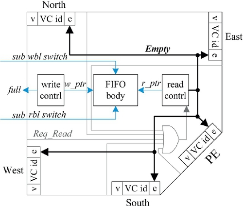
The detailed structure of the proposed unified buffer is shown in Figure 3.4. For briefness, just one column of a VC is displayed in the figure. Each memory cell has only one write port and one read port, which connect to a sub write bit-line (sub wbl) and a sub read bit-line (sub rbl) respectively. Each input channel is connected to a write bit-line (wbl) and each output channel is connected to a read bit-line (rbl). Sub bit-lines and bit-lines are linked via pass transistors, and the global word-lines are responsible for turning on and off pass transistors. When memory cells are assigned to an input channel, the sub wbl is switched to a wbl. When a packet enters the VC, the routing computation (RC) results are used to switch the sub rbl to a specific rbl. The structure of the VC remains unchanged during the process, so the flits of a packet traverse from the input channel to an output channel, which results in power optimization owing to reduced switch activities.

3.3.2 Congestion avoidance scheme
For the DVC structure, buffers are dispensed or adjusted under two conditions. First, when one input channel is congested, more VCs will be established to avoid HoL blocking. Second, the buffer is dispensed with higher priorities for those packets aiming at lowly loaded directions in order to avoid exhausting precious buffer resources. Similarly to the DVC scheme, a congestion awareness scheme was also proposed for the HiBB to further optimize the performance. The packets heading to an output channel are first transferred to a neighboring input channel of the next hop, and are then transferred in one direction according to the RC information. As shown in Figure 3.5, if packet p2 heading in a congested direction is selected and served, it may be blocked in the next hop, B. As a result, the limited buffer resources are exhausted and packets (p1 and p3) heading in lightly loaded directions may also be blocked for the lack of buffers. If packet p1 or packet p3 is served, the congestion of the total network will be greatly relieved.
For the HiBB, the VC is shared by several input channels, and VCs can be dispensed to those inputs with heavier traffic loads. This feature is similar to that of the DVC buffer. The DVC router dispenses buffers in an individual channel with flit granularity, while the HiBB router dispenses buffers among multiple channels with VC granularity. The main goal of the congestion avoidance scheme for the DVC buffer is to avoid exhausting the buffer rapidly, and the goal of the congestion avoidance scheme for the HiBB is to release the VC as soon as possible. The essence of the two congestion avoidance schemes is to improve buffer utilization. As a result, more buffer resources are dispensed to improve packet transmission.
3.4 DVC router microarchitecture
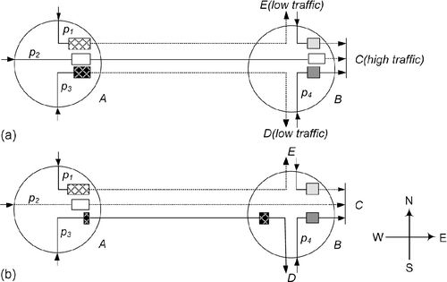
The generic VC router was presented by Peh and Dally [29]. It was an input-queued router with four direction ports and a local port. The key components included the buffer storages, VC controller, routing module, VC allocation module, SA module, and switch component. The routers used VCs to avoid deadlock and improve throughput. On the basis of the generic router and DVC buffers, we design a DVC router whose architecture is shown in Figure 3.6. The main difference between the DVC router and the generic router is the VC organization. When a flit arrives at an input channel of the DVC router, it can be written into any slot of the buffer according to the command of the VC controller. When a flit in the buffer wants to transfer to the next hop, the congestion-aware flow control module will pick the packet aiming at directions with low loads. In this section, we describe the microarchitecture of the VC controller and VC allocation modules, as well as the design of the simple congestion avoidance logic.
3.4.1 VC control module
The generic routers are deployed with several fixed VCs to share physical links. Each arrival/departure flit selects its individual FIFO controller unit according to the VC identifier. Instead, each input port in our modified routers adopts the uniform VC control logic, which generates the buffer indexes by VC identifiers in one-cycle delay. The port includes v linked lists, and the relative information about each VC involves the valid tag, the link head pointer (HP), the tail pointer (TP), the requested channel identifier, and the transfer directions at the local hop (DIR) as well as the transfer directions at the next hop (NDIR). The main information about each list item includes the buffer storage and next flit pointer (NP) to the following flit.
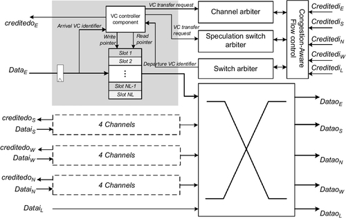
Figure 3.7 shows the VC control logic for flit arrival/departure in detail. The key elements include the HP register file, the TP register file, the next slot pointer register file, and a free buffer track unit. For each arrival flit, the write index is generated when three operations have been completed as shown in Equations (3.1)–(3.3):
At the beginning of each cycle, the track unit returns an available buffer index to accommodate the arrival flit. Also, with use of the VC identifier, the TP information of the right link and the NP information of the right tail are updated by the available buffer index at the next clock rising edge.
On the other hand, each departure flit corresponds to another three operations as shown in Equations (3.4)–(3.6):
As depicted in Figure 3.7, the compare unit first judges the continual transfer of a certain packet by comparing VC identifiers of successive requestors. If the latter flit follows the former one within the same channel, the compare unit generates the true result and the NP content selected by the last read index will be the current read index. Otherwise, the departure VC identifier is used to select the right HP content to be the read index as shown in Equation (3.4). Each departure flit also needs to update the HP register file. As shown in Equation (3.5), if the input port wins the second SA phase, the right HP will be updated by NP information of the last departure flit. Finally, for each departure flit, the track unit clears the corresponding bit to release the occupied buffer as shown in Equation (3.6). In this structure, all the operations work in parallel with the SA process within one-cycle delay, and there is negligible impact on the critical path. The extra hardware cost is also limited owing to there being few register files. Supposing the flit width bits, VC number, buffer number, and maximum VC depth are 128, 10, 16, and 9 respectively, the storage overhead is nearly 7.0%.
3.4.2 Metric aggregation and congestion avoidance
As discussed in Section 3.2.2, we predict the congestion situation at immediate neighbors. Figure 3.8 shows the congestion metric aggregation module. Supposing the current time stamp is t, then ncd(t,k) (d = E, …, N) predicts how many flits will leave from the immediate neighbor in direction d over the next k cycles. Further, bd(t,k) predicts the availability of its input buffers in k cycles ahead of time. The right box in Figure 3.8 shows the input port of the neighbor. Its key components include the first SA unit and a prediction unit. The SA unit arbitrates among all the requests from the same port and grants transfer priority to the winner. The prediction unit calculates the number of departure flits from its input port over the next k cycles. The neighbor has already aggregated the availability information bq(t,k) in the winner's output direction. In the wormhole switching scheme, the winning packets are served continuously until the tail flit. When any condition happens, the first allocation phase grants the transfer priority in a round-robin order to other packets. Thus, the prediction unit of the neighbor calculates the number of departure flits as shown in Equation (3.7):
where k denotes the stride and lw denotes the list length of the winner. The left box in Figure 3.8 represents the local router. The canonical router records the available buffers of its immediate neighbors for flow control, and we name them as xd(t). The modified module aggregates the available buffers at its neighbor input port k cycles ahead of time by the sum of xd(t) and ncd(t,k), as depicted in Figure 3.8. If the prediction value is no more than k, the congestion metric congd will be true. This means that the packet transfers to direction d may cause congestion.

Then, the transmission priority is granted to packets which transfer toward low-traffic regions beyond neighbor routers to avoid congestion. As shown in Figure 3.8, each router collects the available buffers at neighbor inputsand aggregates the traffic metricsΔ where E, S, W, and N denote metrics in different directions. We performed a detailed empirical evaluation to determine the threshold for metric, and found that a value which was a little more than stride k was reasonable for packet bypass. Since the routers can sense the possible congestion situations at neighbors, they may use traffic metrics to advance the packets which transfer toward low-traffic regions beyond neighbors.
As shown in Figure 3.9, the modified flow control module consists of two parts. First, similarly to the generic router, each channel compares its remote VC length with the FIFO depth to determine the flow control. Our modified module adopts the FIFO depth, which varies with the number of VCs. At a high rate, the VC depth at the neighbor is reduced reasonably for more packet propagations due to many VCs. Second, the transfer requests toward high-traffic regions beyond neighbors are masked when predicting congestion. Each input port is deployed with several avoidance units which correspond to other output directions. Utilizing DIR information, each channel exports its NDIR information to the right avoidance unit by the demultiplexer unit. The avoidance unit collects all NDIR information within the same port and specifies the mask bit of each VC. It uses multiplexers to select the traffic metric of the next output direction. The relative mask bit will be set to be true when the packet transfers toward the high-traffic region beyond the neighbor. However, if all the packets are transferring toward high-traffic regions beyond the same neighbor, the avoidance unit will not mask any request and will set all bits to be false.

In the modified module, each list uses its DIR information to select the congestion metric and the mask bit. When both conditions are true, the transfer valid signal will be canceled. With use of this approach, the packets heading toward low-traffic regions beyond neighbors are transferred in advance when predicting congestions. Note that for the packets from different input ports, the transfer priority is decided by the second SA phase according to the traffic metrics. If the prediction metric ncd(t,k) is summarized into 3 bits, plus 3 bits for the traffic metrics, this scheme requires an extra 6 bits per link, and the wire overhead is just 4.1%. This scheme has no influence on the critical path, and the area overhead from the prediction and avoidance units is confirmed to be low in the following synthesis.
3.4.3 VC allocation module
The VC allocation in the generic router was performed in two stages, which arranged v:1 and 5v:1 arbiters respectively. With increasing number of VCs, the VC allocation module, which relies on the critical path, will influence the performance. The modified VC allocation module adopts another two-phase arbitration. The first phase arranges five v:1 arbiters at each input port and every arbiter gains a winner request in the corresponding direction. The second-phase logic distributes at each output port, which arranges a 5:1 arbiter to generate the final winner to occupy dispensed VCs. Although the proposed module allocates a single VC in each direction, it has negligible impact on the performance. Even if more VCs are dispensed, the flits still transfer toward the output port one by one. The main advantage of the modified structure is that the area overhead and critical path length are reduced owing to there being few 5:1 arbiters instead of many 5v:1 ones. In addition, each output port arranges a VC manage unit for VC dispensation. It dispenses lots of VCs for request packets until the VCs are exhausted, and releases VCs according to the credits from neighbors. For the allocation scheme, the second phase arbitrates for the winners according to the traffic metrics from neighbors, granting the VC allocation priority to the packets which transfer toward the low-traffic regions beyond neighbors.
3.5 HiBB router microarchitecture
On the basis of the analysis presented in Section 3.3, we introduce a new shared-buffer router which employs an HiBB to overcome the limitations of existing buffer structures. Figure 3.10 shows the proposed HiBB router architecture. In the new router, VCs are shared among different input channels. These VCs will be allocated to each channel dynamically according to the traffic situation of the channel, i.e., heavily loaded channels will get more VCs, and lightly loaded channels will get fewer. Note also that the VC allocation (VA) module, the SA module, and the crossbar switch in our HiBB router are highly simplified compared with those in the generic router.

When a flit arrives at an input channel of the HiBB router, it is written into a specific VC. If the flit is a header flit, the output port direction is computed by the RC module. At the same time, the read port of the VC switches to an output channel according to the result of the RC. As a result, all the VCs containing packets with the same direction are connected to a single output channel. After the header flit enters a VC, it requests a VC in the next hop and the VA module is responsible for the VC allocation. Then, the packet which is assigned to a VC can transfer to the output channel. As there may be several packets applying for traversal, instead of using the traditional switch allocator, we use an output port allocator (OA) module to select a packet for traversal. The structure and principle of the OA will be explained in detail in Section 3.5.2.
If the buffers are implemented using register-based FIFO buffers, there will be many multiplexer gates to select registers for specific input or output channels. If the buffers are implemented using SRAM-based FIFO buffers, each cell will have many read ports and write ports. Both of these implementations increase the design complexity, leading to more area and power overhead. The HiBB has an inherent characteristic of low power [15], and it avoids the problem suffered by multiple-port buffers.
3.5.1 VC control module
To reduce the hardware overhead of the VC control logic, we introduce virtual controllers to control VCs. For each FIFO body, there is a write controller, a read controller, and several virtual write/read controllers. Figure 3.11 shows the structure of the VC control module in our router. Suppose that the FIFO body is allocated to the west port, and the virtual write controller is omitted. Because packets from the west channel may head for the other four directions, four virtual read controllers are used here. Each virtual controller contains several items: a valid tag (v), a VC identifier, and an empty tag (e). When a packet in the FIFO body flows to a certain output channel, the tag v in the virtual read controller of this direction is set to be valid. The FIFO body is managed according to the information in the virtual controller. If a channel needs to read a FIFO buffer, the virtual controller will send a read request to the read controller of the FIFO buffers. After receiving a read request, the read controller reads a flit and sends it directly to the requesting channel. At the same time, the tag e in the virtual read controller is updated.
3.5.2 VC allocation and output port allocation
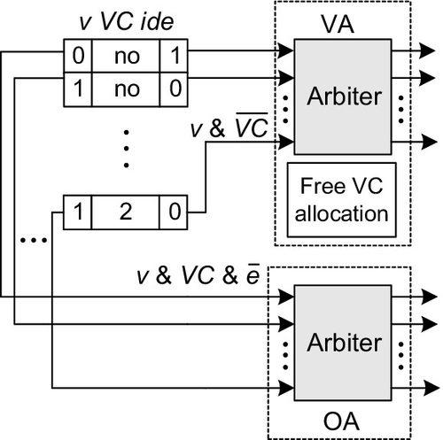
Before the packet in the present hop flows downstream, the VA module is usually employed to allocate a VC in the next hop to it. In the generic router, packets in different input channels may request the same VC, and two allocation stages are often used [29]. In our router, the VA module is much simpler than the corresponding module in the generic router. Specifically, an allocation module similar to the technique used in Ref. [28] is presented, as shown in Figure 3.12. All the VCs requesting the same output channel have a valid tag (v = 1) in the virtual FIFO controllers. This information can be used in the process of VA. All the virtual controllers in an output channel send requests to an arbiter to determine which one will gain a VC, and then the free VC allocation module allocates an available VC recorded in the free VC table to the winner.
In the generic router, the crossbar switch transfers packets or flits from input channels to output channels. The SA unit arbitrates among all VCs requesting access to the crossbar and grants permissions to the winners. Then, the winning flits are able to traverse the crossbar. In order to fully utilize the link bandwidth, highly efficient scheduling algorithms have been exploited [2]. However, it is very difficult to achieve a maximum size matching between input channels and output channels with high-performance implementation because of their complexity [23].
On the basis of the proposed HiBB, the SA and crossbar can be simplified. When a new packet enters a VC, the sub bit-line of the VC is switched to the bit-line of the corresponding output channel. As a result, all the VCs containing packets heading in the same direction are connected to a single output channel. In each clock cycle, the output channel reads a flit out of the VCs connected to it directly and then sends it to the output link. The OA module, which is also shown in Figure 3.12, can fulfill the requirements of the packet traversal in the HiBB router. Owing to the simplified structure, several other benefits are obtained:
(1) a maximum size matching can be achieved with simple hardware overhead;
(2) a VC maintains its read port connection until the tail flit leaves the VC, which may result in lower power consumption compared with the more frequent switching in the crossbar in a generic router.
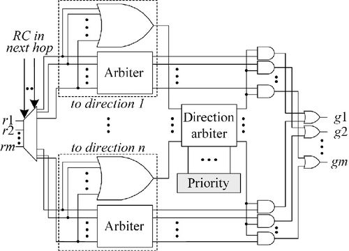
The packets heading to an output channel are firstly transferred to a neighboring input channel of the next hop, and are then transferred in one direction according to the RC information. If the packet heading in a congested direction is selected and served, it may be blocked in the next hop. As a result, the limited buffer resources are exhausted and packets heading in lightly loaded directions may also be blocked because of the lack of buffers. To further improve the performance of the total network, we introduce a more efficient arbiter structure with congestion awareness, as shown in Figure 3.13. In the new arbiter structure, we classify the requests into n types according to the possible packet directions in the next hop and arbitrate them separately. At the same time, the possible directions of the next hop are also arbitrated using a dynamic priority arbiter [16]. As a result, the packet heading in the direction with the highest priority is selected to serve. The priorities of the dynamic priority arbiter are determined by the congestion situation of each direction in the next hop, i.e., the congested directions will be assigned with lower priorities while others will be assigned with higher priorities.
3.5.3 VC regulation
Since each VC may be used by several input channels, configuration information is needed for the VC regulation. We use a set of configuration registers to store the configuration information. To utilize the flexibility of the HiBB further, we introduce a run-time configuration scheme. During the process of communications in an NoC, we predicate the importance of a VC to each input channel. If an input channel needs a new VC aggressively, the idle VC will be assigned to this channel with higher priority. Otherwise, an idle VC may be reassigned to other channels or set to be in a sleep state.
Figure 3.14 shows the run-time regulation scheme of the HiBB router. Each output channel predicts the possibility of a new VC request in the next k cycles and sends it to the neighboring input channel. The precondition of requesting a new VC is that the following three conditions must be satisfied. The first condition is that the remaining length of the packet being served is less than k. In the wormhole switching scheme, the winning packets are served continuously until the tail flit, flow control, or empty channel. If this condition is satisfied, the packet may not be served continuously and a new VC may be needed. The second condition is that the result of the direction arbiter in the OA and the direction of the winning packet in VA are not equal. If the two values are equal, there is already a packet heading in the same direction as the winner of VA which can be served in the following cycles. The third condition is that the output of the VC arbiter is not equal to zero. If the output of the VC arbiter is equal to zero, this means that there is no packet in the output channel requesting a new VC. After the output channel has predicted a possible VC request, the predicted information will be used by its neighboring input channel to calculate whether a new VC should be assigned. Besides, the existing available idle VC number (Nidle) and potential idle VC number (Npotential) are also used. Npotential indicates how many VCs containing packets will be released in the next k cycles. The information on existing VCs and the VCs being served from local output channels is taken to estimate whether the tail of the packet will leave the current VC. If the sum of Nidle and Npotential is smaller than the predicted VC request number, the corresponding input channel requires a new VC allocation imminently. If the sum is much bigger than the predicted VC request number, the idle VCs in the input channel are redundant and they can be reclaimed for power reduction. The regulation module collects the information described above to do the VC switching. In this book, we set k as the number of cycles for a VC allocation.

3.6 Evaluation
3.6.1 DVC router evaluation
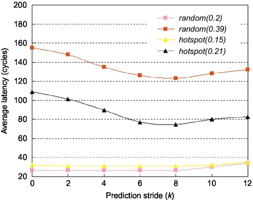
We use a cycle-accurate simulator to evaluate the performance. The generic router employs a simple dimensional order routing algorithm and adopts a lookahead scheme which corresponds to a three-stage pipeline scheme. In the experiment, each input of the routers is deployed with 32 buffers. There are two kinds of generic routers, denoted as T-2 and T-4 respectively, according to the VC number, in contrast with 10 VCs at most in our DVC routers. We arrange different 8 × 8 mesh networks using three routers and perform simulations under uniform and hotspot patterns with a packet size of nine flits (one flit for the head plus eights flits for the body, 16 bytes per flit). The results were obtained by simulating 1 × 10⁶ cycles for different rates or patterns after a warm-up phase of 2 × 10⁵ cycles. First, the effect of prediction stride k on average latency is investigated. The latency is shown as a function of stride k for different traffic rates in Figure 3.15. When k increases from 0 to 8, the latencies remain steady at a low rate but decrease rapidly at a high rate. A stride value of 0 means that the congestion awareness scheme is not adopted. In this case, many allocated VCs may reduce the blocking caused by lack of VCs, but are of no use for the flow control, which will leave many links idle. With the increase of k, the congestion situations will be gradually reduced to improve link utilization. However, when stride k increases from 8 to 16, the average latency begins to increase. If a greater value is used for k, it may always predict congestion situations which will interrupt the continual packet transfers. Thus, we set k to be 8 with a buffer size of 32 to gain better performance.
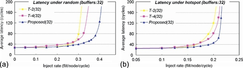
In the following, the performances of DVC and generic routers are evaluated. Figure 3.16a illustrates the results obtained under a random pattern. At a low rate, T-2 and DVC routers may provide deep channels, which correspond to low latency. But with an increase of the rate, the performance of the T-2 router tends to be saturated rapidly. The T-4 router uses more VCs to improve the throughput, but its performance is still limited by serious HoL blocking or blocking caused by lack of VCs. Here, we observe the advantages of the DVC router in detail. It avoids HoL blockings and dispenses many VCs at a high rate. Also, it avoids the congestions to improve throughput. As a result, the saturated throughput of the DVC router outperforms the T-2 and T-4 routers by nearly 33.9% and 22.1% respectively. Figure 3.16b illustrates the results obtained under a hotspot pattern. At a low rate, the DVC router also has low latency owing to deep channels. With increase of the rate, a few routers become the high-traffic nodes and the others are still in the low-traffic state. DVC routers allocate VCs according to local conditions. At low-traffic nodes, they extend the VC depth to decrease average latency. Around the hotspot, they dispense many VCs to increase channel multiplexing. In particular, it grants transfer priority to packets heading toward low-traffic regions, and then many packets heading toward low-traffic destinations will not be blocked around the hotspot node. In Figure 3.16b we select typical injection rates from 0.10 flits per cycle to saturated points, and the average latency drops by nearly 30.2% and 25.2% respectively.
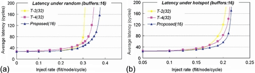
In the generic routers, the buffer utilization is low owing to the limited number of VCs. We also evaluate the performance of the DVC router when the buffer size is reduced to 16. Using the same quantified method, we set stride k to be 4 for better performance in all cases. Figure 3.17 shows the average latency as a function of the injection rate. Under a random pattern, the saturated rates of the three routers are about 0.38, 0.34, and 0.31 flits per cycle respectively. Compared with the T-2 router, the average latency of the DVC router is decreased by 16.5% when we select 0.1,0.2, 0.275, and 0.3 flits per cycle as typical rates. With rates of 0.1,0.2,0.3, and 0.325 flits per cycle, the latency of the DVC router outperforms the T-4 router by about 21.6%. Then, the saturated rates are measured to be 0.20, 0.21, and 0.22 flits per cycle under the hotspot pattern, and the DVC router achieves reductions in latency of 20.3% and 17.6% respectively, compared with the other two routers. On average, compared with the T-4 router, which is superior to the T-2 router, the DVC router provides an 8.3% increase in throughput and a 19.6% decrease in latency.
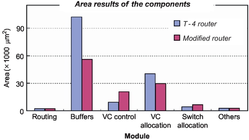
Finally, we complete the RTL-level description of the DVC router using 16 buffers and 10 VCs. The VLSI design results for the 90 nm process show that the router can operate at 600 MHz. The area information of each module is illustrated in Figure 3.18. The main area overhead comes from the VC control module owing to it accessing index generation and congestion avoidance logic. But halving the number of buffers and a simplified VC allocation module result in greater area reduction, and the total area saving is nearly 27.4%. Using PrimePower, we also estimated the power consumption of the routers, excluding the wire power consumption. The power consumption of the DVC router decreases by 28.6% compared with that of the T-4 router.
3.6.2 HiBB router evaluation
In this section, we implement the HiBB under 90 nm CMOS technology. The memory array of the HiBB is implemented by full custom design flow and its control logic is implemented by standard cell-based design flow. Figure 3.19 shows the area and power comparison results for the HiBB and the generic buffer with different VC numbers. The generic buffer consists of four independent small buffer structures, and each small buffer structure contains several VCs of 128-bit width and eight-flit depth. In the HiBB, equivalent VCs constitute a unified buffer. From Figure 3.19a, we can conclude that the area of the HiBB is a little bigger than that of the corresponding generic buffer under the same capacity. However, the area does not increase much owing to the use of virtual VC controllers and the three schemes proposed in Section 3.3.1. The increased area of the HiBB is mainly because of the introduction of pass transistors connecting two levels of bit-lines and the sleep transistors.

The powers needed to access the traditional buffer and the HiBB are compared for a frequency of 500 MHz. The power result shown in Figure 3.19b is just the power consumed by the activity of one port. The total power is related to the read-write number, so it may increase linearly when there are several ports working simultaneously. It is obvious that the HiBB is much more power efficient than the generic buffer under the same capacity. The hierarchical bit-line reduces the load capacitance of the bit-line, which may be the reason for the power reduction.
For 90 nm technology, the proposed HiBB router can operate at 500 MHz. The area overheads of the generic router and the HiBB router are shown in Figure 3.20. Each input channel of the generic router has four VCs, while the HiBB router has a unified buffer with the same number of VCs. It can be calculated that the HiBB router incurs a little more area overhead for the buffers and VC control logic. The area of the OA is greatly raised owing to the use of the improved arbiter with the congestion awareness scheme. The complexity of VA is greatly reduced, leading to an area reduction of about 29.5 × 103 μm2. In addition, the crossbar switch is eliminated in the HiBB router, and plenty of silicon area is saved. As a result, the HiBB router can achieve a 6.9% total area saving compared with the generic router. Besides, if the new arbiter with the congestion awareness scheme is not adopted in the HiBB router, the area of the simple OA logic is just 2.1 × 103 μm2, and the HiBB router can achieve an area saving of about 22.1%.

To evaluate the performance of the proposed HiBB router architecture, we built two 8 × 8 mesh cycle-accurate NoC simulators using XY deterministic routing. The first simulator employs the generic router, while the second one adopts the HiBB router. During simulation, we assume the nodes inject packets at regular intervals. In each input channel of the generic router there can be one, two, and four VCs respectively. The unified buffer in the HiBB router can be configured with 4, 8, and 16 VCs. To evaluate the power consumption of the HiBB router, two 8 × 8 mesh NoC gate-level implementations are also completed. Then, different traffic patterns are inputted into the gate-level netlist of the NoC to obtain value change dump (VCD) files. Finally, simulated gate-level power consumptions are collected using PrimePower.
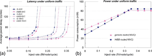
The performance and the power consumption of the HiBB router are first evaluated under uniform traffic patterns. As illustrated in Figure 3.21a, the performance of the HiBB network is a little better than that of the generic network. Because the traffic is uniform, each input channel of the HiBB router is configured with the same VCs. The performance improvement is due to the OA scheme. In each cycle, one output port selects a requesting packet connected to it and the conflicts between multiple output ports are eliminated. As a result, the link efficiencies are enhanced. The power consumptions of the generic and HiBB routers are shown in Figure 3.21b. Under light traffic, the power consumption of the HiBB router is lower than that of the generic one. This is because some idle VCs in the HiBB router can be set to the sleep state to save power under light traffic. When the whole network is idle, the HiBB router can achieve power savings of about 30%. However, the HiBB router consumes a little more power than the generic router under heavy traffic. The reason is that all the VCs in the HiBB are utilized and little power is saved. At the same time, more flits are transferred owing to the performance improvement of the HiBB router, causing a power consumption increase. The power consumption of the HiBB router may be up to 3.7% higher than that of the generic router.
Then, we configure the generic router with four uniformly allocated VCs across all links and configure the HiBB router with an HiBB employing the same VCs. Three nonuniform traffic patterns are chosen, which are hotspot, matrix transpose, and random. In the random traffic pattern, we ensure that just several nodes are communicating with each other and the others are idle. Each traffic pattern can employ different traffic loads. For instance, the hotspot patterns with a light load and a heavy load are labeled as hotspot-L and hotspot-H respectively in Figure 3.22. The performance and power consumption for the six traffic patterns are shown in Figure 3.22.

For hotspot and transpose patterns, the average packet delay of the generic router increases rapidly as the traffic load becomes heavy, while the average delay of the HiBB router increases less sharply. For random traffic, the average packet delay of the two networks is much smaller than the delay under the hotspot and transpose patterns. This is because just several neighboring routers are picked for communication, and the communication links are often short.
Under light loads, the average power consumption of the HiBB router is lower than that of the generic router as there are abundant VCs in the sleep state. As the traffic load increases, the power consumption of the HiBB router becomes 5.7% and 4.6% higher than that of the generic router for the hotspot and transpose patterns respectively. The power saving from the HiBB is surpassed by the power consumption increase from additional transferred flits. However, the power consumption of the HiBB router is still less than that of the generic router under random traffic. In random traffic, there are a lot of idle routers and the idle VCs can be set to the sleep state, resulting in great power savings. When the traffic load becomes heavy for just several links, the average power consumption of the HiBB router, which is about 75% of that of the generic router, remains almost the same.
3.7 Chapter Summary
In on-chip networks, many packets contend for finite communication resources. The VC organization structure has a great effect on network throughput. In this chapter we proposed two DVC structures, and also corresponding congestion awareness schemes to enhance further the resource utilization. In the first type of DVC, buffers in each channel are shared by different VCs. For low-rate traffic, it extends deep VCs to reduce packet latency, while it increases the VC number and avoids congestion situations to improve throughput under high-rate traffic. In the second type of DVC, buffers can be shared by several input channels according to the traffic information, and the input channel with the heaviest load can win more available VCs than the input channels. We proposed a shared buffer based on an HiBB to implement the second type of DVC. Finally, two DVC routers were designed and evaluated.