
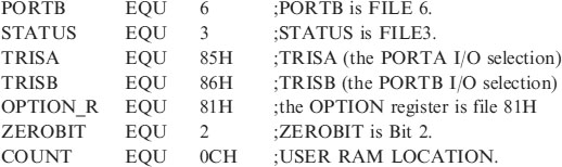
5
Using inputs
A control program usually requires more than turning outputs on and off. They switch on and off because an event has happened. This event is then connected to the input of the microcontroller to ‘tell’ it what to do next. The input could de derived from a switch or it could come from a sensor measuring temperature, light levels, soil moisture, air quality, fluid pressure, engine speed etc.
Analogue inputs are dealt with later, in this chapter we will concern ourselves with digital on/off inputs.
New instructions used in this chapter:
As an example let us design a circuit so that switch, SW1 will turn an LED on and off.
The circuit diagram is shown in Figure 5.1.
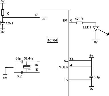
Figure 5.1 Circuit diagram of the microcontroller switch
This circuit is using the 16F84 microcontroller with a 32kHz crystal.
It can of course also be performed with any of the microcontrollers discussed previously. Including the 16F818 using its internal oscillator, in which case the crystal and 2 × 68pF capacitors are not required.
The program to control the hardware would use the following steps:
In the circuit diagram SW1 is connected to A0 and LED1 to B0.
When the switch is closed A0 goes low or clear. So we wait until A0 is clear. The code for this is:
| BEGIN | BTFSC | PORTA, 0 (test bit 0 in file PORTA skip if clear) |
| GOTO | BEGIN | |
| BSF | PORTB, 0 |
• The command BTFSC is Bit Test in File Skip if Clear, and the instruction BTFSC PORTA,0 means Test the Bit in the File PORTA, i.e. Bit0, Skip the next instruction if Clear. If A0 is Clear Skip the next instruction (GOTO BEGIN) if it isn't Clear then do not Skip and GOTO BEGIN to check the switch again.
The program will check the switch thousands maybe millions of times a second, depending on your clock.
• When the switch is pressed the program moves on and executes the instruction BSF PORTB,0 to turn on the LED.
We then wait for the switch to open.
When the switch is open A0 goes Hi or Set, we then wait until A0 is Set i.e.
| SWOFF | BTFSS | PORTA, 0 |
| GOTO | SWOFF | |
| BCF | PORTB, 0 | |
| GOTO | BEGIN |
• The command BTFSS is Bit Test in File Skip if Set, and the instruction BTFSS PORTA,0 means Test the Bit in the File PORTA, i.e. Bit0, Skip the next instruction if Set. If A0 is Set Skip the next instruction (GOTO SWOFF) if it isn't Set then do not Skip and GOTO SWOFF to check the switch again.
• When the switch is set the program moves on and executes the instruction BCF PORTB,0 to switch off the LED.
The program is now added to the header. (NB. Use the TAB to make your listing easy to read.) It is then saved as SWITCH.ASM.
;*********************************************************
;Program starts now.
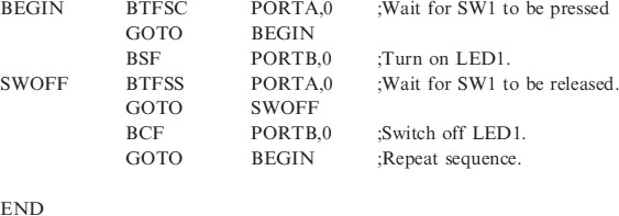
Switch flowchart
It will be obvious from the program listing of the solution to the switch problem that listings are difficult to follow. A picture is worth a thousand words has never been more apt than it is with a program listing. The picture of the program is shown below in the flowchart for the solution to our initial switch problem, Figure 5.2. Before a programming listing is attempted it is very worthwhile drawing a flowchart to depict the program steps. Diamonds are used to show a decision (i.e. a branch) and rectangles are used to show a command. Each shape may take several lines of program to implement. But the idea of the flowchart should be evident. Note that the flowchart describes the problem – you can draw it without any knowledge of the instruction set.
Figure 5.2 Flowchart for the switch
Program development
From our basic switch circuit an obvious addition would be to include a delay so that the LED would go off automatically after a set time.
Suppose we wish to switch the light on for 5 seconds, using A0 as the switch input. Figure 5.3 shows this Delay Flowchart.
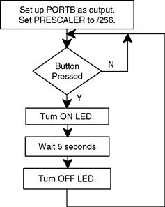
Figure 5.3 Delay flowchart
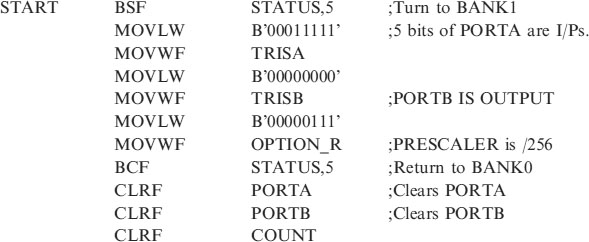
The complete listing for this program for the 16F84 is shown below. I have shown the complete code including the header because I have added a 5 second delay in the subroutine section.
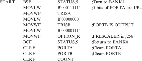
;EQUATES SECTION
![]()
;**********************************************************
| LIST | P = 16F84 | ;We are using the 16F84. |
| ORG | 0 | ;0 is the start address. |
| GOTO | START | ;goto start! |
;**********************************************************
;Configuration Bits
| __CONFIG H’3FF0’ | ;selects LP oscillator, WDT off, PUT on, |
| ;Code Protection disabled. |
;*****************************************************
;SUBROUTINE SECTION.
;5 second delay.
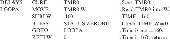
;**********************************************************
;CONFIGURATION SECTION.
;*********************************************************
How does it work?
• We check to see if the switch has been pressed (clear). If not GOTO ON and check again. If it has skip that line and Turn on the LED on B0.The code is:
• Wait 5 seconds. The 5 second delay has been included for you in the subroutine section. Code:
| CALL | DELAY5 |
| BCF | PORTB, 0 | ;Turn off LED. |
| GOTO | ON |
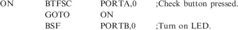
| Problem 1: |
The flowchart for the solution to problem1 is shown in Figure 5.4
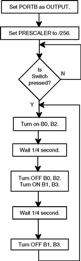
Figure 5.4 Flowchart for problem
Program solution to problem1 for the 16F84
;PROBLEM1.ASM
;EQUATES SECTION
;*********************************************************
| LIST | P = 16F84 | ;we are using the 16F84. |
| ORG | 0 | ;the start address in memory is 0 |
| GOTO | START | ;goto start! |
;*********************************************************
| __CONFIG H’3FF0’ | ;selects LP oscillator, WDT off, PUT on |
| ;Code Protection disabled. |
;*********************************************************
;SUBROUTINE SECTION.
;0.25 second delay.
;*********************************************************
;CONFIGURATION SECTION
;*********************************************************
;Program starts now.
How does it work?
• Wait for the switch on PORTA,0 to clear, with BTFSC PORTA,0 then skip to
• MOVLW B’00000101’ this sets up the data in the W register.
• MOVWF PORTB transfers the W register to PORTB and puts 5v on B0 and B2 only.
• CALL DELAY waits for ¼ second.
• MOVLW B’00001010’ this sets up the data in the W register.
• MOVWF PORTB transfers the W register to PORTB and puts 5v on B1 and B3 only.
• CALL DELAY waits for ¼ second.
• GOTO REPEAT sends the program back to (my) label, REPEAT. This will keep the lights flashing all the time without checking the switch again.
Question. How do we make the program look at the switch, so that we can control whether or not the program repeats?
Answer: Instead of GOTO REPEAT use GOTO BEGIN. The program will then goto the label BEGIN instead of REPEAT and will wait for the switch to be Clear before repeating.
Extra Work. Try and make the flashing routine more interesting by adding more combinations.
Scanning (using multiple inputs)
Scanning (also called polling) is when the microcontroller looks at the condition of a number of inputs in turn and executes a section of program depending on the state of those inputs.
Applications include:
• Burglar Alarms – when sensors are monitored and a siren sounds either immediately or after a delay depending on which input is active.
• Keypad scanning – a key press could cause an LED to light, a buzzer to sound or a missile to be launched. Just do not press the wrongkey!
Let's consider a simple example:
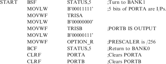
Switch scanning
Design a circuit so that if a switch is pressed a corresponding LED will light. i.e.
If SW0 is Hi, (logic1 or Set) then LED0 is on.
If SW0 is Low, (logic 0 or Clear) then LED0 is off.
The circuit diagram for this is shown if Figure 5.5 and the corresponding flowchart in Figure 5.6.
Figure 5.5 Switch scanning circuit
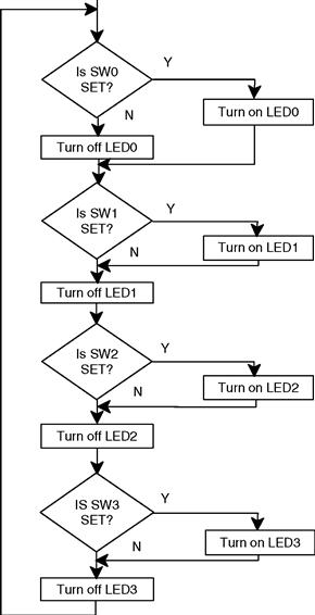
Figure 5.6 Flowchart for switch scan
The program for this switch scan is:
;SWSCAN.ASM using 16F84 and 32kHz crystal.
;EQUATES SECTION
;**********************************************************
| LIST | P = 16F84 | ;We are using the 16F84. |
| ORG | 0 | ;0 is the start address. |
| GOTO | START | ;goto start! |
;**********************************************************
;Configuration Bits
| __CONFIG H’3FF0’ | ;selects LP oscillator, WDT off, PUT on, |
| ;Code Protection disabled. |
;*****************************************************
;CONFIGURATION SECTION.
;*********************************************************
;Program starts now.
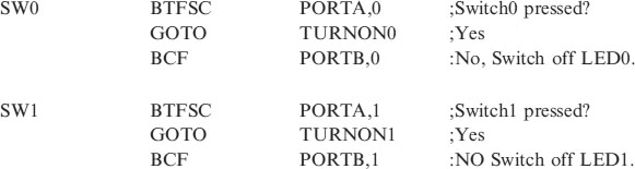
How does it work?
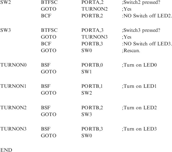
• SW0 is checked first with the instruction BTFSC PORTA,0. If the switch is closed when the program is executing this line then we GOTO TURNON0. That is the program jumps to the label TURNON0 which turns on LED0 and then jumps the program back to check SW1 at, of course, the label, SW1.
• SW1 is then checked in the same manner and then SW2 and SW3.
Suppose we press the switch when the program is not looking at it. The program lines are being executed at ¼ of the clock frequency i.e. 32,768Hz that is 8192 lines a second. The program will always catch you!
Try modifying the program so that the switches can flash 4 different routines e.g. SW0 flashes all lights on and off 5 times for 1 second.
Control application – a hot air blower
The preceding section outlined how to monitor inputs by looking at them in turn. This application will ‘read’ all the bits on the port at once, because we will be concerned with particular combinations of inputs rather than individual ones.
The bits on the Input Port will be 0s or 1s and we can treat this binary pattern like any other number in a file.
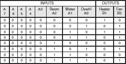
Consider a controller for a hot air radiator. When the water is warm the fan will blow the warm air into the room. The heater and fan are controlled by 3 temperature sensors: (a) a room temperature sensor, (b) a boiler water temperature sensor and (c) a safety overheating sensor. The truth table for the system is shown in Table 5.1, where a 1 means hot and a 0 means cold for the sensors.
Table 5.1 Truth table for the hot air system
The block diagram for the system is shown in Figure 5.7.
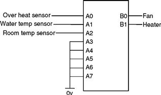
Figure 5.7 Block diagram for the hot air system
Note A3, A4, A5, A6 and A7 are inputs and need to be connected to 0v. Do not leave them floating – you would not know if they were 0 or 1! Even though they are not being used they are still being read. NB. The inputs A5, A6 and A7 do not exist on the 16F84.
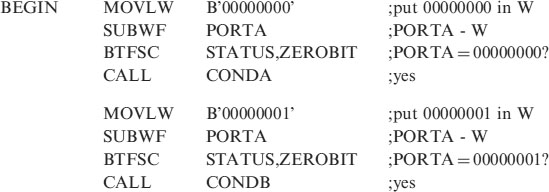
There are 8 input conditions from our 3 sensors. So all 8 must be checked to determine which condition is true.
Consider the first condition A2 = A1 = A0 = 0, i.e. PORTA reads 0000 0000. How do we know that PORTA is 0000 0000? We do not have an instruction which says “is PORTA equal to 0000 0000” or any other value for that matter. So we need to look at our 35 instructions and come up with a way of finding out what is the binary value of PORTA.
We check for this condition by subtracting 00000000 from it, if the answer is zero then PORTA reads 00000000. I.e. 0000 0000 − 0000 0000 = 0 (obviously). But how do we subtract the two numbers and how do we know if the answer is zero?
This is a very important piece of programming so read the next few lines carefully.
• We first of all read PORTA into the W register with the instruction MOVF PORTA,W that moves the data, (setting of the switches, 1s or 0s), into W.
• We then subtract the number we looking for in this case 00000000 from W.
• We then need to know if the answer to this subtraction is zero. If it is then the value on PORTA was 00000000. If the answer is not zero then the value of the data on PORTA was not zero.
• So is the answer zero Yes or No? The answer is held in a register called the Status Register, in bit 2 of this register, called the zero bit. If the zero bit, called a flag is 1, it is indicating that the statement is true the calculation was zero. If the zero bit is 0 that indicates the statement is false the answer was not zero.
• We test the zero bit in the status register just like we tested the bit on the switch connected to PORTA at the start of this chapter. We use the command BTFSC and the instruction BTFSC STATUS, ZEROBIT. If the zero bit is clear we skip the next instruction if it is set we have a match and do not skip.
The code for this is:
| MOVLW | B’00000000’ | ;put 000000 in W |
| SUBWF | PORTA | ;subtract W from PORTA |
| BTFSC | STATUS, ZEROBIT | ;PORTA = 00000000? |
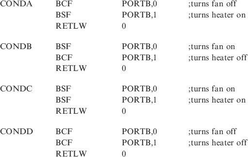
| CALL | CONDA | ;yes |
CONDA is short for condition A where we require the heater on and the fan off.
• To check for A2 = A1 = 0 and A0 = 1 we subtract 00000001. To check for the next condition A2 = 0, A1 = 1, A0 = 0 we subtract 00000010, and so on for the other 5 conditions.
| MOVLW | B’00000001’ | ;put 00000001 in W |
| SUBWF | PORTA | ;subtract W from PORTA |
| BTFSS | STATUS, ZEROBIT | ;PORTA = 00000001? |
| CALL | CONDB | ;yes |
| etc. |
The opcode for this program CONTROL.ASM is:
;SUBROUTINE SECTION.
;*********************************************************
;Program starts now.
Notice that the SUBROUTINE SECTION needs to be changed to include the conditions, CONDA, CONDB, CONDC and CONDD. The DELAY subroutines are not required in this example.
The program can be checked by using switches for the input sensors and LEDs for the outputs.
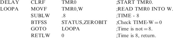
There is more than one way of skinning a cat, another way of writing this program is shown in Chapter 8, in the section on look up tables.