
7
Keypad scanning
There are no new instructions used in this chapter
Keypads are an excellent way of entering data into the microcontroller. The keys are usually numbered but they could be labeled as function keys for example in a remote control handset in a TV to adjust the sound or colour etc.
As well as remote controls, keypads find applications in burglar alarms, door entry systems, calculators, microwave ovens etc. So there are no shortage of applications for this section.
Keypads are usually arranged in a matrix format to reduce the number of I/O connections.
A 12 key keypad is arranged in a 3 × 4 format requiring 7 connections.
A 16 key keypad is arranged in a 4 × 4 format requiring 8 connections.
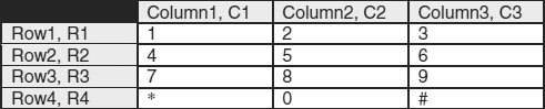
Consider the 12 key keypad. This is arranged in 3 columns and 4 rows as shown in Table 7.1. There are 7 connections to the keypad – C1, C2, C3, R1, R2, R3 and R4.
Table 7.1 12 Key keypad
This connection to the micro is shown in Figure 7.1.
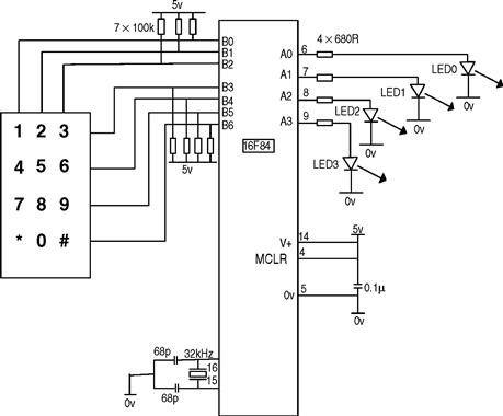
Figure 7.1 Keypad connection to the microcontroller
The keypad works in the following way:
If for example key 6 is pressed then B2 will be joined to B4. For key 1 B0 would be joined to B3 etc. as shown in Figure 7.1.
The micro would set B0 low and scan B3, B4, B5 and B6 for a low to see if keys 1, 4, 7 or * had been pressed.
The micro would then set B1 low and scan B3, B4, B5 and B6 for a low to see if keys 2, 5, 8 or 0 had been pressed.
Finally B2 would be set low and B3, B4, B5 and B6 scanned for a low to see if keys 3, 6, 9 or # had been pressed.
Programming example for the keypad
As a programming example when key 1 is pressed display a binary 1 on PORTA, when key 2 is pressed display a binary 2 on PORTA etc.
Key 0 displays 10. Key * displays 11. Key # displays 12.
This program could be used as a training aid for decimal to binary conversion.
The flowchart is shown in Figure 7.2.
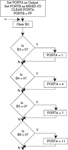
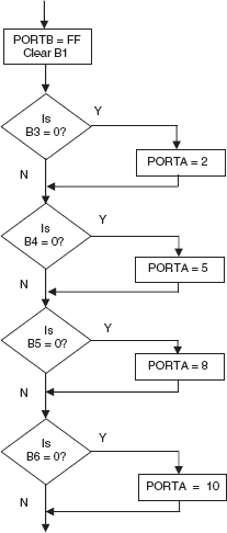
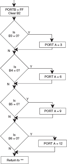
Figure 7.2 Keypad scanning flowchart
The program listing for the Keypad example for the 16F84 is shown below but can be used with any ‘suitable’ microcontroller using the appropriate header.
N.B. PORTA has been configured as an output port and PORTB has been configured with 3 outputs and 5 inputs, so the header will require modifying as shown.
PORTB has internal pull up resistors so that the resistors connected to PORTB in Figure 7.1 are not required.
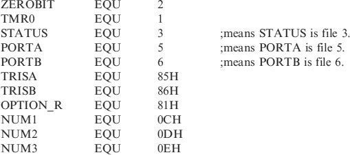
;EQUATES SECTION
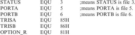
;*********************************************************
| LIST | P = 16F84 | ;we are using the 16F84. |
| ORG | 0 | ;the start address in memory is 0 |
| GOTO | START | ;goto start! |
;*********************************************************
;CONFIGURATION BITS
| __Config H′3FF0′ | ;selects LP Oscillator, WDT off, |
| ;Put on, | |
| ;code protection disabled. |
;*********************************************************
;CONFIGURATION SECTION
;*********************************************************
;Program starts now.
How does the program work?
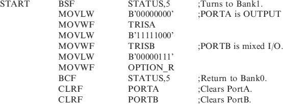
Port configuration
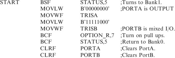
The first thing to note about the keypad circuit is that the PORTA pins are being used as outputs. On PORTB, pins B0, B1 and B2 are outputs and B3, B4, B5 and B6 are inputs. So PORTB is a mixture of inputs and outputs. The HEADER84.ASM program has to be modified to change to this new configuration.
To change PORTA to an output port, the following two lines are used in the Configuration Section:
| MOVLW | B′00000000′ | ;PORTA is OUTPUT |
| MOVWF | TRISA |
To configure PORTB as a mixed input and output port the following two lines are used in the Configuration Section:
| MOVLW | B′11111000′ | |
| MOVWF | TRISB | ;PORTB is mixed I/O. B0,B1,B2 are O/P. |
Scanning routine
The scanning routine looks at each individual key in turn to see if one is being pressed. Because it can do this so quickly it will notice we have pressed a key even if we press it quickly.
The scanning routine first of all looks at the keys in column1 i.e. 1, 4, 7 and *. It does this by setting B0 low, B1 and B2 high. If a 1 is pressed the B3 will be low, if a 1 is not pressed then B3 will be high. Because pressing a 1 connects B0 and B3.
Similarly if 4 is pressed B4 will be low if not B4 will be high.
In other words when we set B0 low if any of the keys in column1 are pressed then the corresponding input to the microcontroller will go low and the program will output the binary number equivalent of the key that has been pressed.
If none of the keys in column1 are pressed then we move onto column2.
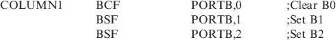
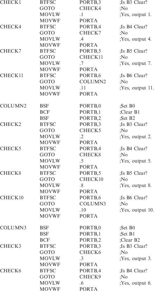
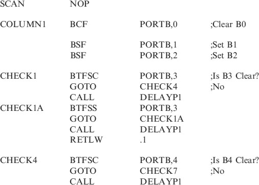
The code for scanning column1 is as follows:
These 3 lines set up PORTB with B0 = 0, B1 = 1 and B2 = 1.

These next 4 lines test input B3 to see if it clear if it is then a 1 is placed on PORTA, then the program continues. If B3 is set then we proceed to check to see if key 4 has been pressed, with CHECK4.
These next 4 lines test input B4 to see if it clear if it is then a 4 is placed on PORTA, then the program continues. If B4 is set then we proceed to check to see if key 7 has been pressed, with CHECK7.
These next 4 lines test input B5 to see if it clear if it is then a 7 is placed on PORTA, then the program continues. If B5 is set then we proceed to Check to see if key * has been pressed, with CHECK11.
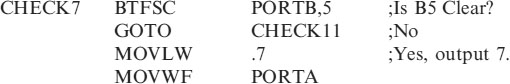
These next 4 lines test input B6 to see if it clear if it is then an 11 is placed on PORTA, then the program continues. If B5 is set then we proceed to check the keys in column2, with COLUMN2.
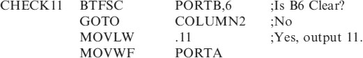
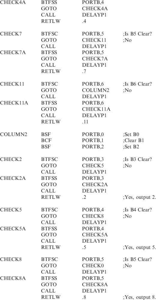
These 3 lines set up PORTB with B0 = 1, B1 = 0 and B2 = 1.
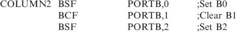
We then check to see if key2 has been pressed by testing to see if B3 is clear, if it is then a 2 is placed on PORTA and the program continues. If B3 is set then we proceed with CHECK5. This code is:
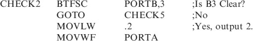
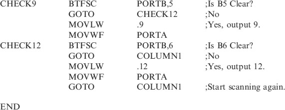
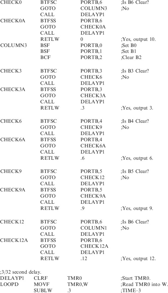
The program continues in the same manner checking 5, 8 and 10 (0). Then moving onto column3 to check for 3, 6, 9 and 12 (#). After completing the scan the program then goes back to continue the scan again.
It takes about 45 lines of code to complete a scan of the keypad. With a 32,768Hz crystal the lines of code are executed at ¼ of this speed i.e. 8192 lines per second. So the scan time is 45/8192 = 5.5ms. This is why no matter how quickly you press the key the microcontroller will be able to detect it.
Security code
Probably one of the most useful applications of a keypad is to enter a code to turn something on and off such as a burglar alarm or door entry system.
In the following program KEYS3.ASM the sub-routine SCAN, scans the keypad, waits for a key to be pressed, waits 0.1 seconds for the bouncing to stop, waits for the key to be released, waits 0.1 seconds for the bouncing to stop and then returns with the key number in W which can then be transferred into a file.
This is then used as a security code to turn on an LED (PORTA,0) when 3 digits (137) have been pressed and turn the LED off again when the same 3 digits are pressed. You can of course use any 3 digits.
;KEYS3.ASM
;EQUATES SECTION
;*********************************************************
| LIST | P = 16F84 | ;we are using the 16F84. |
| ORG | 0 | ;the start address in memory is 0 |
| GOTO | START | ;goto start! |
;*********************************************************
;SUB-ROUTINE SECTION
;**********************************************************
;*****************************************************
How does the program work?
The ports are configured as in the previous code KEYPAD.ASM.
The KEYS3.ASM program looks for the first key press and then it compares the number pressed with the required number stored in a user file called NUM1. It then looks for the second key to be pressed. But because the microcontroller is so quick, the first number could be stored and the program looks for the second number, but our finger is still pressing the first number.
Anti-bounce routine
Also when a mechanical key is pressed or released it does not make or break cleanly, it bounces around. If the micro is allowed too, it is fast enough to see these bounces as key presses so we must slow it down.
• We look first of all for the switch to be pressed.
• Then wait 0.1 seconds for the switch to stop bouncing.
• We then wait for the switch to be released.
• We then wait 0.1 seconds for the bouncing to stop before continuing.
The switch has then been pressed and released indicating one action.
The 0.1 second delay is written in the Header as DELAYP1.
Scan routine
The scan routine used in KEYS3.ASM is written into the subroutine.
When called it waits for a key to be pressed and then returns with the number just pressed in W. It can be copied and used as a subroutine in any program using a keypad.
• The scan routine checks for key presses as in the previous example KEYPAD.ASM, Column1 checks for the numbers 1, 4, 7 and 11 being pressed in turn.
• If the 1 is not pressed then the routine goes on to check for a 4.
• If the 1 is pressed then the routine waits 0.1 second for the bouncing to stop.
• The program then waits for the key to be released.
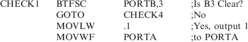
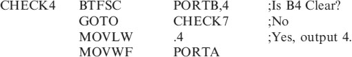
Code for CHECK1:
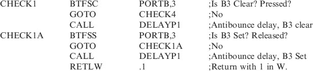
If numbers 4, 7 or 11 are pressed the routine will return with the corresponding value in W.
If no numbers in column1 are pressed then the scan routine continues on to column2 and column3. If no keys are pressed then the routine loops back to the start of the scan routine to continue checking.
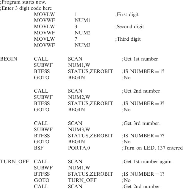
Storing the code
The code i.e. 137 is stored in the files NUM1, NUM2, NUM3 with the following code:
| MOVLW | 1 | ;First digit |
| MOVWF | NUM1 | |
| MOVLW | 3 | ;Second digit |
| MOVWF | NUM2 | |
| MOVLW | 7 | ;Third digit |
| MOVWF | NUM3 |
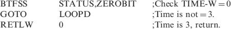
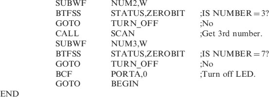
Checking for the correct code
• We first of all CALL SCAN to collect the first digit, which returns with the number pressed in W.
• We then subtract the value of W from the first digit of our code stored in NUM1 with:
This means SUBtract W from the File NUM1. The (,W) stores the result of the subtraction in W. Without (,W) the result would have been stored in NUM1 and the value changed!
• We then check to see if NUM1 and W are equal, i.e. a correct match. In this case the zerobit in the status register would be set. Indicating the result NUM1−W = zero. This is done with:
• With a correct first press we then carry on checking for a second and if correct a third press to match the correct code.
BSF PORTA,0
Notice that if you enter an incorrect digit you return to BEGIN or TURN_OFF. If you forget what key you have pressed then press an incorrect one and start again.
You could of course modify this program by adding a fourth digit to the program then turn on the LED. In which case you use another user file called NUM4. You could of course use a different code for switching off the output.
You can also beep a buzzer for half a second to give yourself an audible feedback that you had pressed a button.
As an extra security measure you could wait for a couple of seconds if an incorrect key had been pressed, or wait for 2 minutes if three wrong numbers had been entered.
The keypad routine opens up many different circuit applications.
The SCAN routine can be copied and then pasted into any program using the keypad. Then when you CALL SCAN the program will return with the number pressed in W for you to do with it as you wish.