Chapter Goal: Use the Perspective Grid and Perspective Selections tools to create sides of shapes that appear in an image with the correct perspective. I will complete this chapter by demonstrating how to use the 3D non-destructive effects with 2D objects and text.
In this chapter, we will look at some tools that we can use to add perspective to your artwork even if you are not a professional artist. Then we will look at and compare classic and new 3D features that have been added to Illustrator, and how these can be used to enhance the look of shapes and text.
We’ll also finish off the landscape project we have been working on throughout many of the Illustrator chapters in this book.
Finally, we will be making a quick overview of the Graph tools and discover how they can be used to create a basic 3D infographic that could be used in a magazine or on a website to inform people on a specific topic.
You can find the projects for this chapter in the Chapter 13 folder.
Perspective Grid & Perspective Selection Tools

Toolbars panel Perspective Grid tool and Perspective Selection tool with Active Plane widget
In Photoshop you can work with Perspective Warp Smart Object filters and the vanishing point filter to create a box with a warped design. You can refer to the books mentioned in the introduction if this topic is of interest to you.
In Chapter 8, we used Object ➤ Envelope Distort ➤ Make with Top Object to warp a pattern over another vector object. However, there are other situations where you might want to draw a landscape or a cityscape in perspective for a comic book or a poster, but you are just not sure how to begin. This can be tricky for the beginner artist, especially if they have not taken a lot of art classes on perspective or have difficulty visualizing perspective on the Artboard while working at a computer.
Let’s practice that now.
Project: Skyscraper City Scene
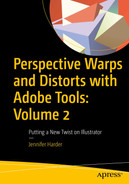
Background of illustration visible in Layers panel, and City layer active
This file has three layers. The Background with a horizon, sky, and moon; the City layer, on which you are going to use the Perspective Grid tool; and a Clouds layer for which the visibility is turned off, as it is not required in this part of the project. To create the start of the city, select the City layer.

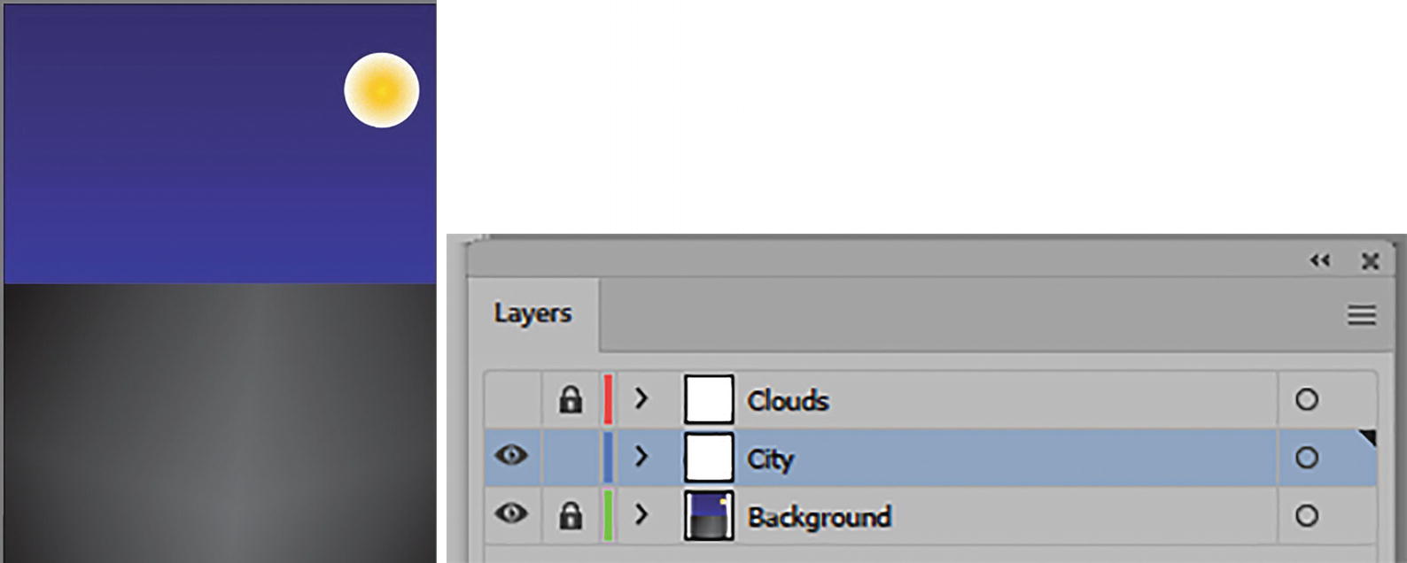
Toolbars panel Perspective Grid tool and Perspective Selection tool
Default two-point perspective with Active Plane widget
View ➤ Perspective Grid
The grid, before you start to draw, can be altered in several ways. It is always good to set up the grid and decide on a perspective before you start to draw so that you do not have to redraw parts of your artwork later.
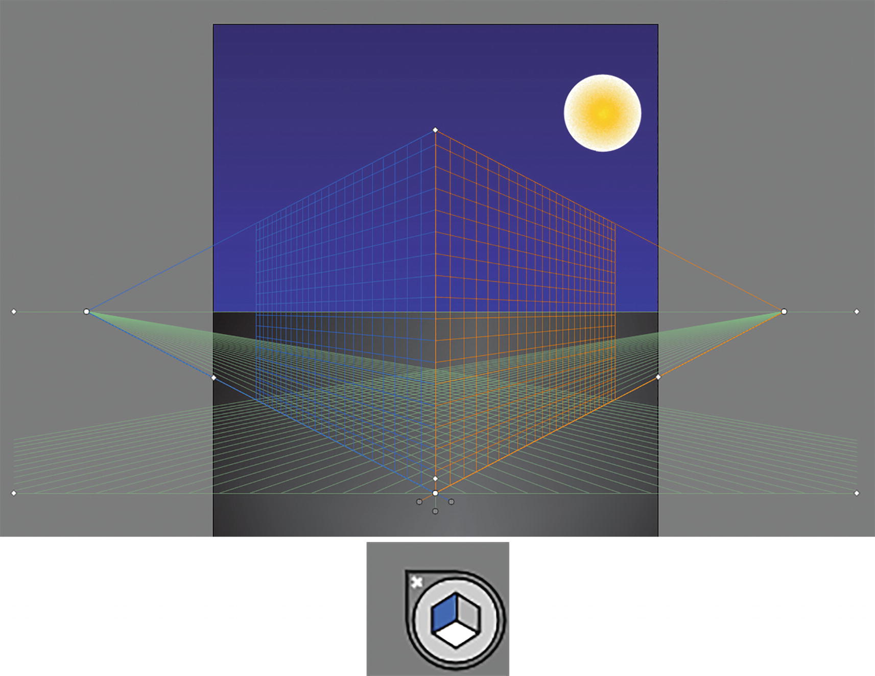
Options in the View ➤ Perspective Grid menu
Here you can choose to Hide the grid after working with it (Shift + Ctrl/CMD + I), or go to View ➤ Perspective Grid ➤ Show Grid if it is not visible.
Show Rulers: Specifically for the Perspective Grid.
In this case you want to keep Snap to Grid selected, as you will need it with the Smart Guides to assist you as you draw. It allows parts of your path to snap to the grid lines.
Lock Grid: You can lock the grid to keep parts of it from being altered or moved as you use the Perspective Grid tool. Then only the visibility of the grid and plane position of the left, right and horizontal grid can be moved using their lower handles which we will look at shortly in the custom grid section of the chapter.
Lock Station Point: When enabled ensures that the left and right sides of the grid’s vanishing point move together. In this case, I kept these settings unlocked so that both vanishing points can be moved separately, as well as the station point, which we will look at in a moment.

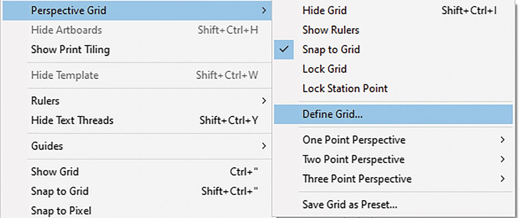
Define Perspective Grid dialog box
While in the dialog box, you can create and save preset custom perspective grid settings for the following:
Type: The type of grid you want to use; from the list choose One Point, Two Point, or Three Point Perspective. Refer to Figure 13-6.
Units: The settings by default are set to Points, but you can change this to Inches, Centimeters, or Pixels. Refer to Figure 13-6.

Define Perspective Grid dialog box Scale options

Define Perspective Grid dialog box, Gridline every 30 pt setting

Define Perspective Grid dialog box, with Viewing Angle, Viewing Distance, Horizon Height, and Third Vanishing Point options
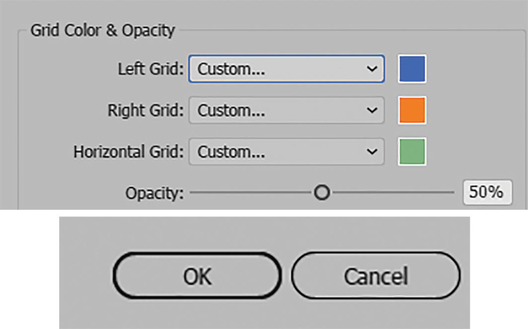
Define Perspective Grid dialog box Grid Color and Opacity options, and OK and Cancel buttons

View ➤ Perspective Grid perspective options
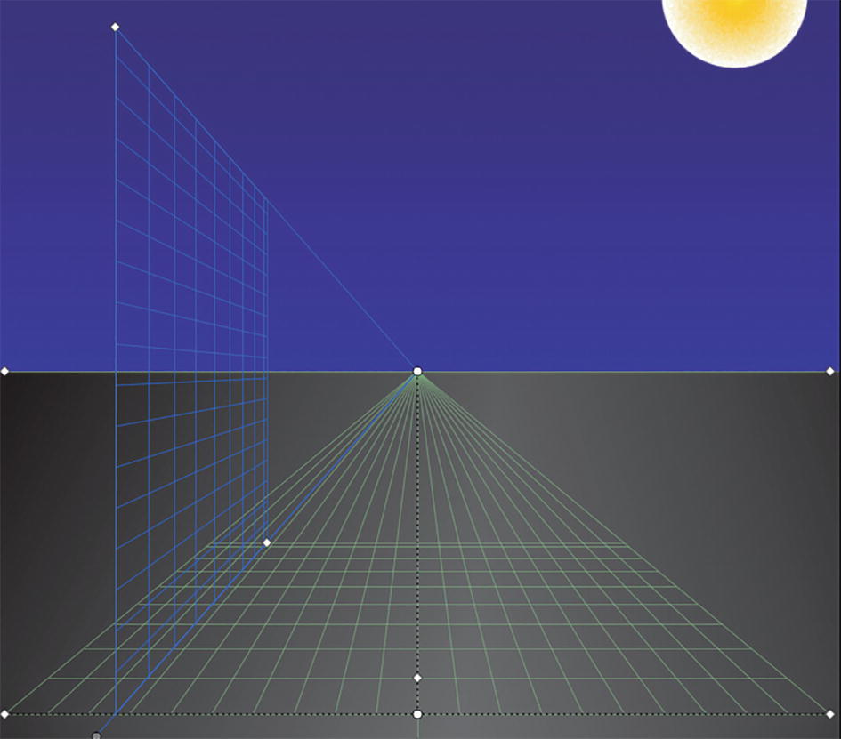
One Point Perspective grid
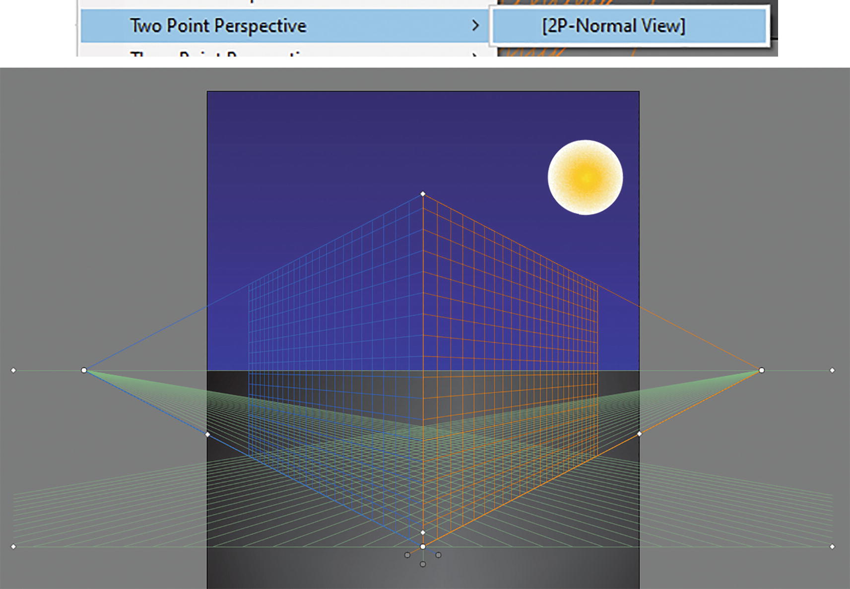
Two Point Perspective grid and option

Three Point Perspective grid and option

Set Two Point Perspective option for this project
Making a Custom Grid
While in this project we are going to use the preset grid, alternatively, you could move the various handles on the grid to create your own custom perspective grid.
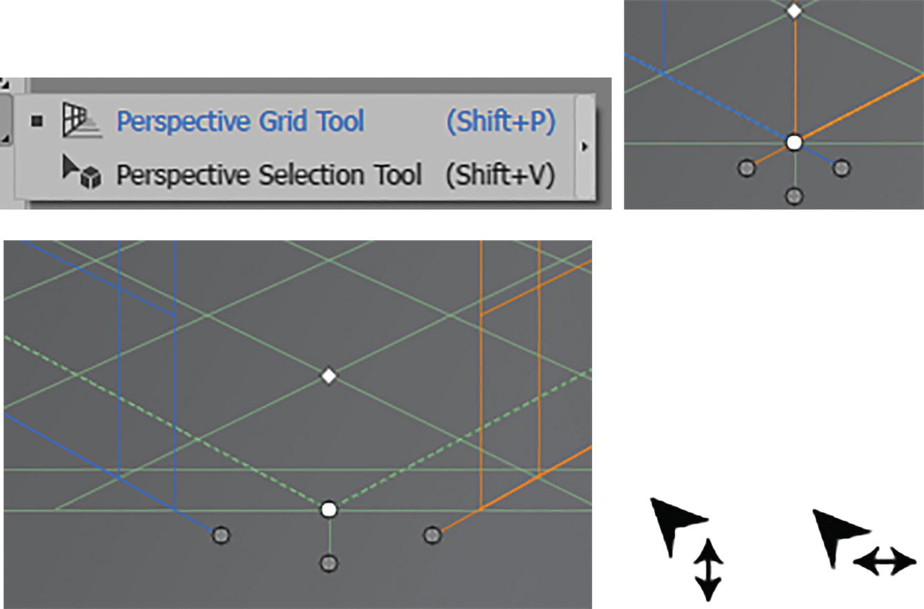
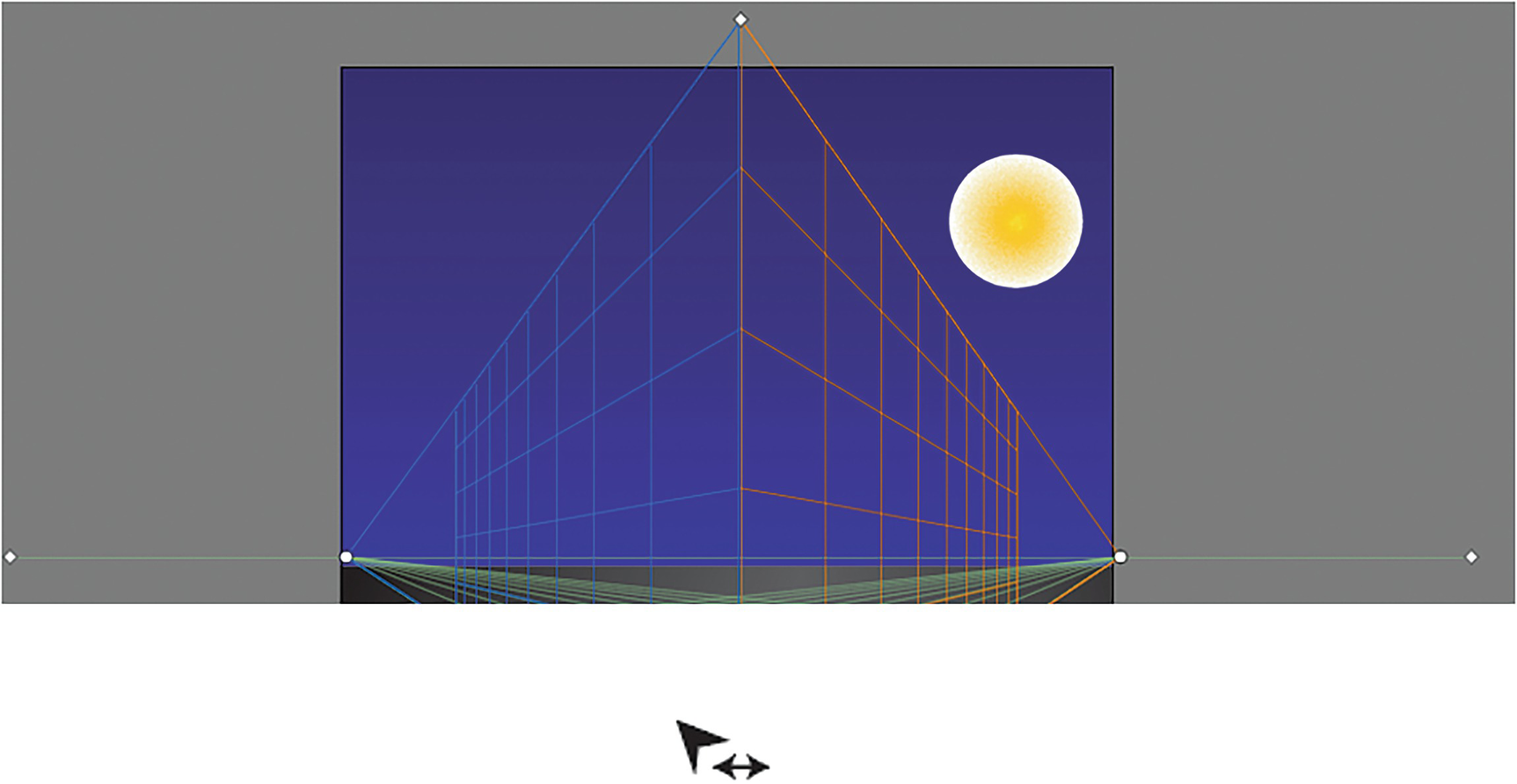
Perspective Grid tool, Perspective Selection tool, and moving lower handles and how the cursor changes when you move the handles of a grid plane control
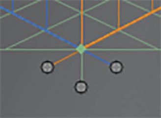
How the Grid Plane Handles appear when you use the Perspective Selection tool
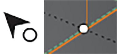
How the cursor changes when you move the ruler origin point
How the cursor changes when you move the diamond handle to adjust the grid cell size

How the cursor changes when you move the diamond handles to control the extent of the grid
How the cursor changes when you move the top vertical grid extent
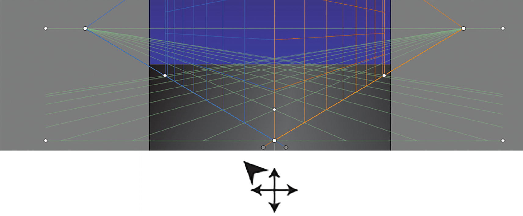
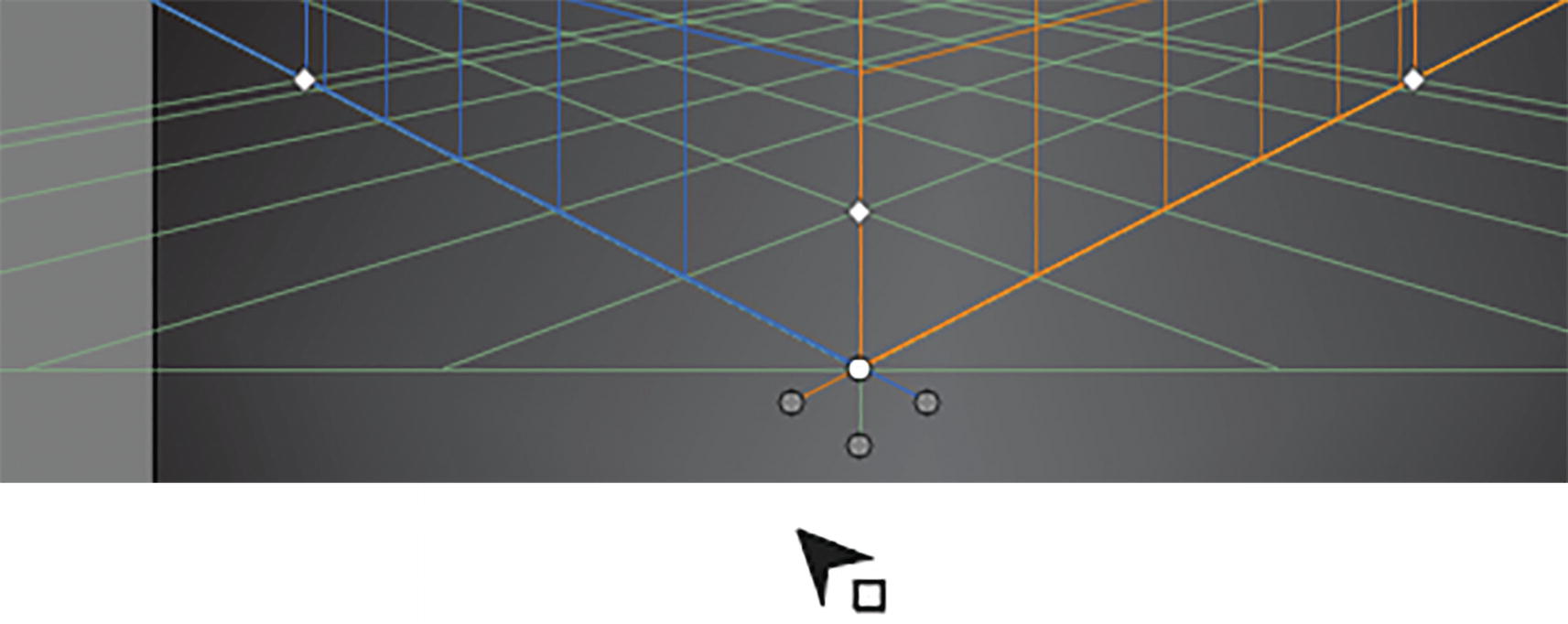
How the cursor changes when you move the lower diamond handles to move the grid

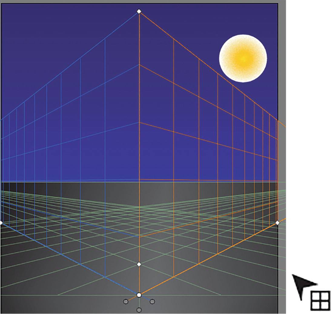
How the cursor changes when you move the upper diamond handles to adjust the horizon height
How the cursor changes when you move the middle circle handles to adjust the left and right sides of the grid with the horizon
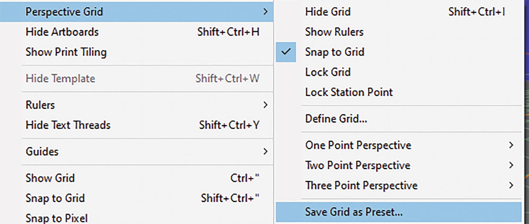
View ➤ Perspective Grid ➤ Save Grid as Preset option

Save Grid as Preset dialog box and new saved grid option added to the sub-menu
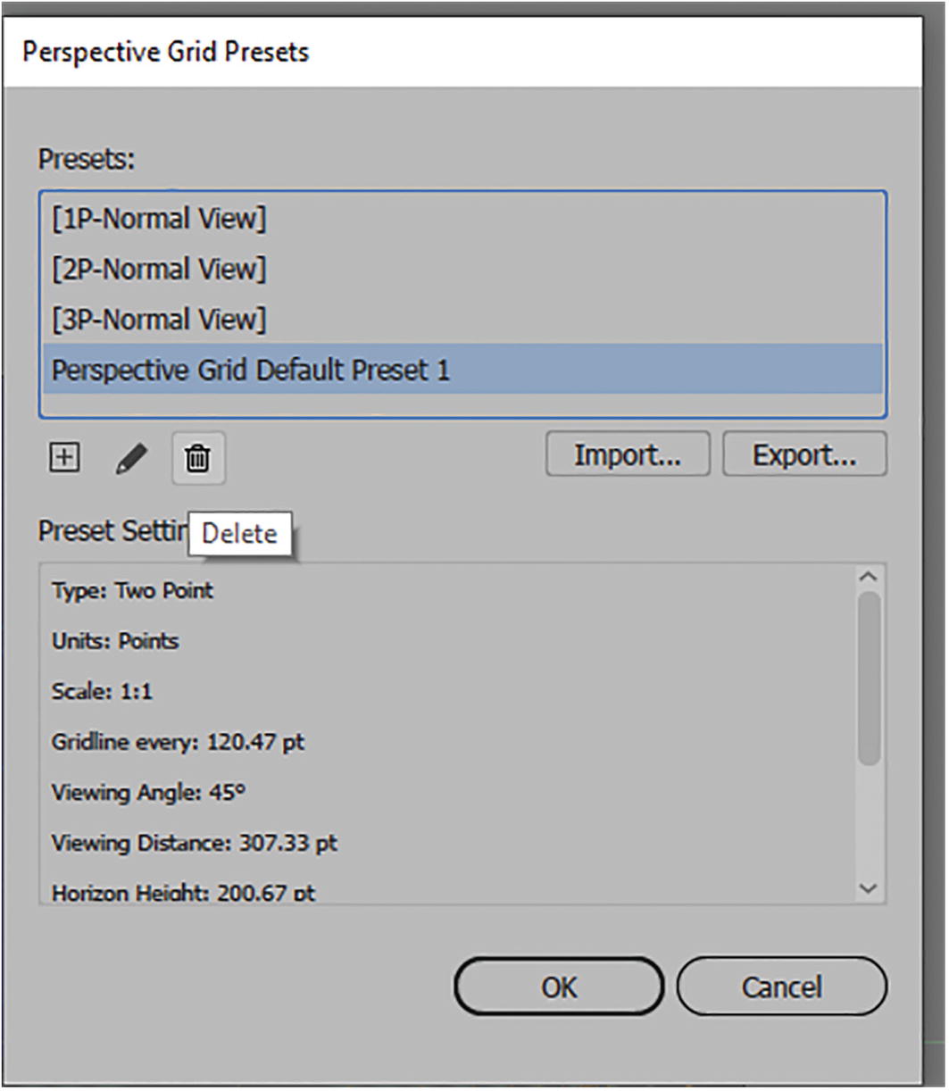
Perspective Grid Presets dialog box
In this dialog box, you can also add a new preset, and edit, import, and export grid presets for other users. You cannot delete the default presets. You can also see a summary of the preset settings for each preset. Refer to Figure 13-27.

Current default of two point perspective for project
Drawing on the Perspective Grid

Rectangle tool and Two Point Perspective grid on Artboard

Active Plan widget with left grid selected

Use the Rectangle tool to draw in perspective on the plane
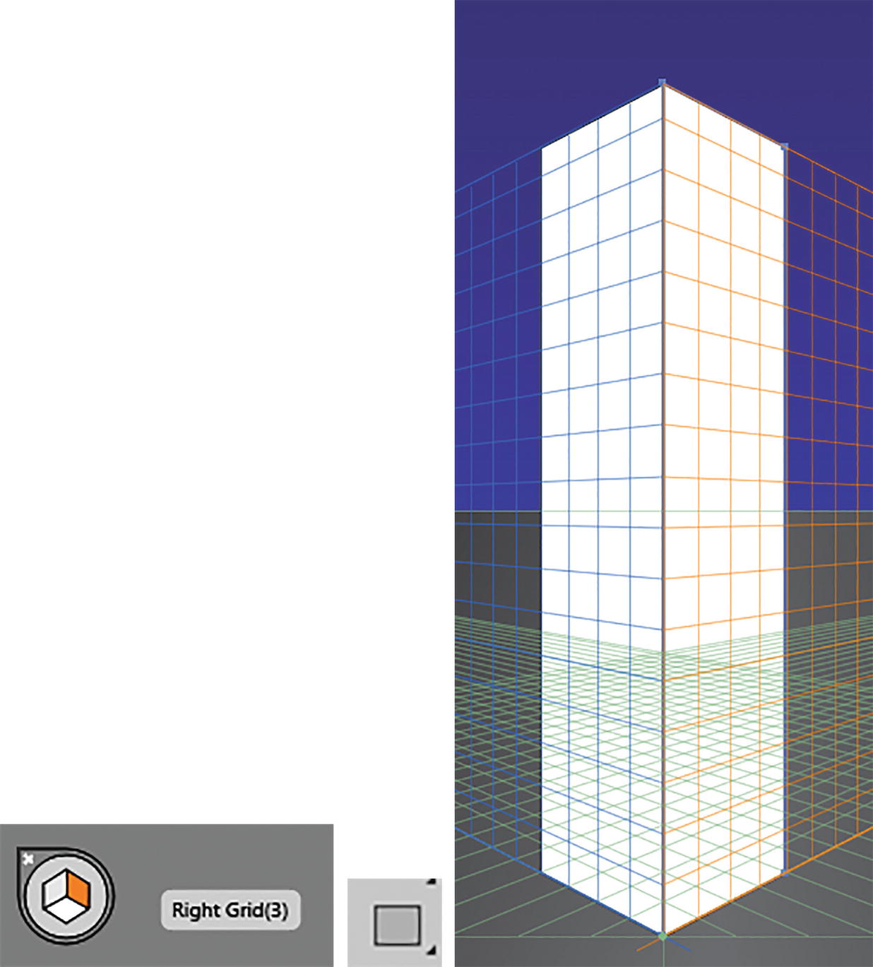
Active Plan widget with right grid selected, Rectangle tool, and drawing in perspective on the plane

Use the Selection tool and Control panel to recolor your rectangles
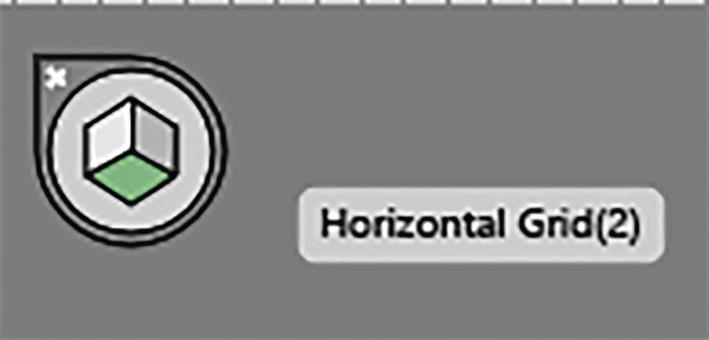
Active Plan widget with horizontal grid selected
Use the Rectangle tool to draw on the horizontal grid

Active Plan widget with no active grid selected

Perspective Grid tool and Perspective Selection tool Grid Options dialog box
This dialog box indicates whether the Active Plane widget will be visible and where it will be placed on the screen while you work. By default, it is in the top-left.

All three grids currently intersecting

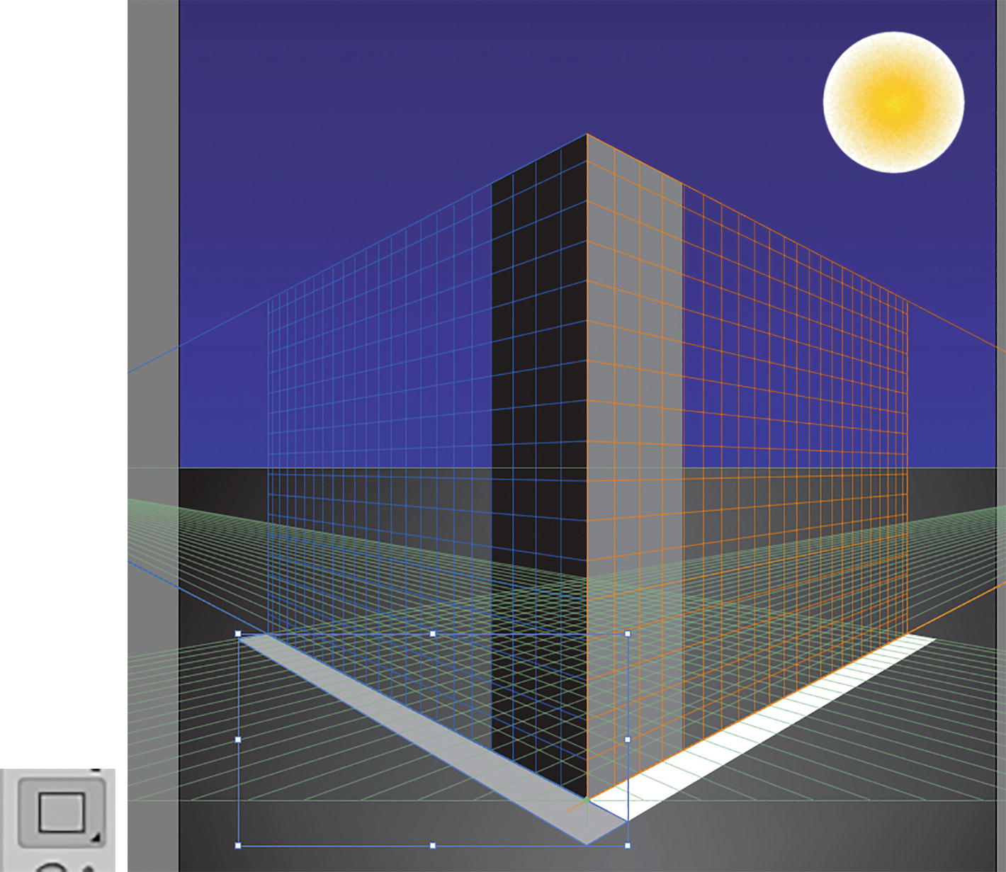
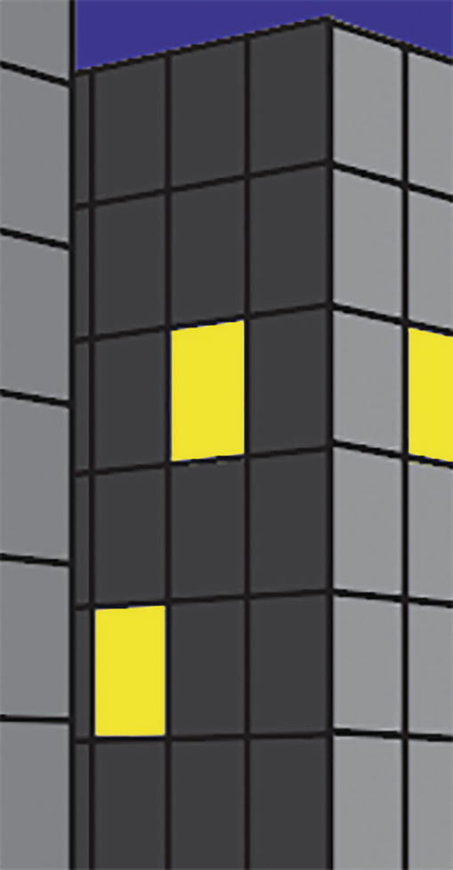
Use the Active Plane widget and Rectangle tool to draw windows on the skyscraper
Use the Selection tool to select windows and color them using the Control panel
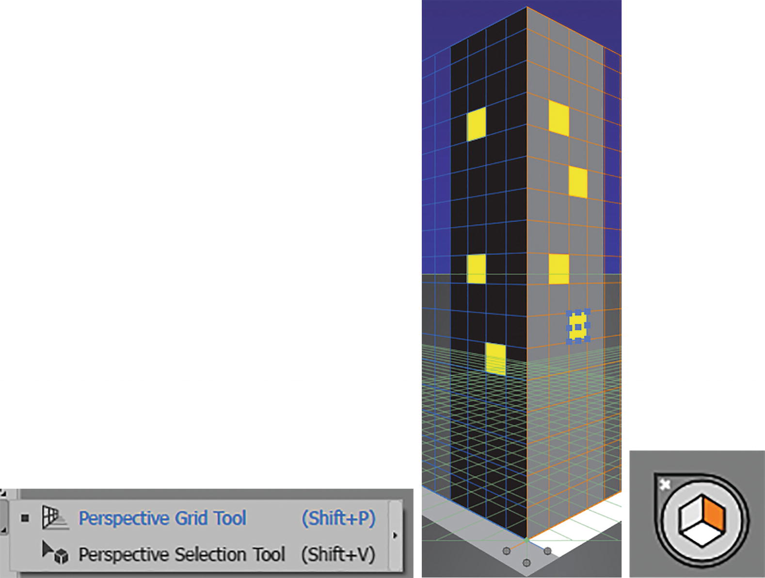
Use the Perspective Selection tool and the Active Plane widget to move a selected copy of a window to another area on the grid

Use the Perspective Selection tool and the Active Plane widget to move a selected copy of a window to another area on another grid
Left Grid: Drag + 1
Horizontal Grid: Drag + 2
Right Grid: Drag + 3
Perpendicular Movement: Drag + 5
Add the Alt/Option key to any of these combinations to copy and/or the Shift key to constrain the movement. You can also use the command Object ➤ Transform again (Ctrl/CMD + D) to repeat a similar movement on the current plane.
Use the Perspective Selection tool to scale and move objects while on the grid.
Additional options for the Perspective Selection tool can be found for the right, left, and horizontal vanishing planes when you double-click on the circle grid point handles. Refer to Figure 13-43.

Vanishing Plane dialog box for left, right, and floor (horizontal) grids
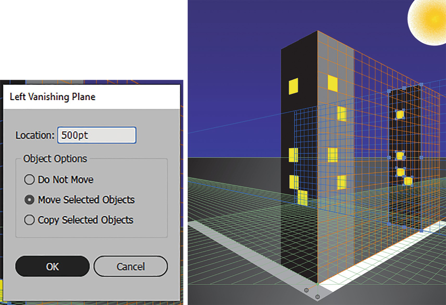
Use the grid and its dialog box to move or to copy selected objects, and a preview of how the movement would appear
If you have tried this setting, you can use Edit ➤ Undo to undo that last step or click the Cancel button in the dialog box. I left the settings at Location: 0 pt and Do Not Move.

Use the Active Plane widget and Rectangular Grid tool and its dialog box to create a grid in perspective
You might have to use different settings, depending on the size of your building and grid.

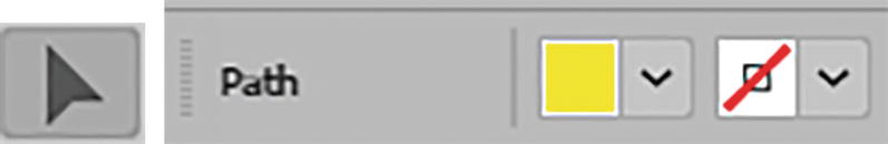
The rectangular grid on the Artboard with the Control panel settings of fill none, stroke black, 1 pt stroke weight

Use the Direct Selection tool to adjust the lines of the grid

Current window and grid setting on the right side of the building
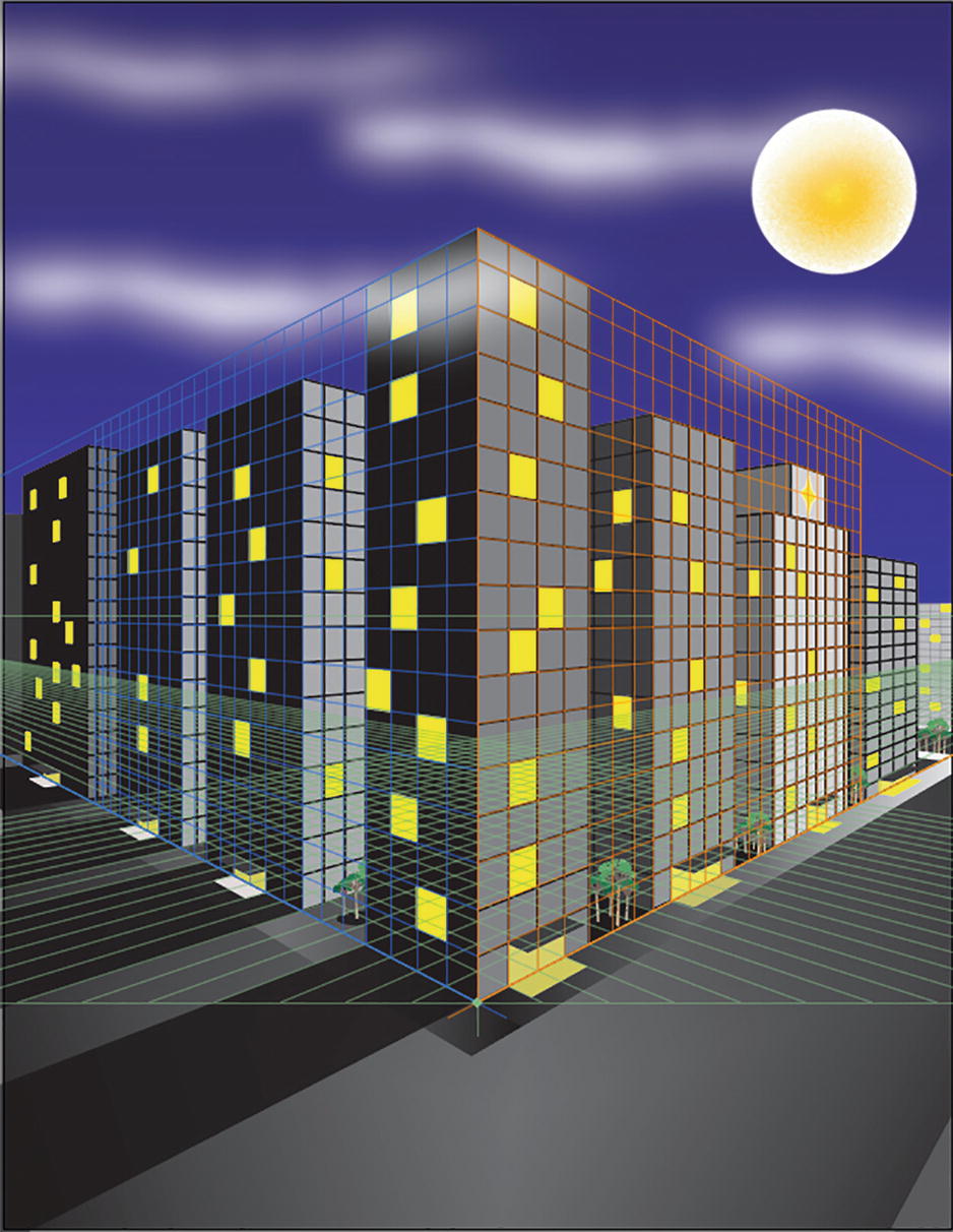
A whole city scene can be created with the Perspective Grid tool
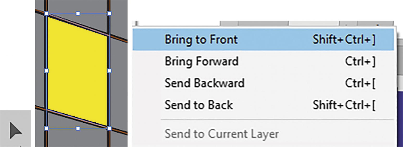
Use the Selection tool and Direct Selection tool with Object ➤ Arrange commands to move objects forward and backward on the layers
You may need to move parts of one building behind another to complete the perspective
I also added a star in perspective on the building and added awnings with my horizontal plane, as I did with sidewalks. I also added a few symbols of trees between some of the buildings. On some of the shapes I even varied the opacity to make the area appear like light was shining out of parts of the building. Refer to Figure 13-52.
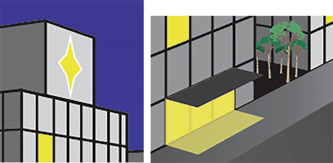
Adding details in perspective to the scene to add interest
I hope that this will get you started using the Perspective Grid tool and Perspective Selection tool. So, as you can see, working with the perspective tools allows you to create your own creative city landscape.
Additional Perspective Commands

Object ➤ Perspective commands
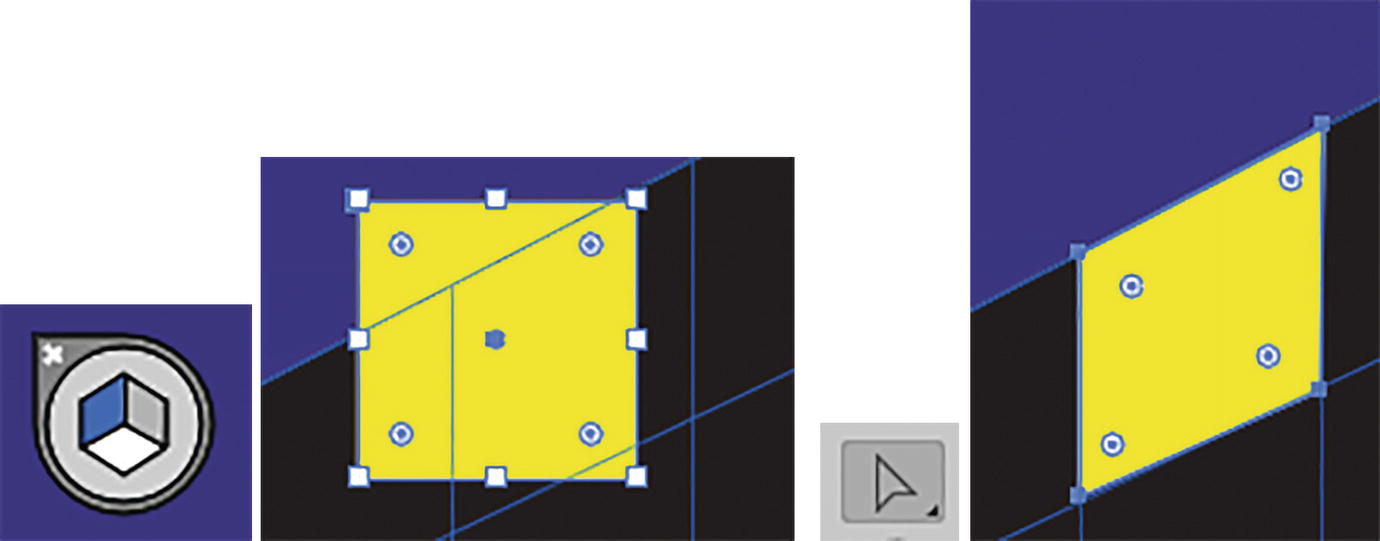
Attach your current path to the active plane and then adjust the points using the Direct Selection tool

Use the Selection tool to move the path after it is released

Choose Move the Plane to Match Object for path and use Perspective Selection tool to edit
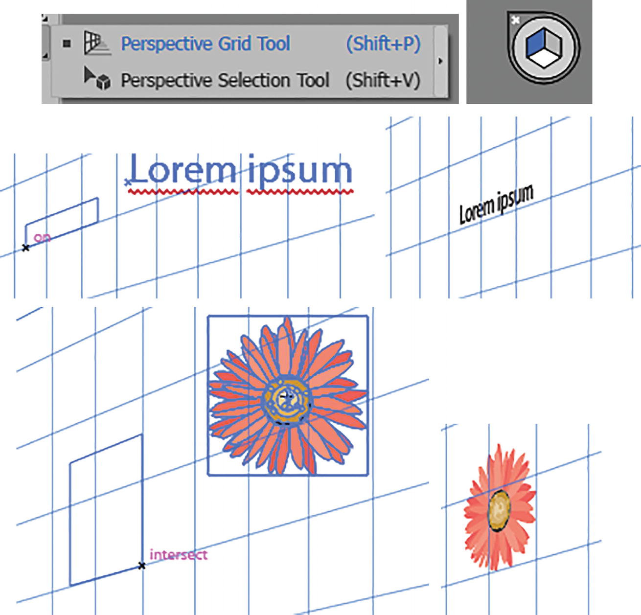
Use Perspective Selection tool and Active Plane widget to move type and symbols in perspective onto the grid

Control panel options for perspective object

Alert message when entering Symbol Editing mode in the Layers panel, exiting the Editing mode, and how it then appears in the Layers panel
Make sure to save your work at this point.
For additional details and guidance on Perspective Grid tools as well as working with symbols and type, you can visit the following links:
https://helpx.adobe.com/illustrator/using/perspective-grid.html
https://helpx.adobe.com/illustrator/using/perspective-drawing.html
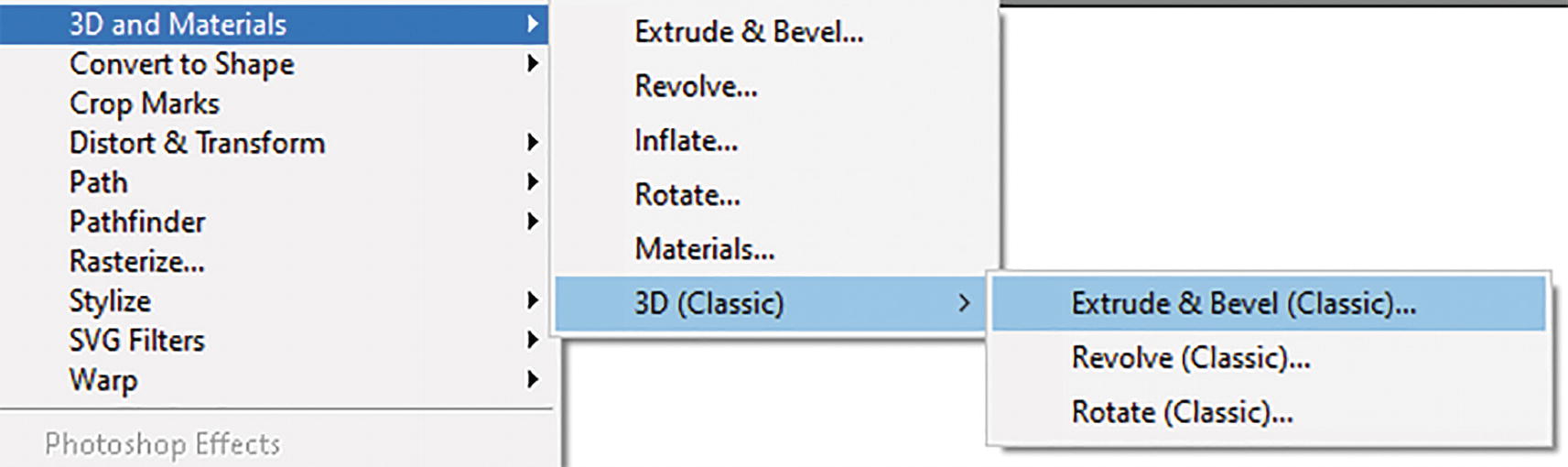
Effect ➤ 3D and Materials (3D Classic)

Effect menu settings for 3D & Materials ➤ 3D (Classic)
Extrude & Bevel (Classic)
Revolve (Classic)
Rotate (Classic)
Let’s take a brief look at each one and then look at the brand-new features and see how they compare.
Open 3D_Classic.ai if you want to work with some examples. Use File ➤ Save As to create a copy.
Rotate (Classic)
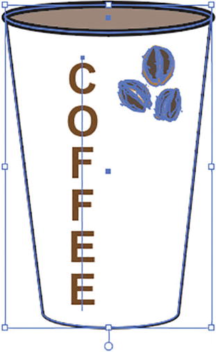
Select the group object of a coffee cup illustration

3D Rotate Options (Classic) dialog box

Rotate Options (Classic) dialog box position settings
Alternatively, you can set your own custom rotation.
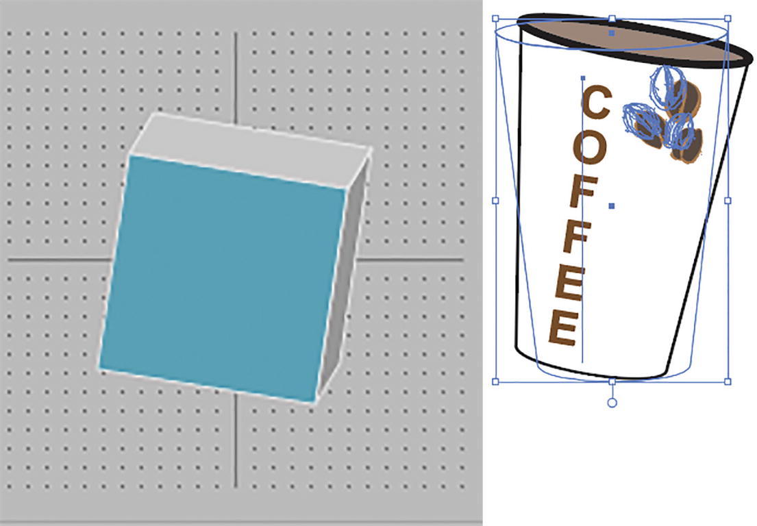
Rotate Options (Classic) dialog box rotation cube that allows you to rotate the Illustration
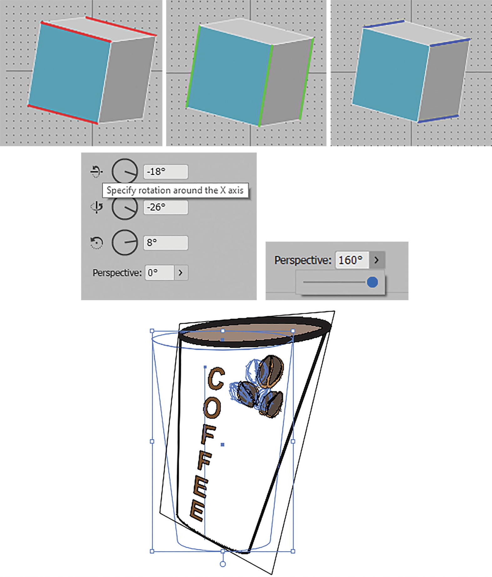
The cube has three axes—X, Y, and Z—which relate to the text boxes in the dialog box, and you can also adjust the perspective angle
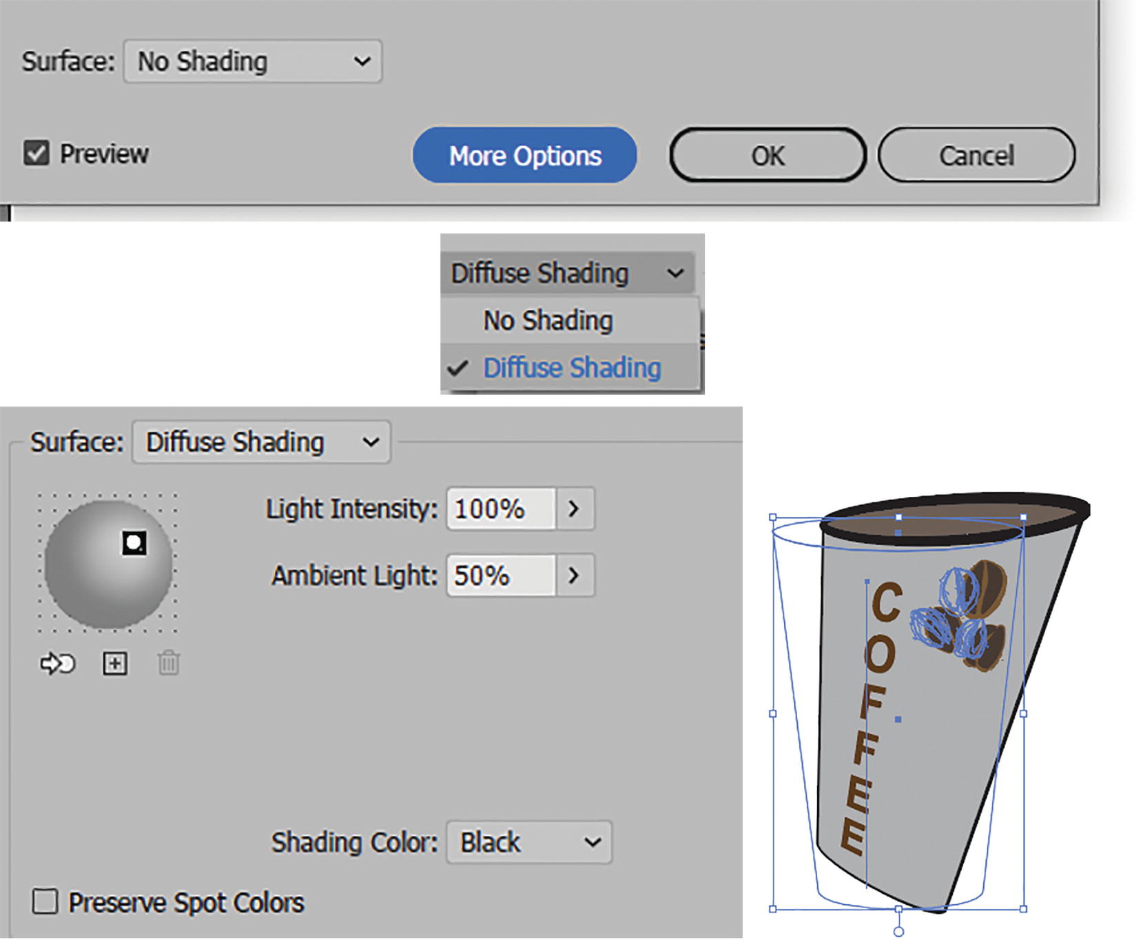
Rotate Options (Classic) dialog box Surface settings changed from No Shading to Diffuse Shading, and effect on cup
Light Intenisty specifies the brightness of the selected light on the preview sphere (0%–100%).
The ambient lighting can appear like an overall light, covering the object, or a spotlight, depending on the intensity of the ambient light (0%–100%) you choose, and can gray or brighten the overall object if there are no shadow areas. It controls the brightness of all surfaces uniformly. By default, it is set to 50%.

Rotate Options (Classic) dialog box set more than one spotlight and a custom shading

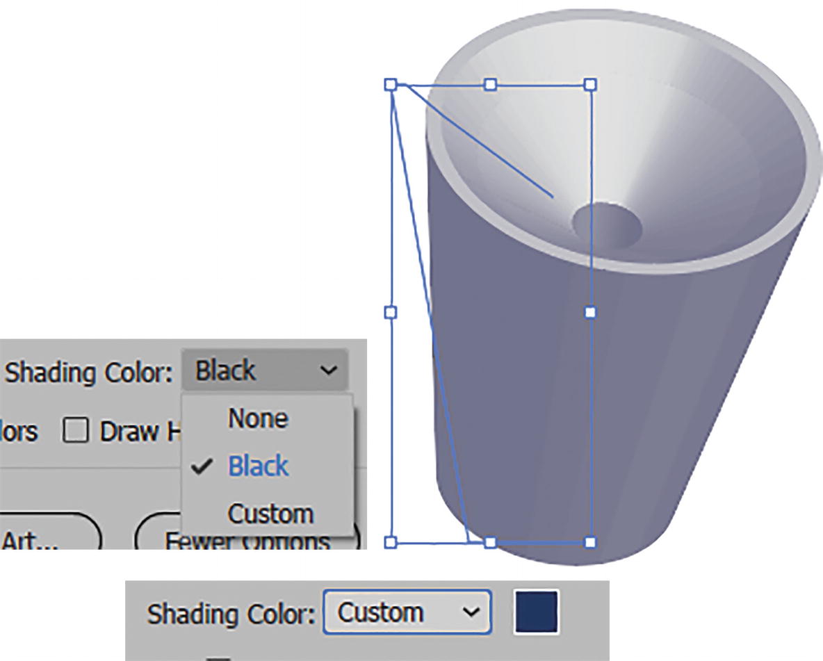
Rotate Options (Classic) dialog box set a shading color from the list and the color picker, and look at the effect on the object
Preserve Spot Colors, when enabled, will disable items that can cause the spot colors to be converted. It will also set a custom shading color back to black. By default, I left this setting disabled as we are not working with any special spot colors. Refer to Figure 13-69.
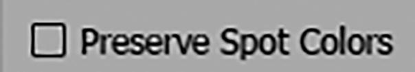
Rotate Options (Classic) dialog box, Preserve Spot Color option

Rotate Options (Classic) dialog box set back to Surface: No Shading; click OK to exit, and view the result on the object
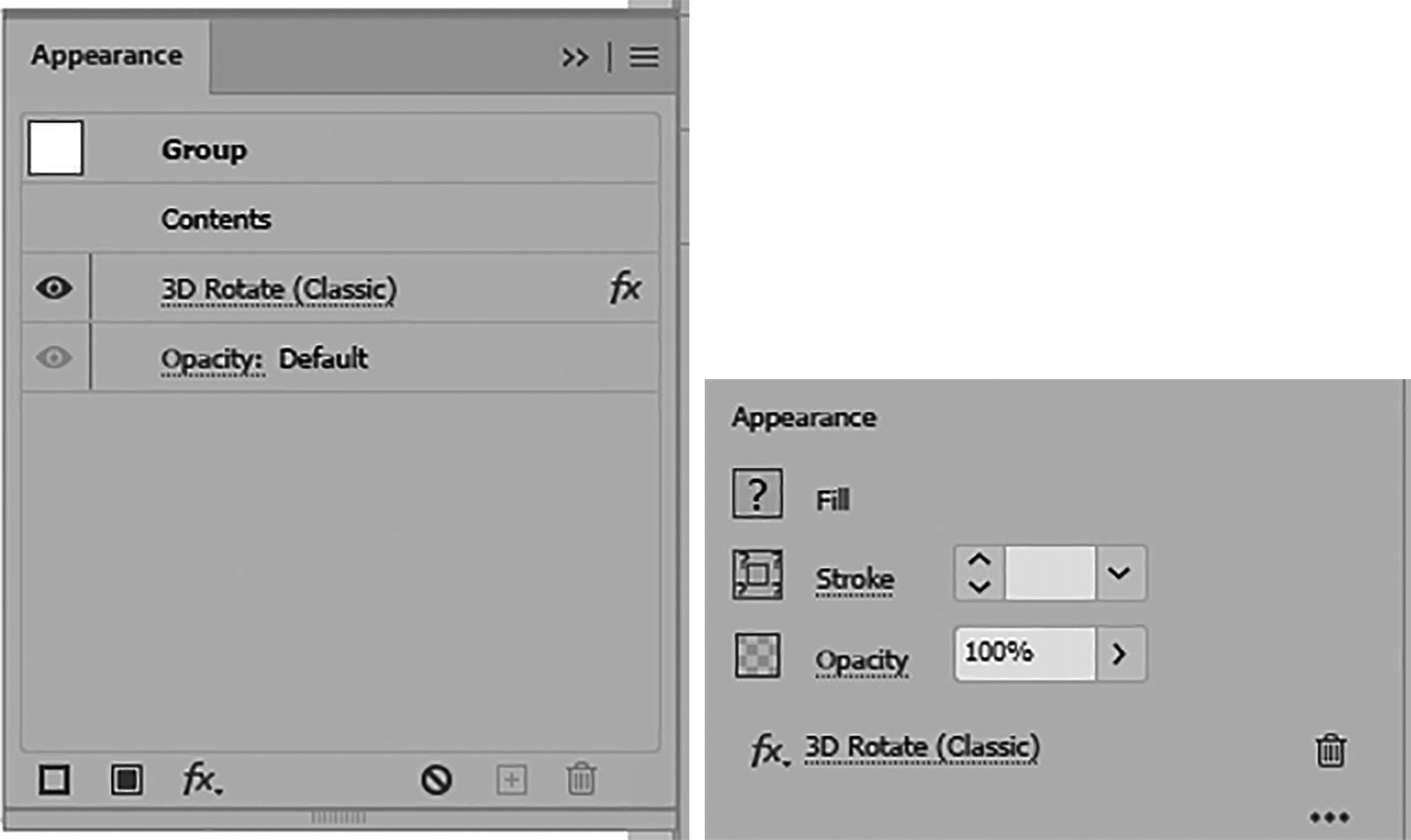
Appearance panel with effect and Properties panel with 3D Rotate (Classic)
Use Edit ➤ Undo or the History panel if you made this change so the effect is restored.
When the effect is applied to a single shape or object, while selected you can save the rotate style effect you just created in the Graphic Styles panel. You can add it to the panel by clicking New Graphic Style and then apply it when you select that effect from the panel to another selected grouped object. Refer to Figure 13-72.
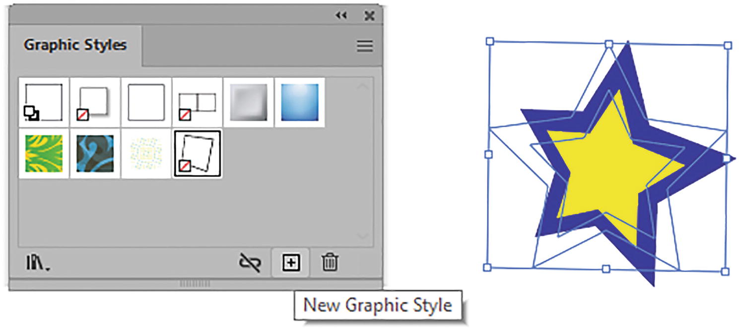
Add the effect to the Graphic Styles panel and then apply it to another grouped object

Apply a Drop Shadow effect after you have applied the 3D effect
If I no longer want the Effect to be live, I can choose Object ➤ Expand Appearance. However, make sure to Edit ➤ Undo this right away if that was not your intent and you want to keep the object live. Otherwise, keep a backup copy of the object with the effect on another layer.
Revolve (Classic)
Effect menu settings for 3D & Materials ➤ 3D (Classic) ➤ Revolve (Classic)

Set a solid color for the open path before you use Revolve (Classic)
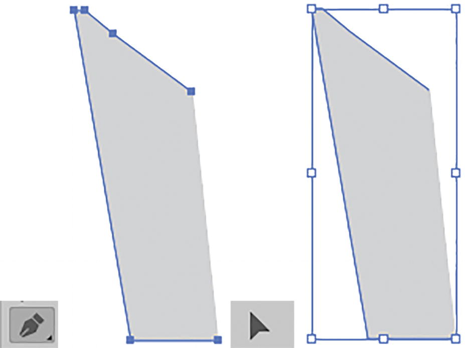
Use the Pen tool to create an open path and use the Selection tool to select it
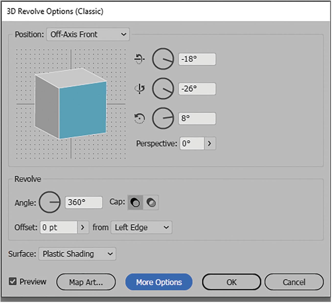
3D Revolve Options (Classic) dialog box
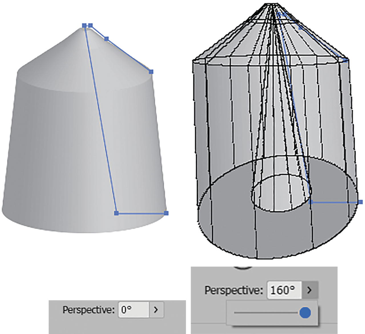
The current revolved path with the Perspective setting changed
I left the Perspective at 0°.
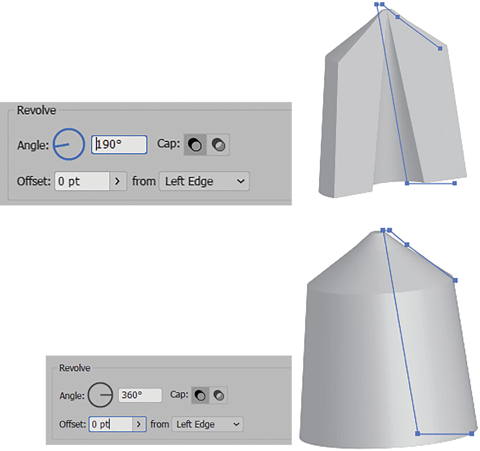
3D Revolve Options (Classic) dialog box with revolve angle and cap set
Cap: Allows you to set the cap on for a solid appearance or off for a hollow appearance. This is more apparent on some shapes. In this case I left the cap on. Refer to Figure 13-79.
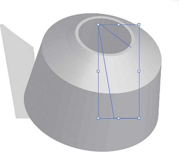
Offset of higher than 0 pt applied to 3D object
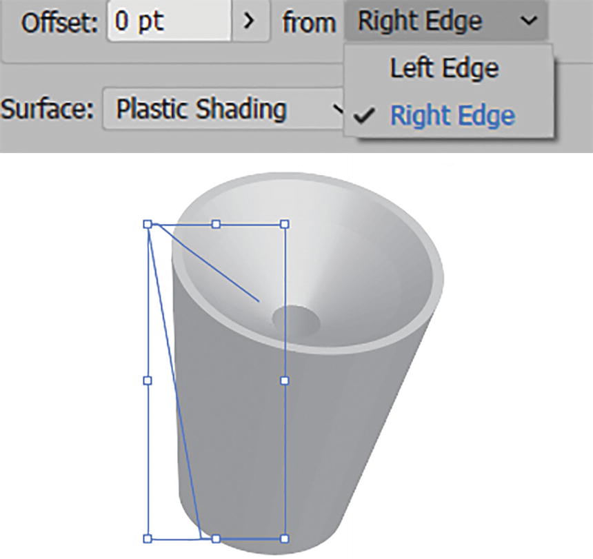
Setting the offset from Left Edge to Right Edge
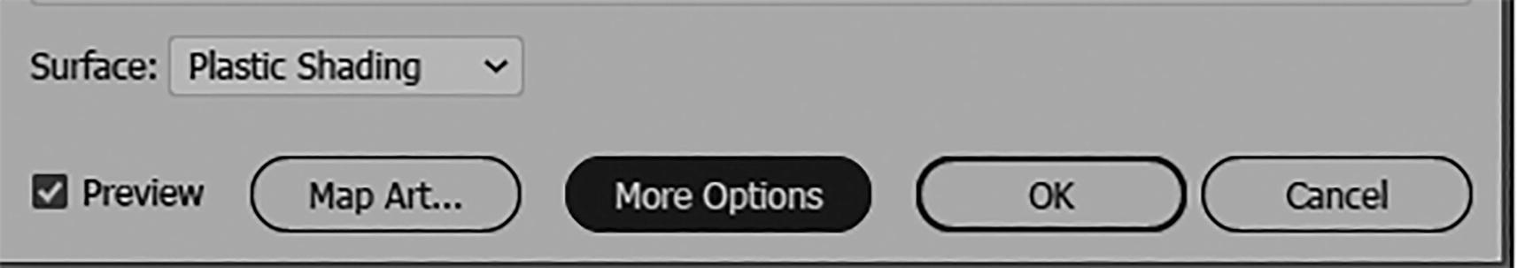
3D Revolve Options (Classic) dialog box More Options button

3D Revolve Options (Classic) dialog box, More Options for Surface settings
The Surface field is currently set to Plastic Shading. With this setting you can set the following:
Light Intensity (0%–100%): Specify the brightness of a selected light on the sphere.
Ambient Light (0%–100%): Control the brightness of all surfaces uniformly.
Highlight Intensity (0%–100%): Control how much the object reflects light.
Highlight Size (0%–100%): Specify size of highlight.
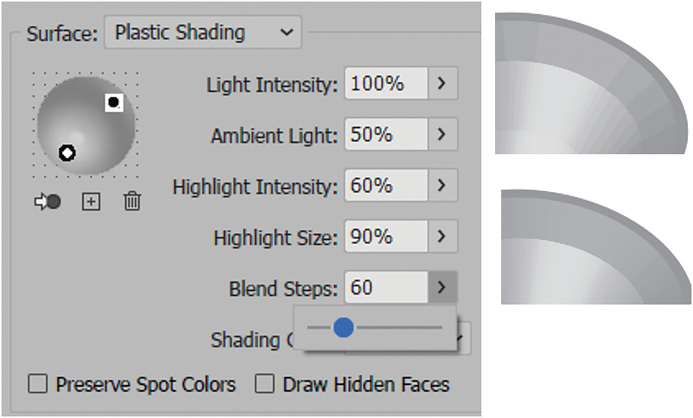
3D Revolve Options (Classic) dialog box, More Options for surface lighting and changes in Blend Steps
3D Revolve Options (Classic) dialog box, set a custom shading color
Preserve Spot Colors and Draw Hidden Faces are currently disabled.
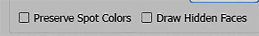
Revolve Options (Classic) dialog box options for Preserve Spot Colors and Draw Hidden Faces
Draw Hidden Faces: Specifies whether faces, hidden from view, are drawn; leaving this setting disabled speeds up the drawing process.
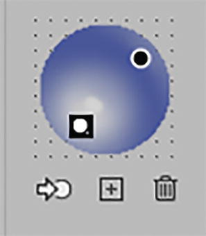
3D Revolve Options (Classic) dialog box, spotlights on sphere
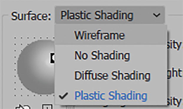
3D Revolve Options (Classic) dialog box, Surface options
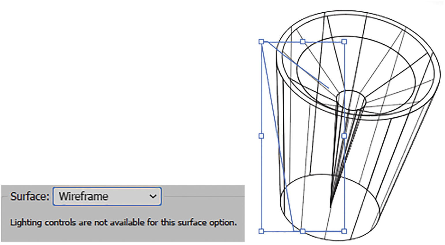
3D Revolve Options (Classic) dialog box, surface wireframe preview

3D Revolve Options (Classic) dialog box, No Shading options and preview

3D Revolve Options (Classic) dialog box Surface Defuse Shading options and preview

3D Revolve Options (Classic) dialog box Surface options set back to Plastic Shading
Map Art

3D Revolve Options (Classic) dialog box, Map Art button
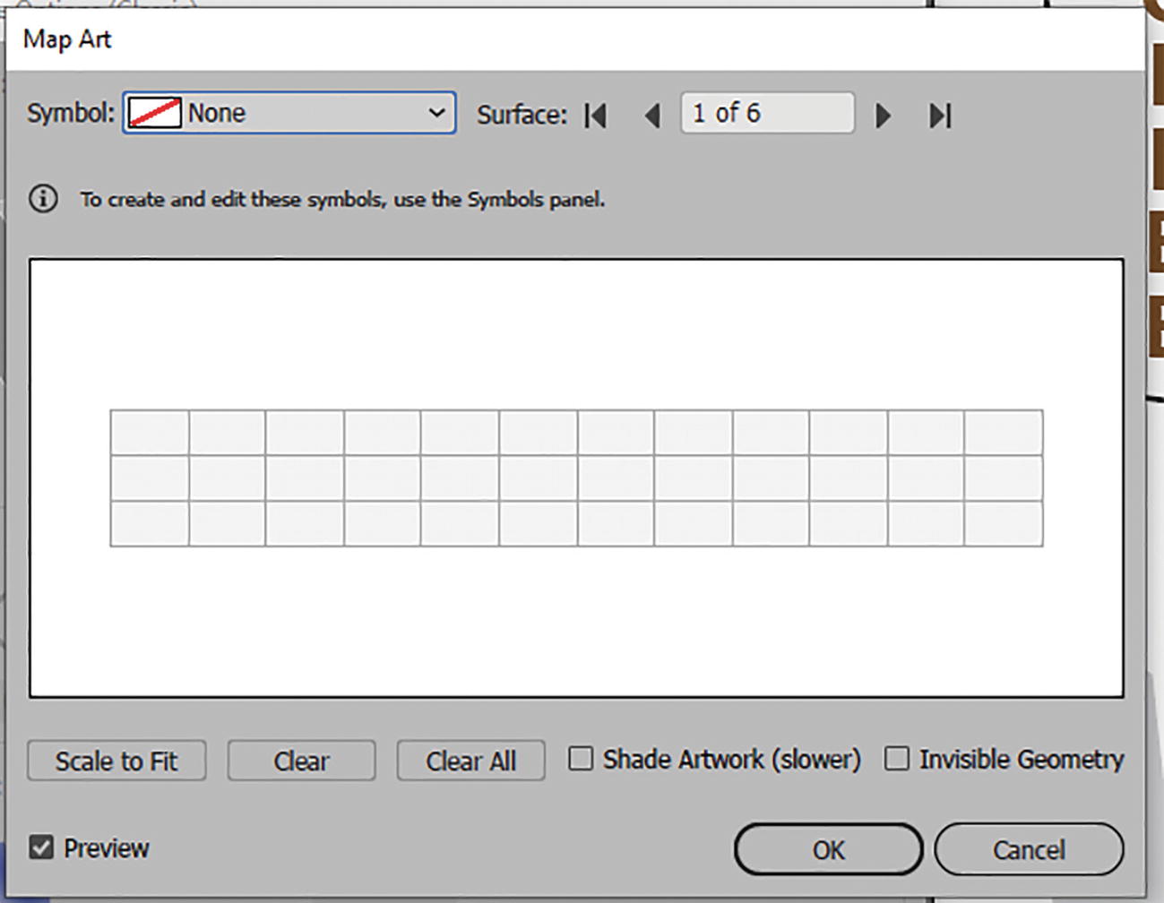
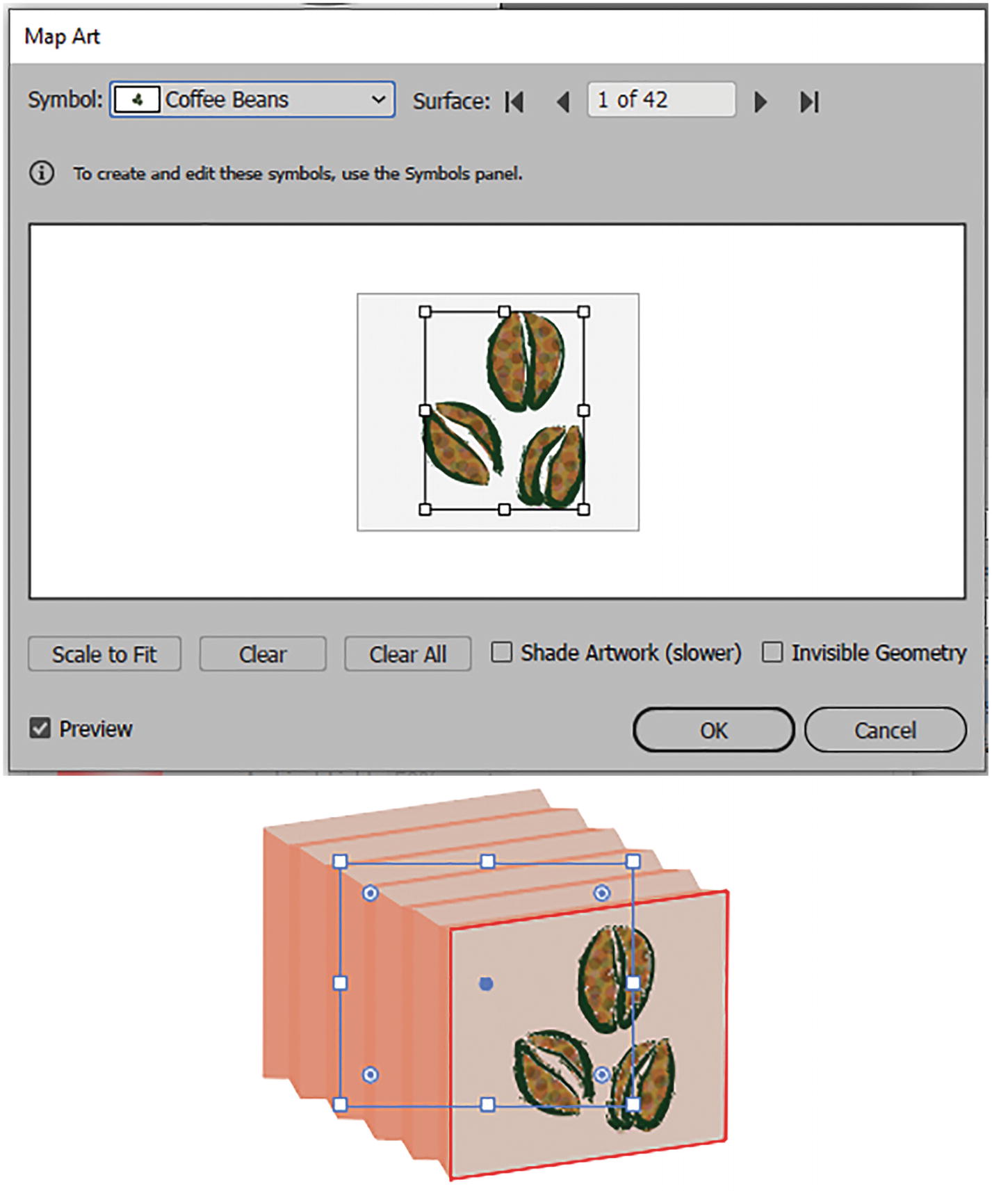
Map Art dialog box

Map Art dialog box, setting the symbol for the one of the object’s faces

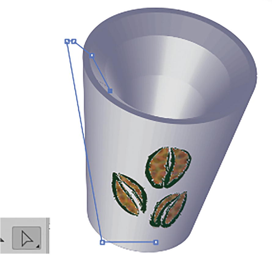
Map Art dialog box move the art on the surface to the correct location
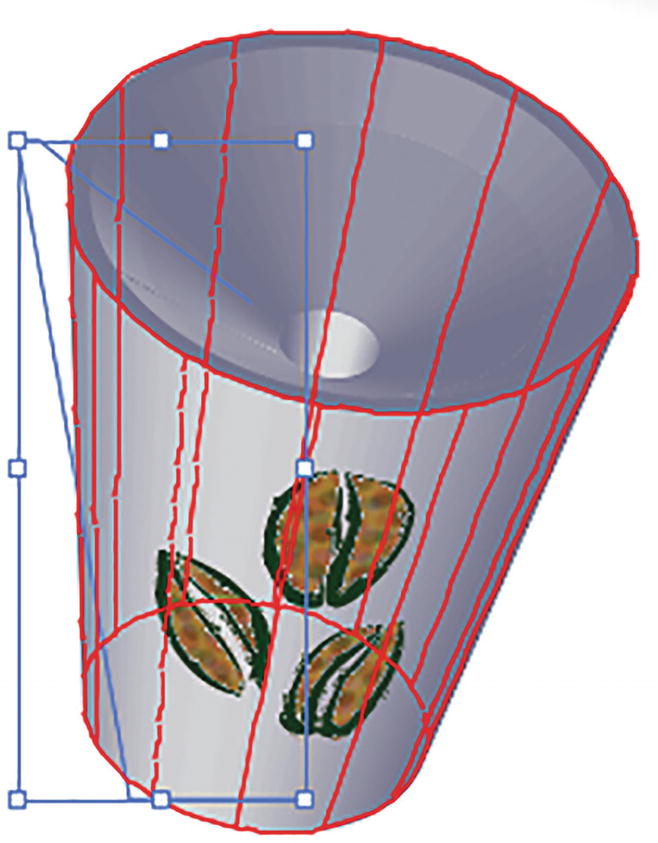
Object with Map Art preview

Map Art dialog box settings for art to scale, or clear from the Map Art dialog box

Map Art dialog box with art set to Scale to Fit and then cleared and added again to the face
Other options in this area include the following:

Map Art dialog box with Shade Artwork (Slower) option enabled
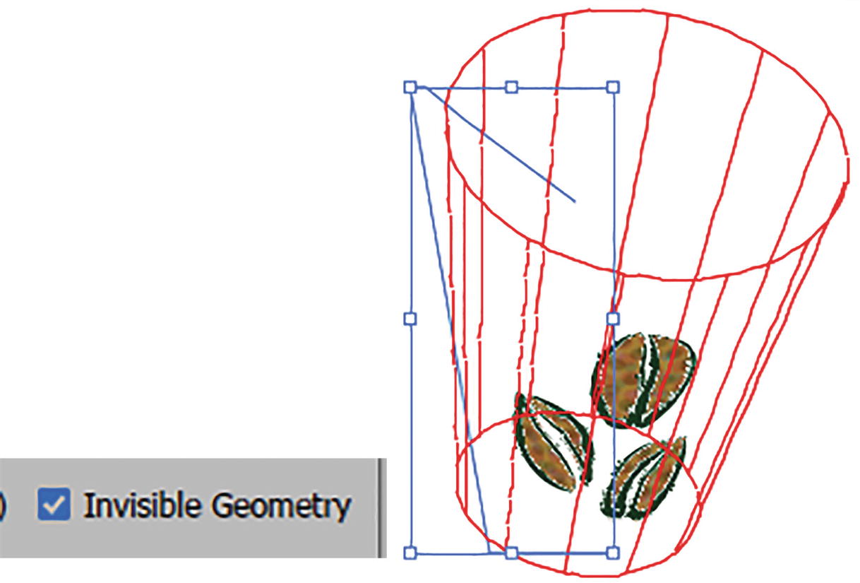
Map Art dialog box with Invisible Geometry option enabled
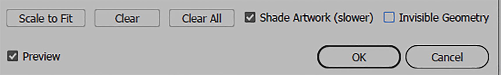
Map Art dialog box with Shade Artwork (Slower) option enabled, and click OK

Click OK to exit the 3D Revolve Options (Classic) dialog box and view result

Object with settings in the Appearance panel, and it can be added to the Graphic Style panel
Adjust the object’s path with the Direct Selection tool
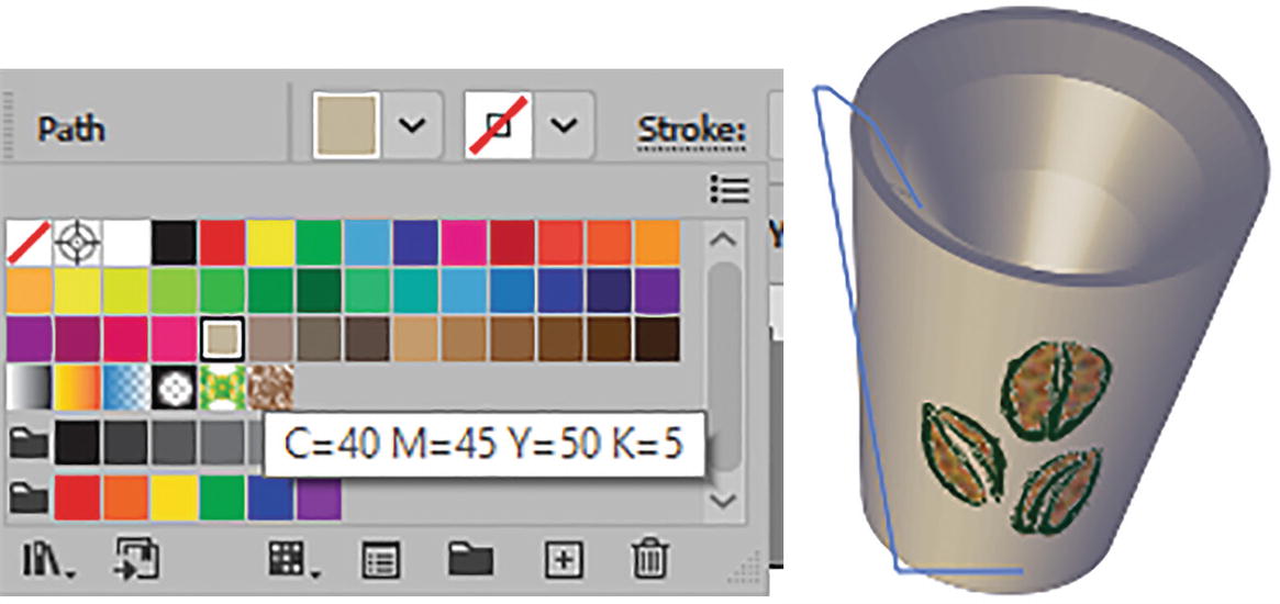
Use the Control panel to change the color of the object afterward

You can create many simple shapes with open paths
However, sometimes if there are a number of grouped open paths the shape can start to become complex, and this can cause a warning message in the dialog box. This can sometimes happen when paths cross, but I have not found that it causes any issues, as it is just a warning. Refer to Figure 13-108.

You can also create complex shapes with grouped open paths, but be aware of any alert messages in the Revolve (Classic) dialog box
Another warning you may encounter with Map Art symbols that have gradients is that those gradients will be rasterized.
Extrude & Bevel (Classic)

Effect menu settings for 3D and Materials ➤ 3D (Classic) ➤ Extrude & Bevel (Classic)

Select the closed path that you want to extrude
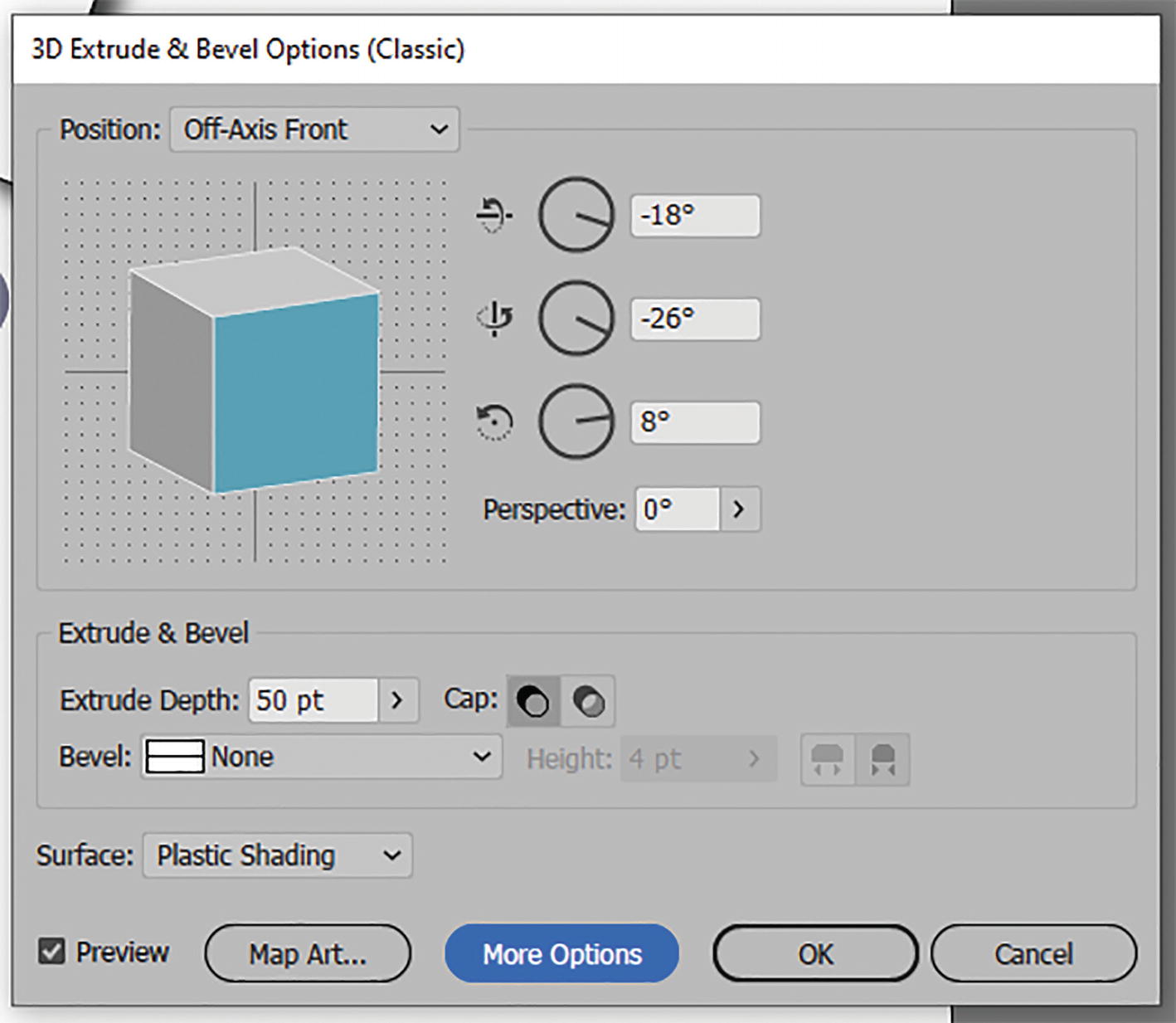
3D Extrude & Bevel Options (Classic) dialog box
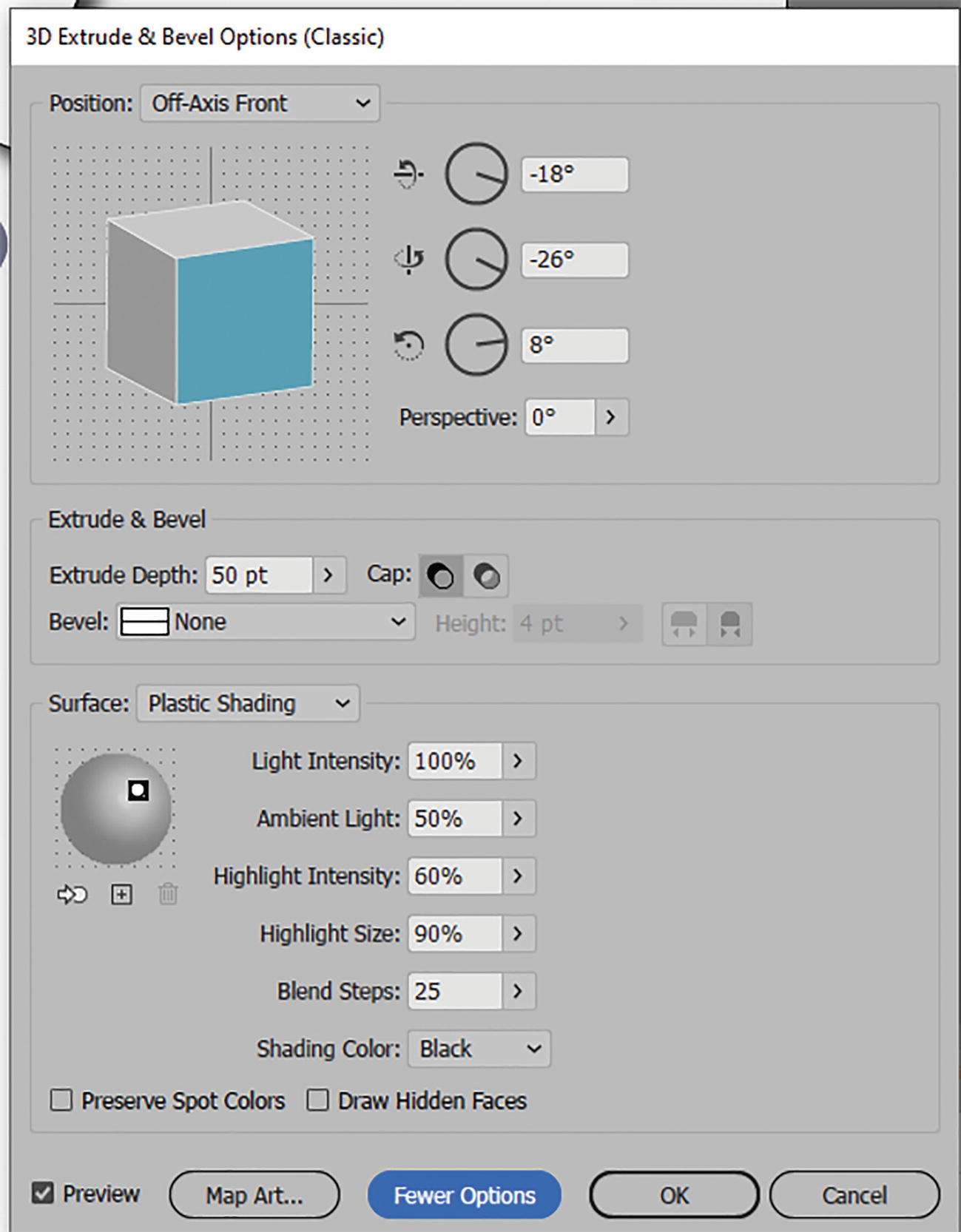
3D Extrude & Bevel Options (Classic) dialog box with More Options set

Extruded rectangle
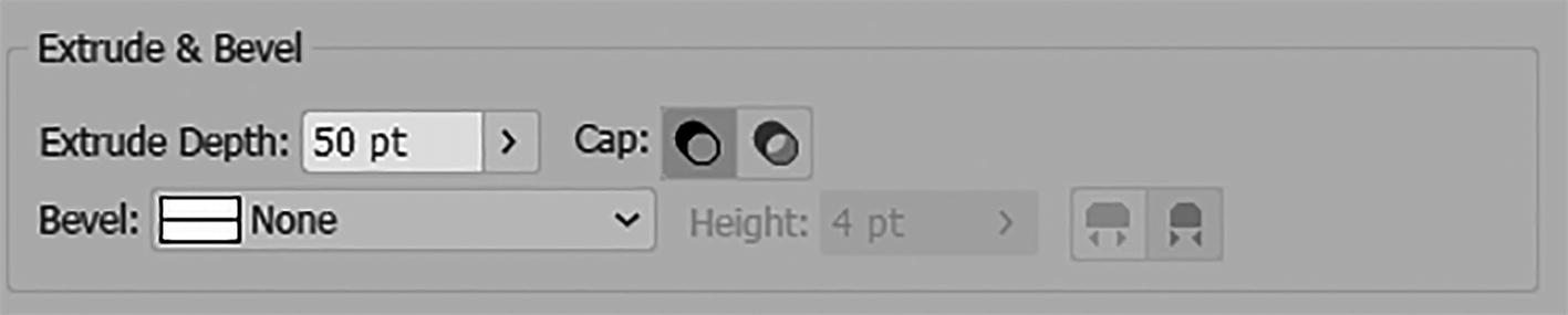
3D Extrude & Bevel Options (Classic) dialog box with Extrude & Bevel options

Extruded rectangle with an Extrude Depth set to 189 pt

Extruded rectangle with Perspective angle adjusted and then set back to 0°

3D Extrude & Bevel Options (Classic) dialog box with Cap settings on
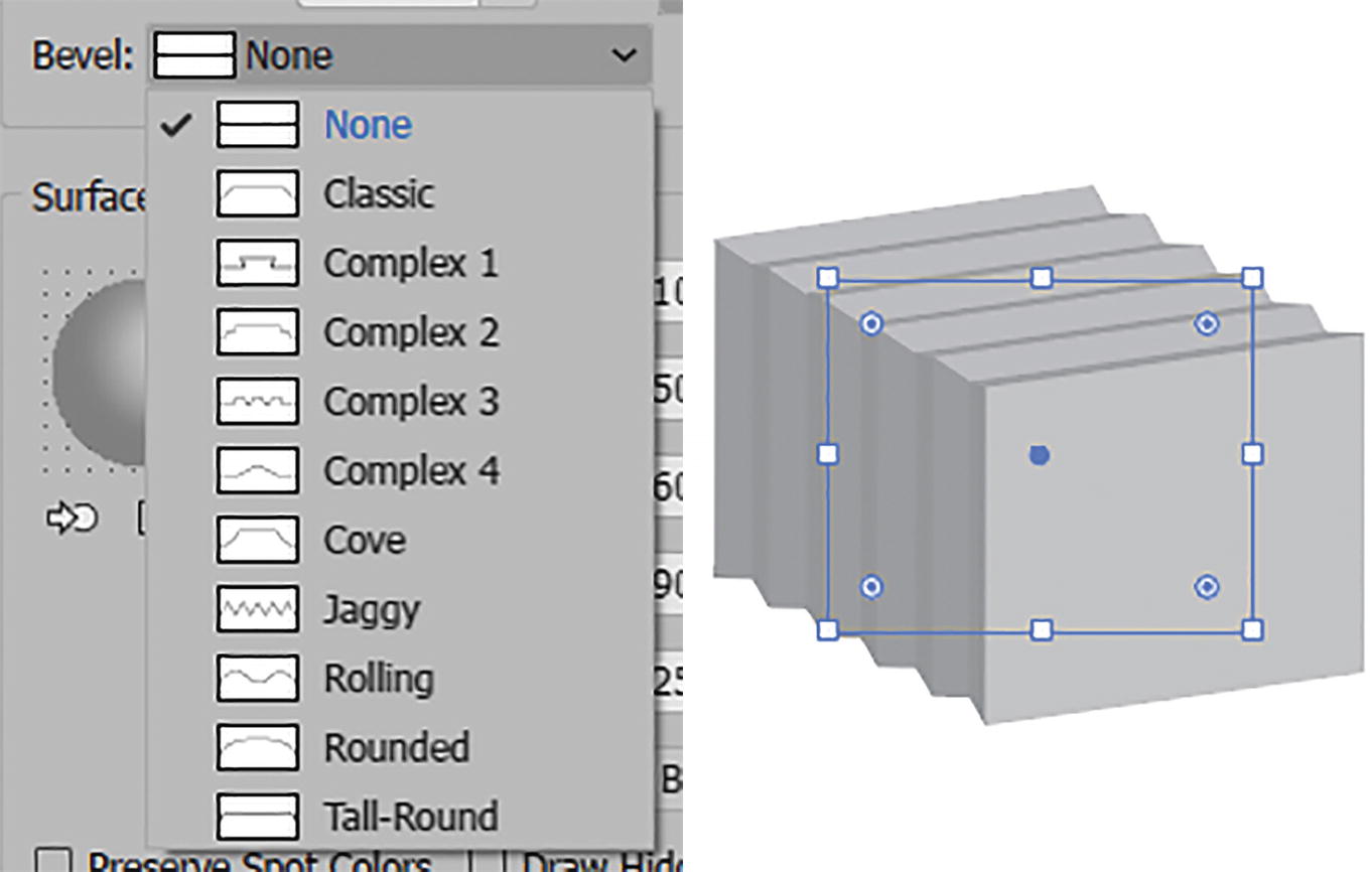
3D Extrude & Bevel Options (Classic) dialog box with Bevel list, and then set to Jaggy

3D Extrude & Bevel Options (Classic) dialog box with Height and bevel extent settings
At the bottom of the dialog box, you may get a warning when you use the bevel that self-intersection may have occurred. You can ignore this message. Refer to Figure 13-120.
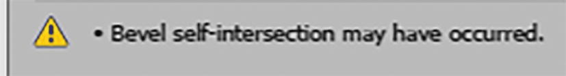
3D Extrude & Bevel Options (Classic) dialog box alert when a bevel is set

3D Extrude & Bevel Options (Classic) dialog box surface plastic shading options with a custom shading color, and how it appears in the preview
Map Art

3D Extrude & Bevel Options (Classic) dialog box Map Art button
Map Art dialog box with symbol applied to face, and how it appears in the preview

3D Extrude & Bevel Options (Classic) dialog box; click OK to exit
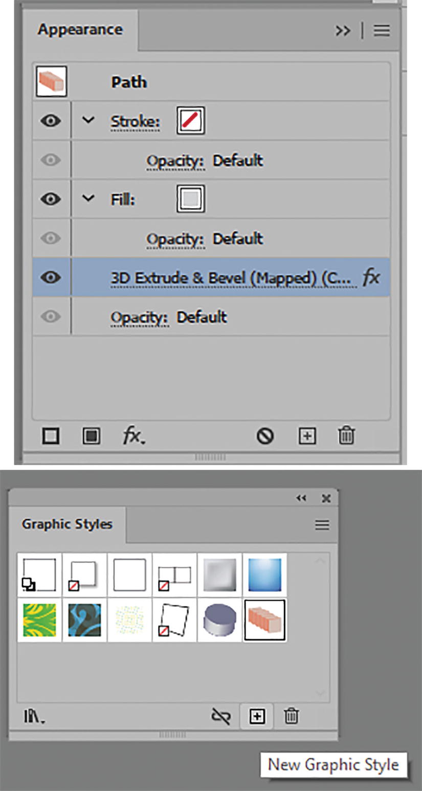
Appearance panel with effect, which can be added to the Graphic Styles panel

Changing the fill color of the extrusion afterward using the Control panel
Use the Selection tool if you want to scale or move the extrusion.
3D Extrude and Bevel (Classic) type example
This is a good alternative if you need to copy 3D text into Photoshop as a Smart Object layer.
Save your work and refer to my file 3D_Classic.ai if you want to look at these examples.
To view some more complex examples you can check out https://helpx.adobe.com/illustrator/using/creating-3d-objects.html.
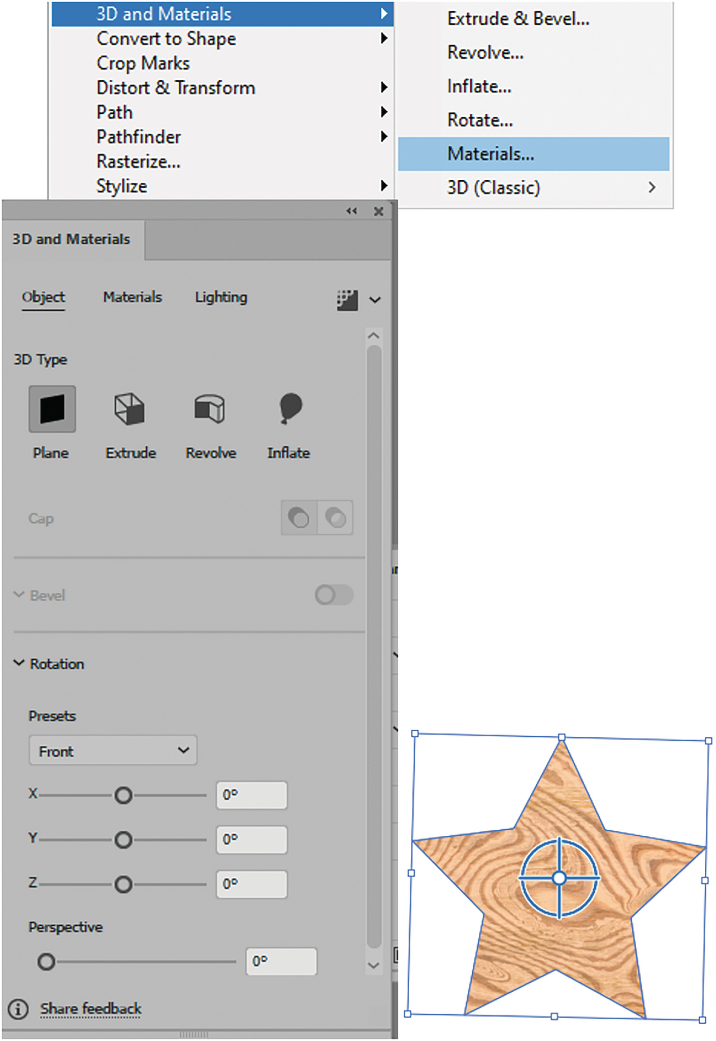
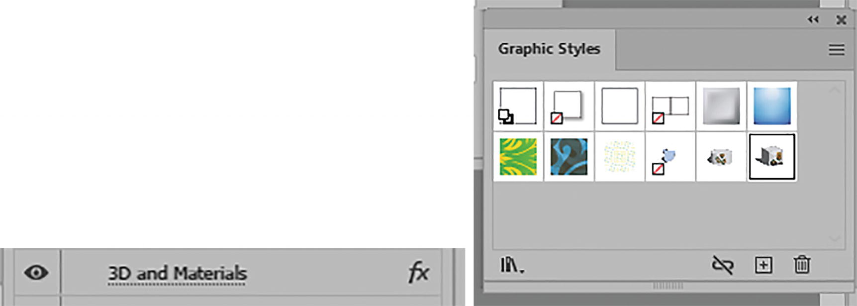
Effect ➤ 3D and Materials Panel

Effect ➤ 3D and Materials panel
Extrude & Bevel
Revolve
Inflate
Rotate
Materials
3D and Materials panel
Project: Coffee Cup Example
Open coffee_cup_3D.ai.
In this example, I will show you some of the same examples of a coffee cup, which this time I created using the Window ➤ 3D and Materials panel. Refer to Figure 13-129.
These 3D effects can only be applied as one instance to an object; however, you can use other non-3D effects in combination. Refer to Figure 13-130.

Alert message for applying more than one 3D and Materials effect
Rotate
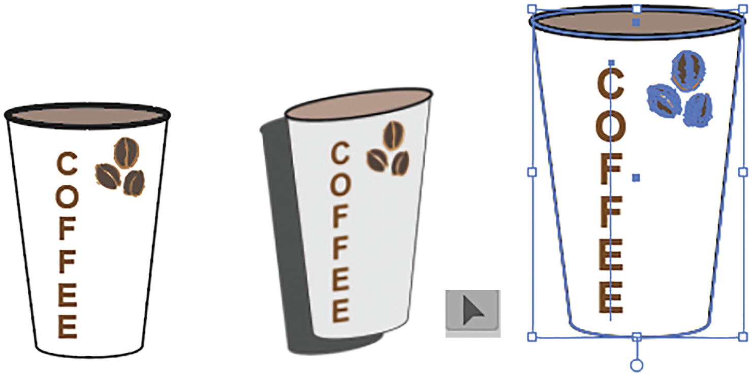
Select the object with the Selection tool to apply the 3D effect
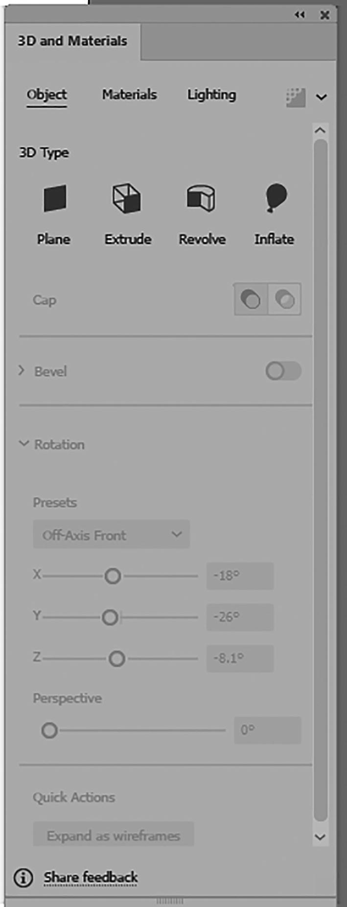
3D and Materials Object Tab
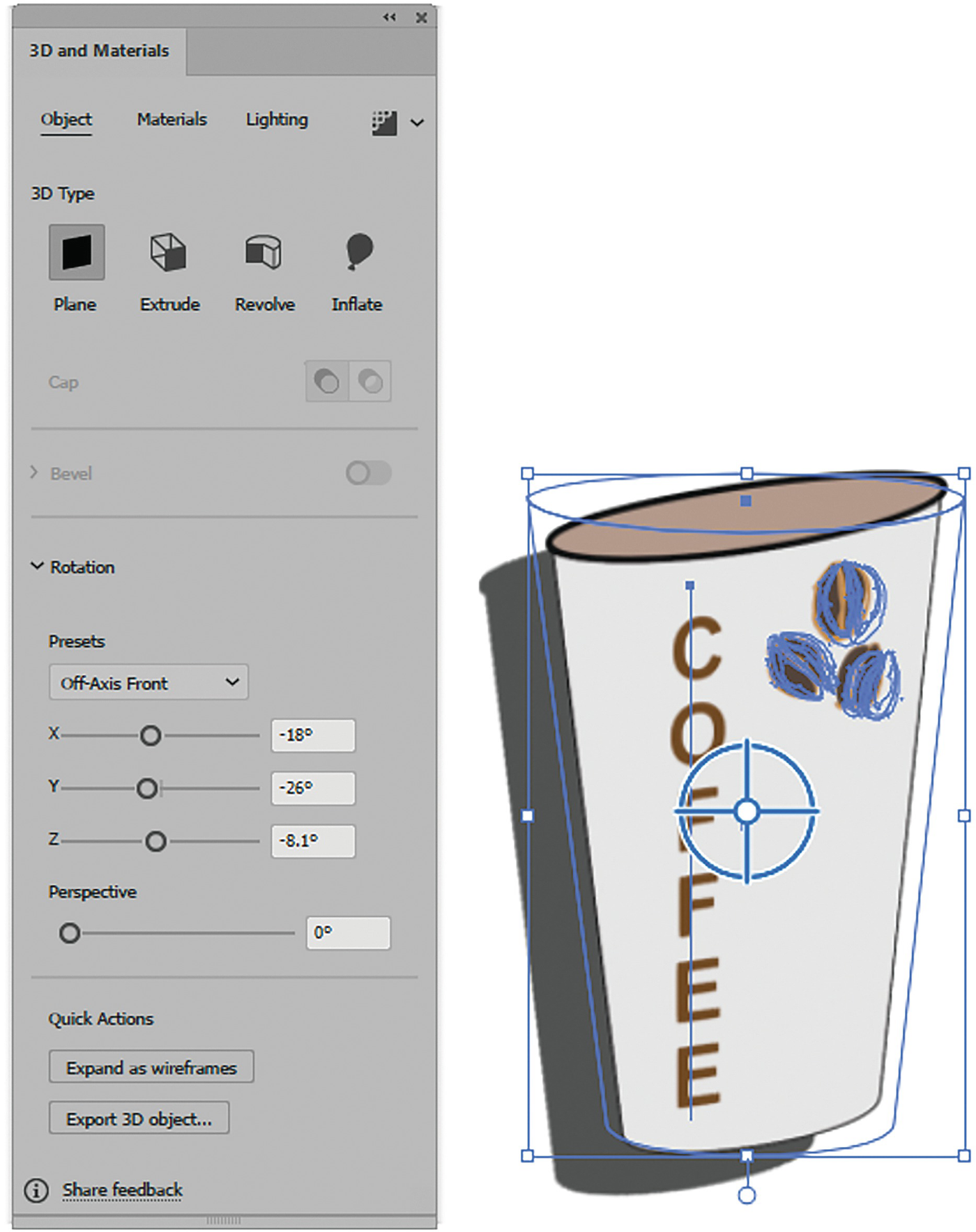
3D and Materials panel, Plane (Rotate) setting, and preview

3D and Materials panel Plane (Rotate) setting, presets, and preview

3D and Materials panel Plane (Rotate) setting and preview for Rotate around X

3D and Materials panel Plane (Rotate) setting and preview for Rotate around Y

3D and Materials panel Plane (Rotate) setting and preview for Rotate around Z
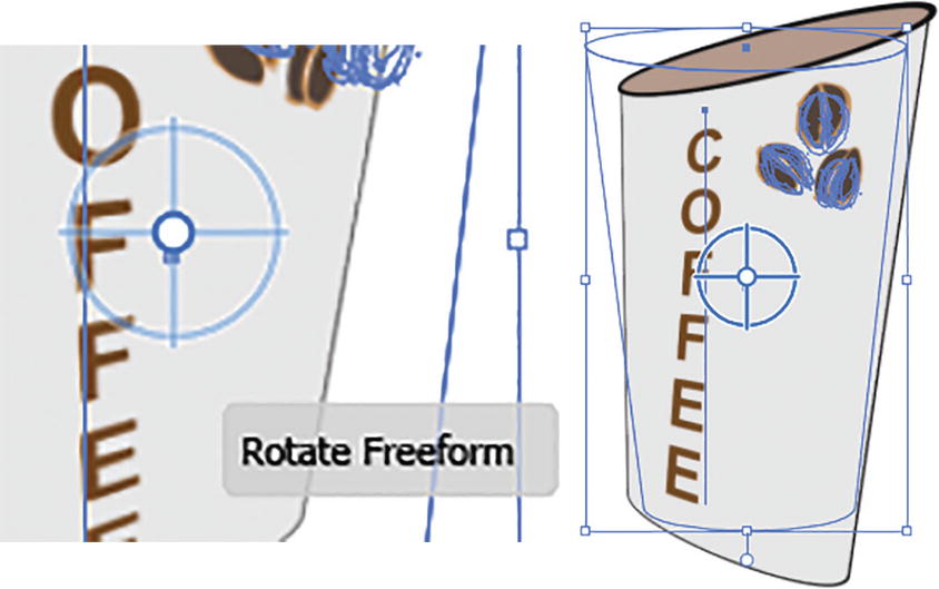
3D and Materials panel Plane (Rotate) setting and preview for Rotate Freeform
To undo any of the steps you can choose Edit ➤ Undo or Ctrl/CMD+Z, or use the History panel.
While in the Object tab for Plane, you will notice that the cap and bevel options are not available. You do, however, have the option to expand as a wireframe in the Quick Actions area. This creates a type of grouped-path outline of the object. Edit ➤ Undo that last step.

3D and Materials panel Plane (Rotate) setting, or set to another 3D type, or expand as a wireframe or export 3D object
Additionally, you can now use the Quick Actions to Export your 3D object to the Asset Export Panel. See the end of this 3D and Materials section for a link on this topic.
Besides setting the Object settings, you also have access to three other tabs: Materials, Lighting, and Render.
Materials Tab
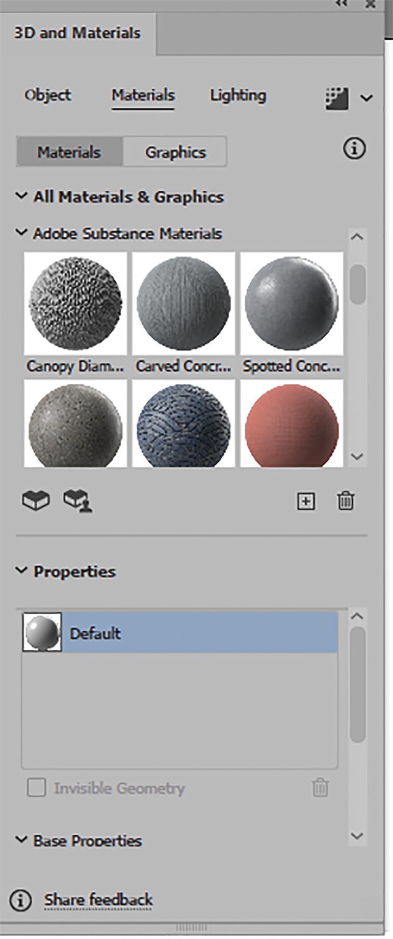
3D and Materials panel Plane (Rotate) Materials tab
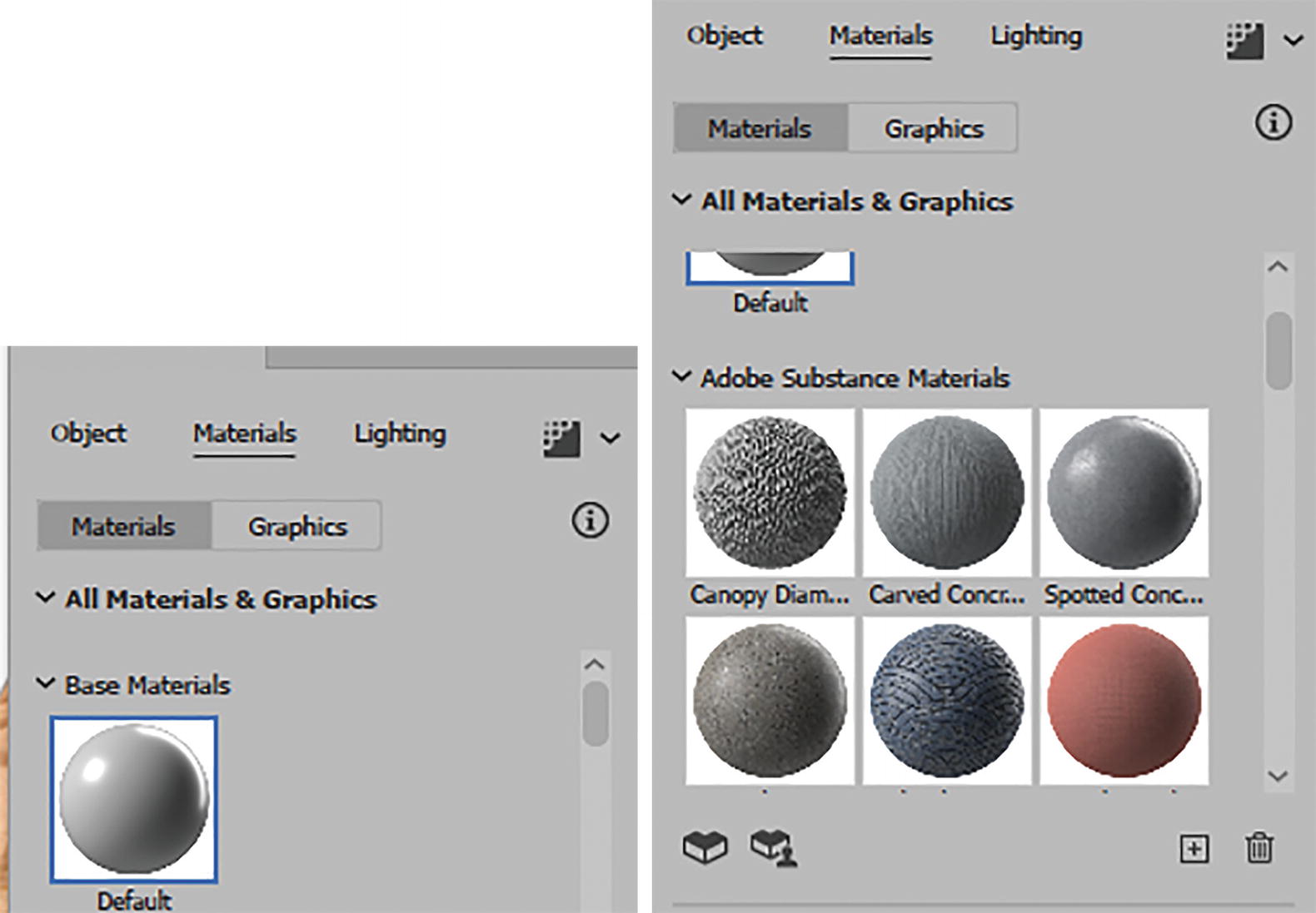
3D and Materials panel Plane (Rotate) Materials tab
If you need to expand this area to see more materials, then drag on lower edge of the panel to enlarge it. Refer to Figure 13-141.
3D and Materials panel, drag to lengthen the panel

3D and Materials panel Plane (Rotate) Materials tab, Add Materials and file format
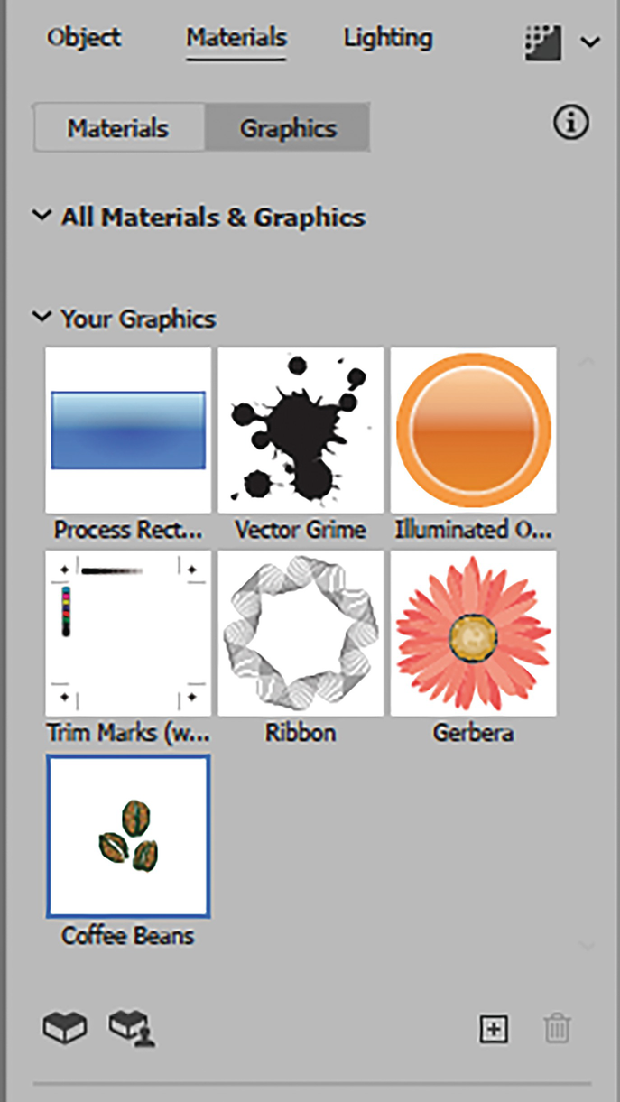
Add Single and Multiple Graphics Symbols
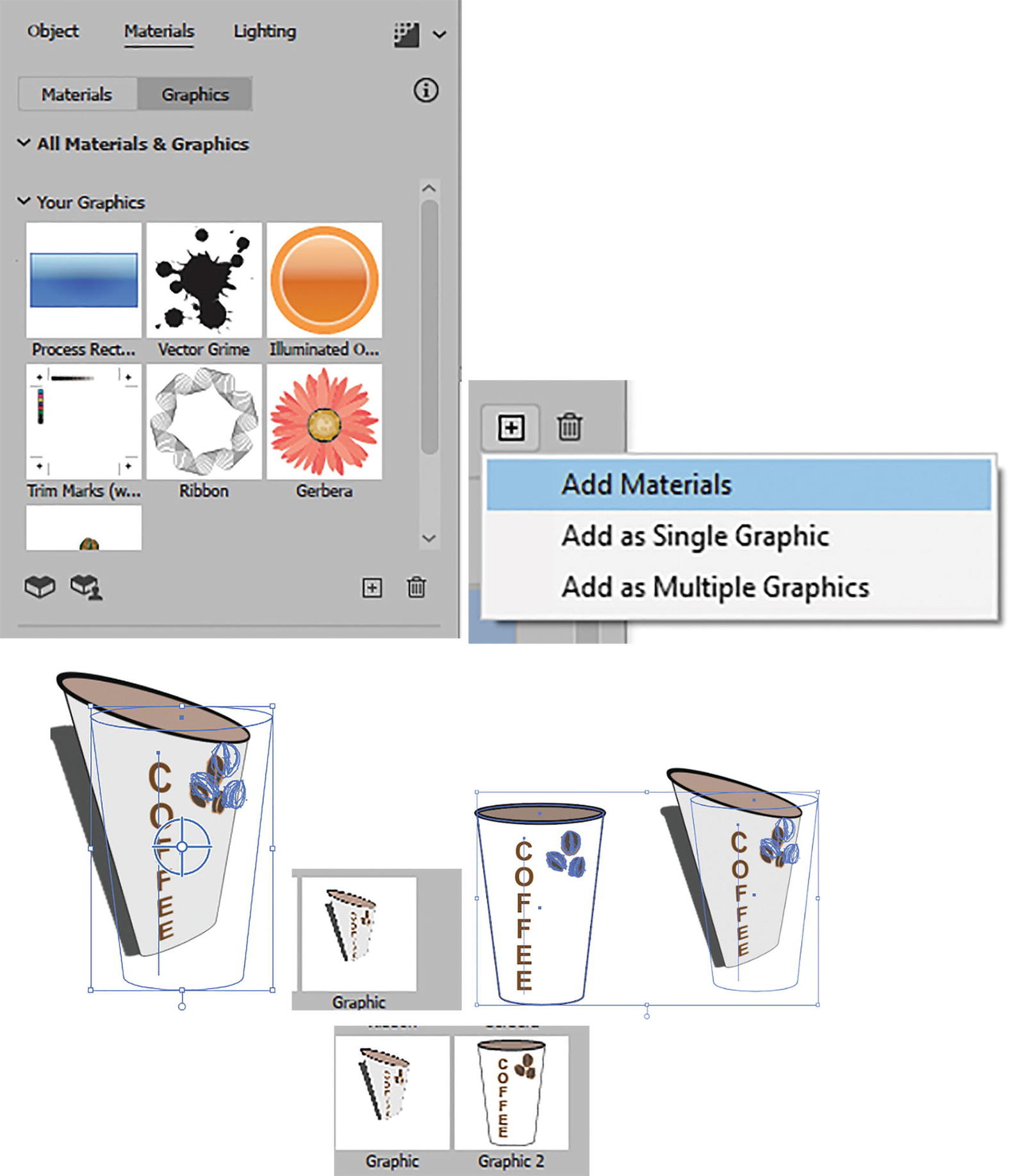
3D and Materials panel Plane (Rotate) Materials (Graphics) tab, adding symbols graphics, and preview of graphic on object; and add single and multiple graphics to the 3D and Materials panel and Symbols panel at the same time
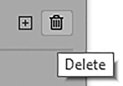
3D and Materials panel Plane (Rotate) Materials tab Delete Graphic button
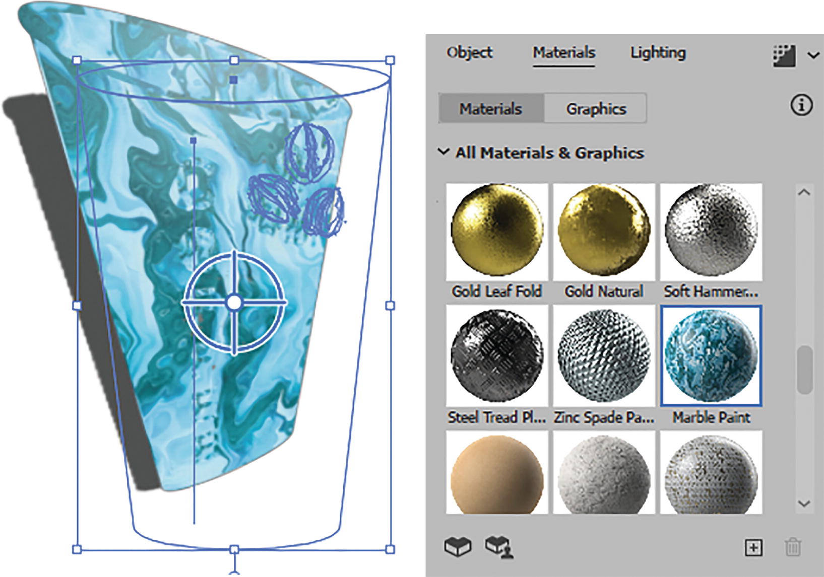
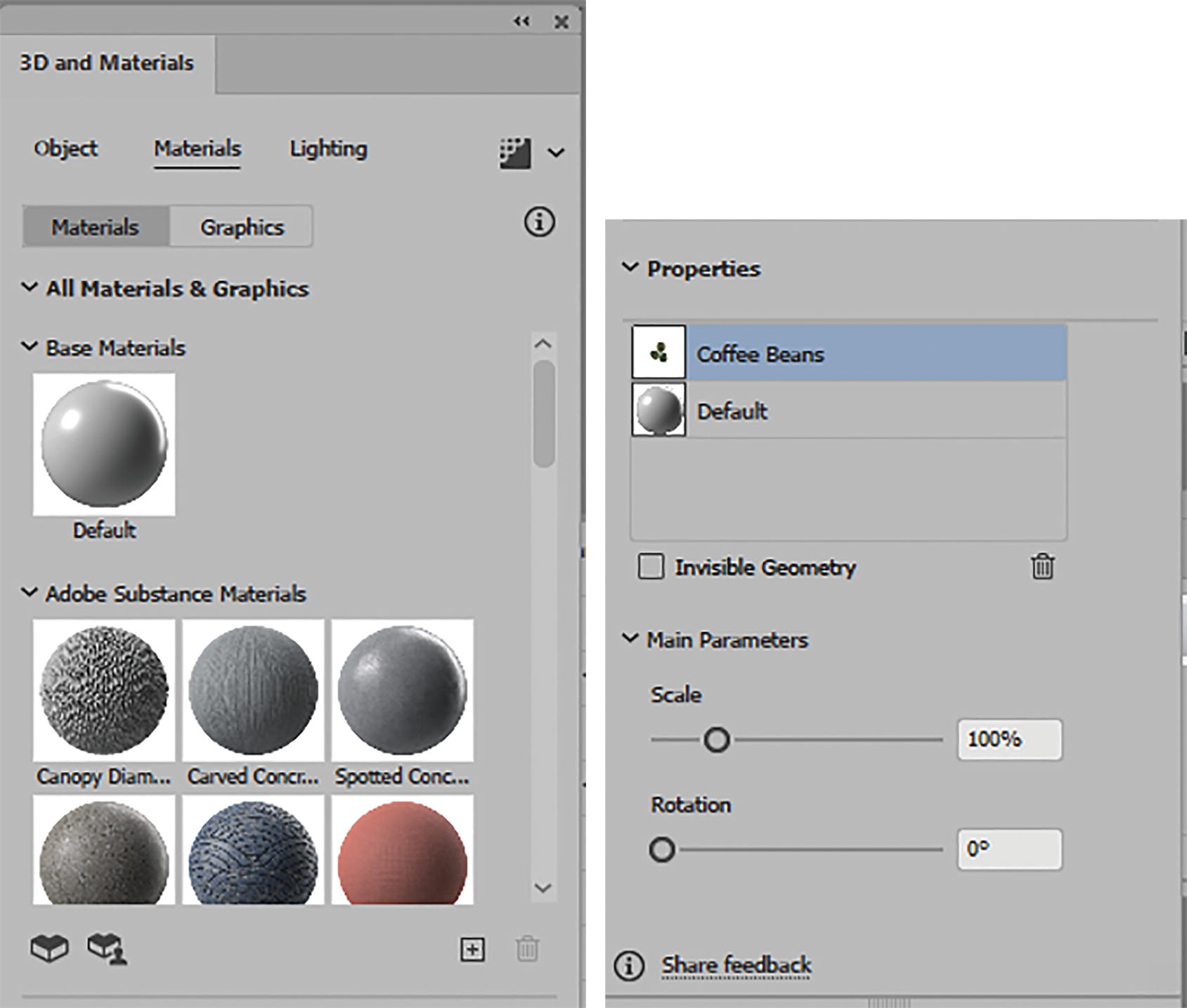
3D and Materials panel Plane (Rotate) Materials tab with a material selected

3D and Materials panel Plane (Rotate) Materials tab with material added to Properties section and additional settings viewed in Main Parameters section
Some main parameters are complex, and other materials may only have a few options, so you need to spend time and look at each one after you select your substance material.
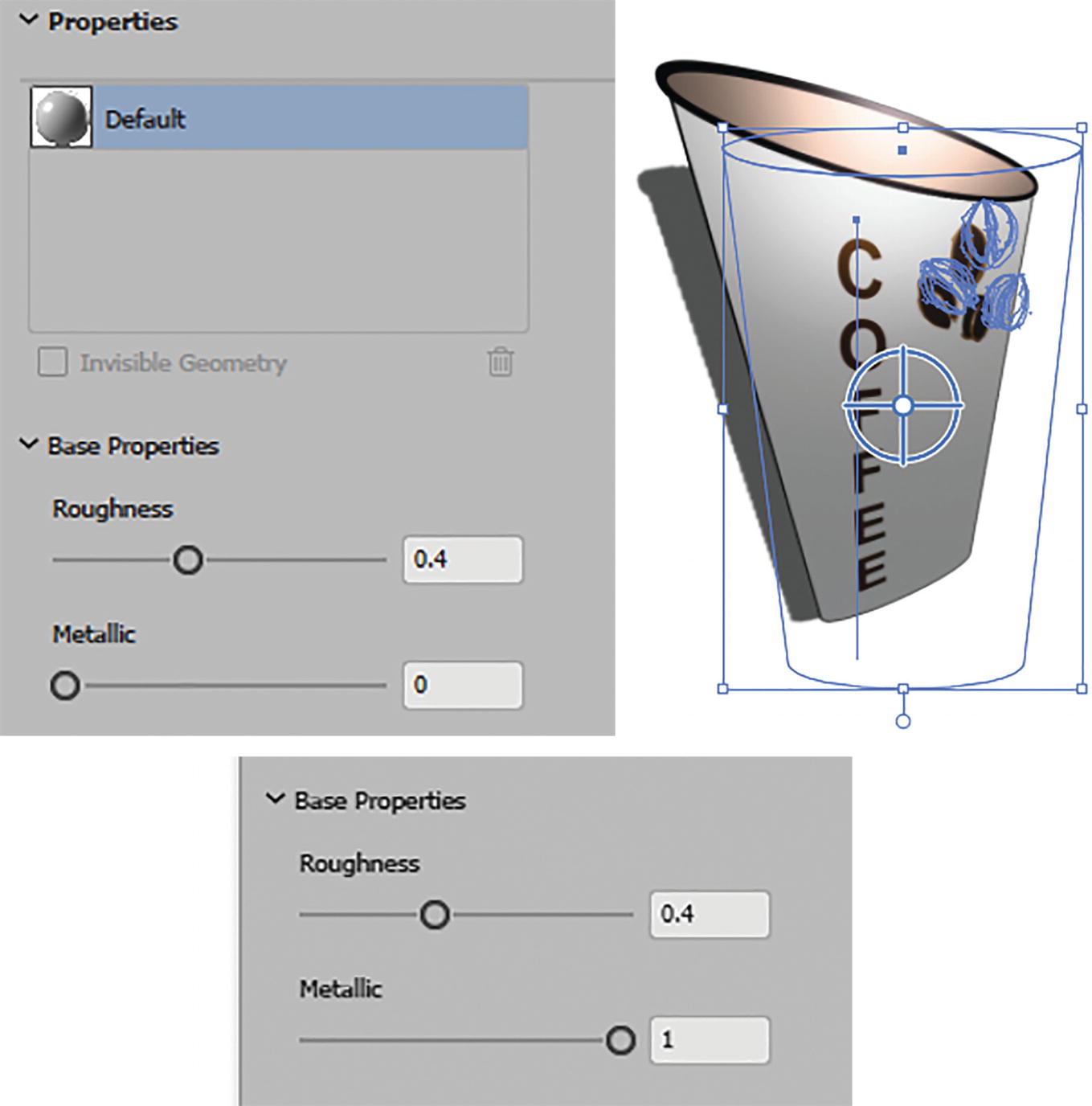
3D and Materials panel Plane (Rotate) Materials tab, Default material and base properties, and preview of object with a higher metallic setting
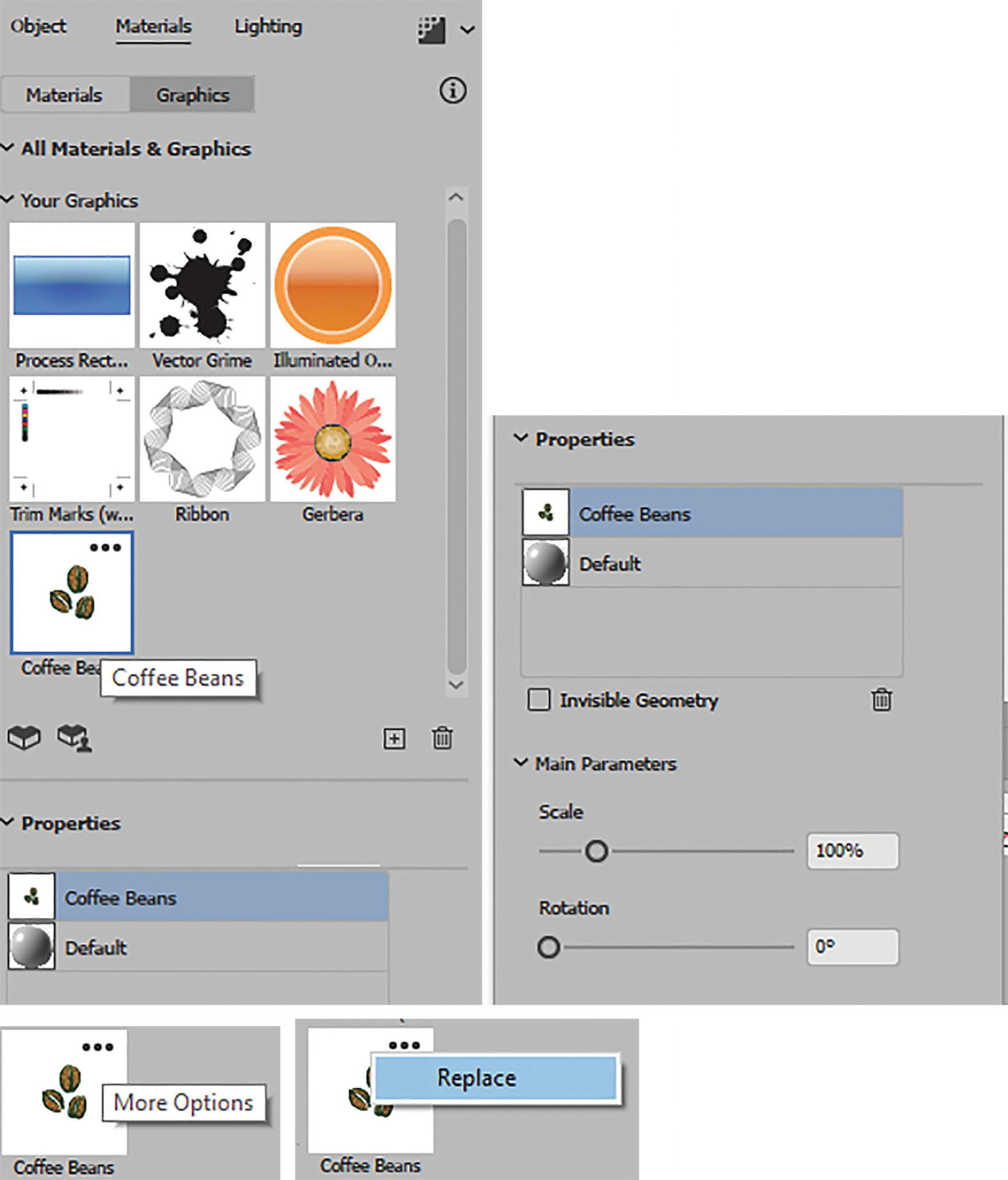
3D and Materials panel Plane (Rotate) Materials tab, Graphic Properties, and Main Parameters for selected graphic
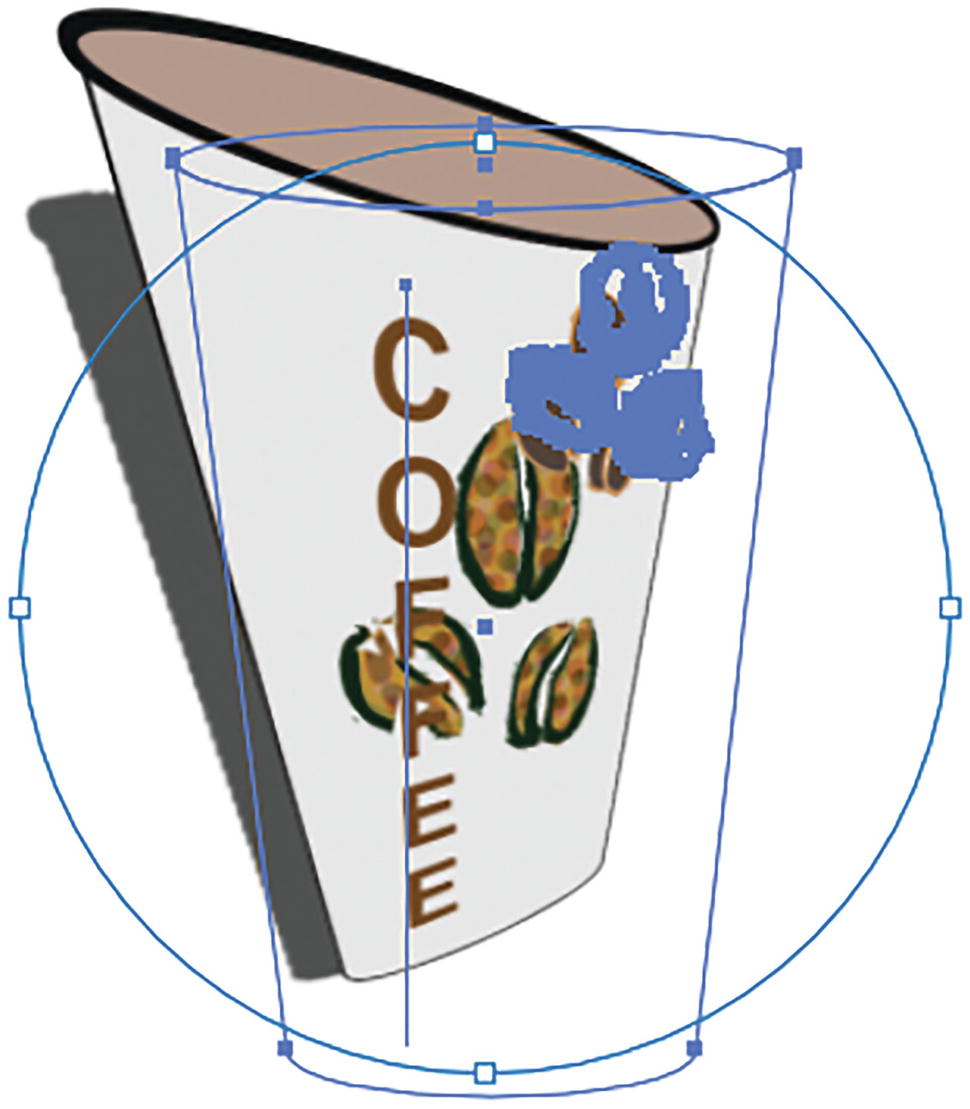
Move, scale, and rotate the selected graphic on the object

Remove graphic from Properties area
We will look at the Properties area again when we look at the other 3D settings, but for now you can select the graphic in the Properties section and remove it, and the symbol will be removed from the object. Use Edit ➤ Undo to undo that last step. Refer to Figure 13-150.
Lighting Tab
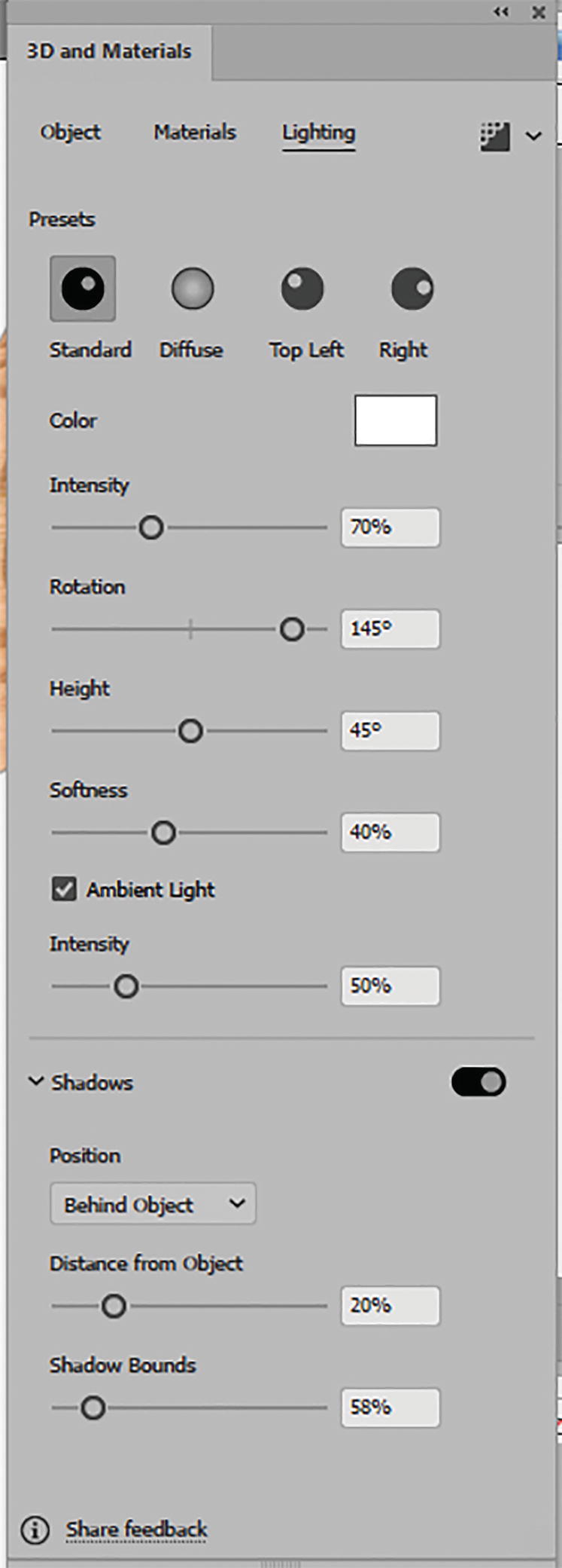
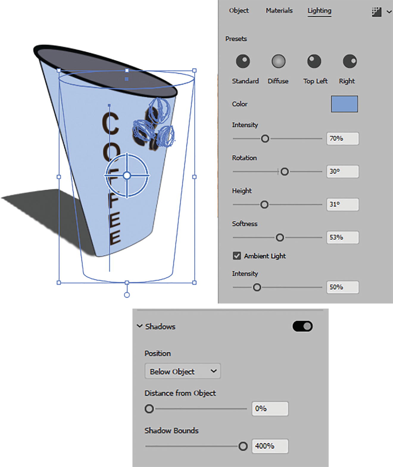
3D and Materials panel Plane (Rotate) Lighting tab

3D and Materials panel Plane (Rotate) Lighting tab, presets

3D and Materials panel Plane (Rotate) Lighting tab settings, set new color preset, and view the result
Other Lighting settings include the following:
Intensity (0%–200%): Brightness of light
Rotation (-180°,0°,180°): Rotates the focus of light around object
Height (0°–90°): Brings or moves light closer or farther away from object
Softness (0%–100%): Determines how the light spreads and creates a fuzzy effect that can override the Diffuse preset. This is more apparent after the object is rendered.
Ambient Light: Currently enabled and controls the global setting of the Intensity of the ambient light (0%–200%). Refer to Figure 13-153.
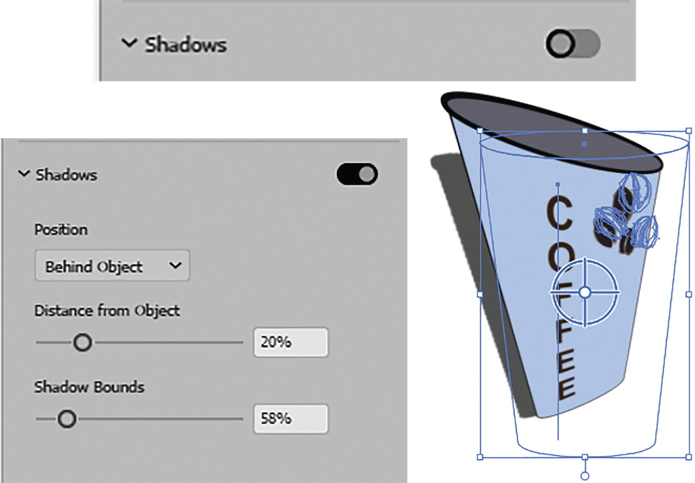
3D and Materials panel Plane (Rotate) Lighting tab, Shadows settings
This kind of shadow is a new feature, and you do not have to use a separate drop-shadow effect to create this shadow.
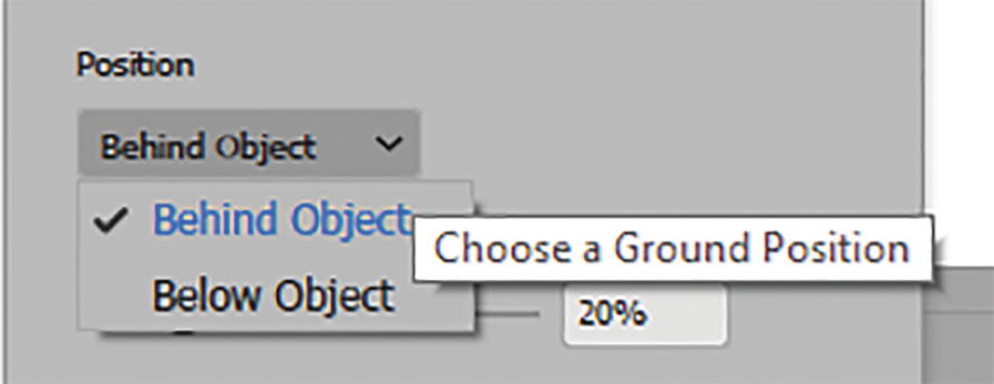
3D and Materials panel Plane (Rotate) Lighting tab, shadow set to ground position
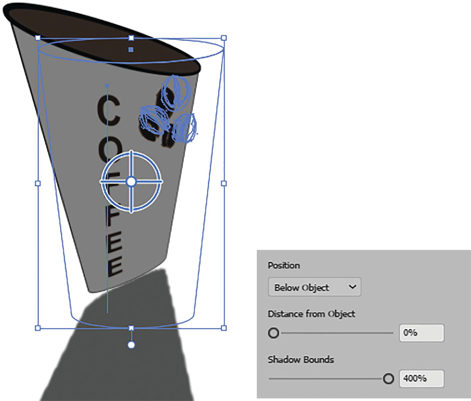
3D and Materials panel Plane (Rotate) Lighting tab, shadow options to set Distance from Object and Shadow Bounds
3D and Materials panel Plane (Rotate) Lighting tab settings and preview
It does not currently appear at this time that you can set more than one light source unless the Material Substance itself has a light source within its technical parameters. You can check in the Materials tab if it is present.
The Render Tab
If you choose later to render a real-time preview, you can use this tab to choose Ray Tracing options. With the Ray Tracing toggle active, you can set the quality to Low, Medium, or High, and choose Raster settings. See Chapter 11 about the Document Raster Effects Settings dialog box, found in the Effects menu.
Reduce Noise: Enabled to reduce the grainy appearance that may come from rendering

3D and Materials panel Plane (Rotate) Render tab
The setting Remember and apply to all applies these render settings to all existing and future 3D and Materials effects.
If you want to render a graphic, then click the Render button or the square icon. It will take few seconds to process depending on the Quality setting that was used. It will then be a grouped object or path that has the setting applied. You can use Edit ➤ Undo if you need to undo that step and return it to its original state.
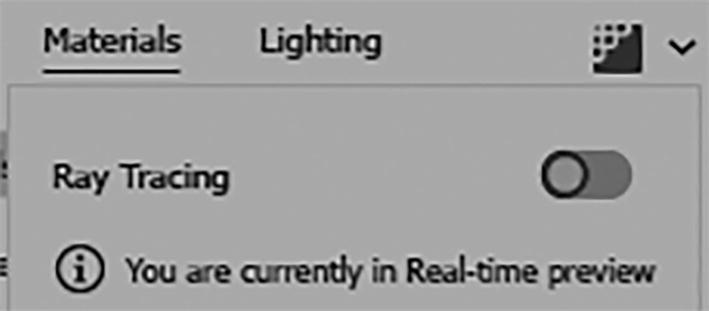
3D and Materials panel Plane (Rotate) Render tab, Ray Tracing toggle off
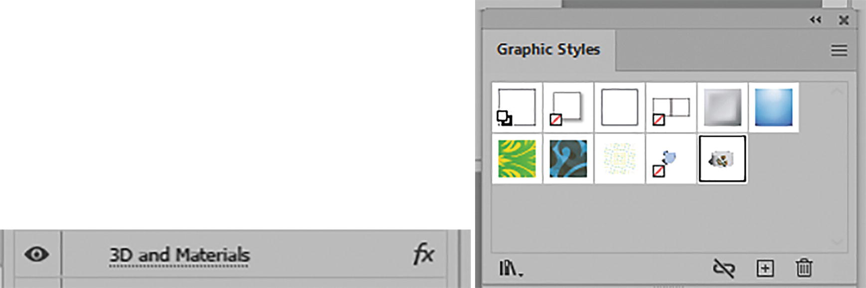
The effect will appear in the Appearance panel, and this effect, like the others, can be added to the Graphic Styles panel. Refer to Figure 13-160.
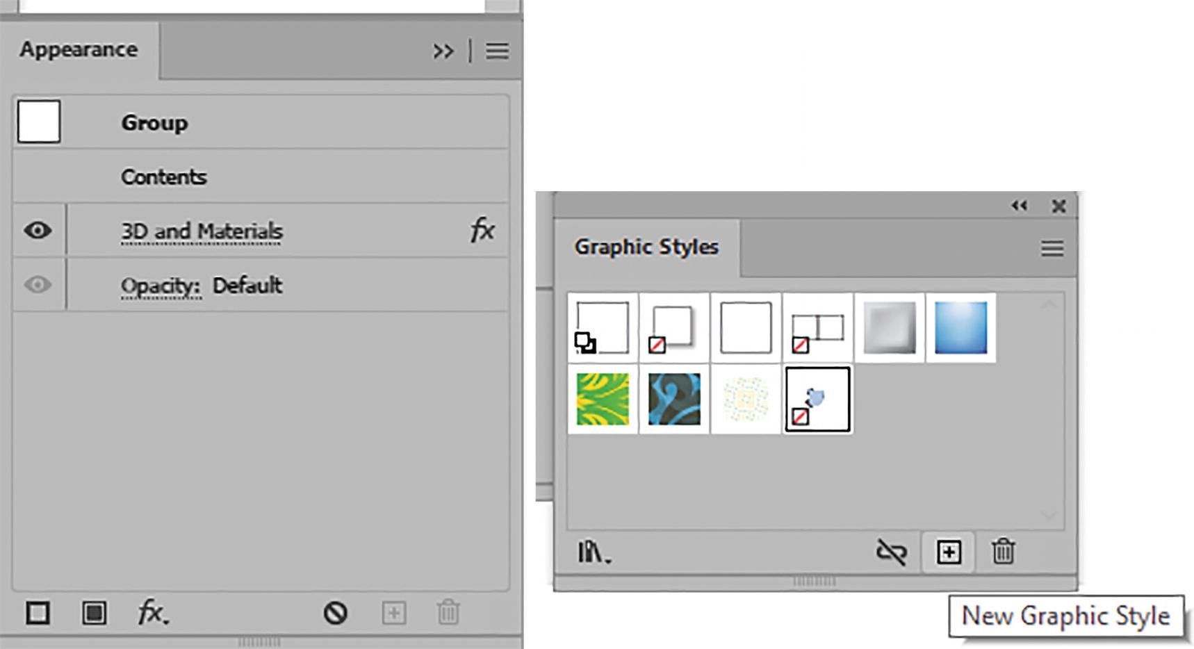
Appearance panel with 3D and Materials effect; effects added to Graphic Styles panel
Materials
3D and Materials panel; Plane (Material) object found in the 3D and Materials menu
However, afterwards as with the earlier mentioned Rotate effect, you can then set the Rotation presets for X, Y, Z, as well as the Perspective Angle, using the panel. As with the Rotation options, you can also utilize the other tabs that contain Materials, Graphics, and Lighting and Shadow to alter the graphic as well as render it. Otherwise, there are no real differences between this setting and Rotate for a Plane. Refer to Figure 13-161.
Revolve

Effect ➤ 3D and Materials ➤ Revolve
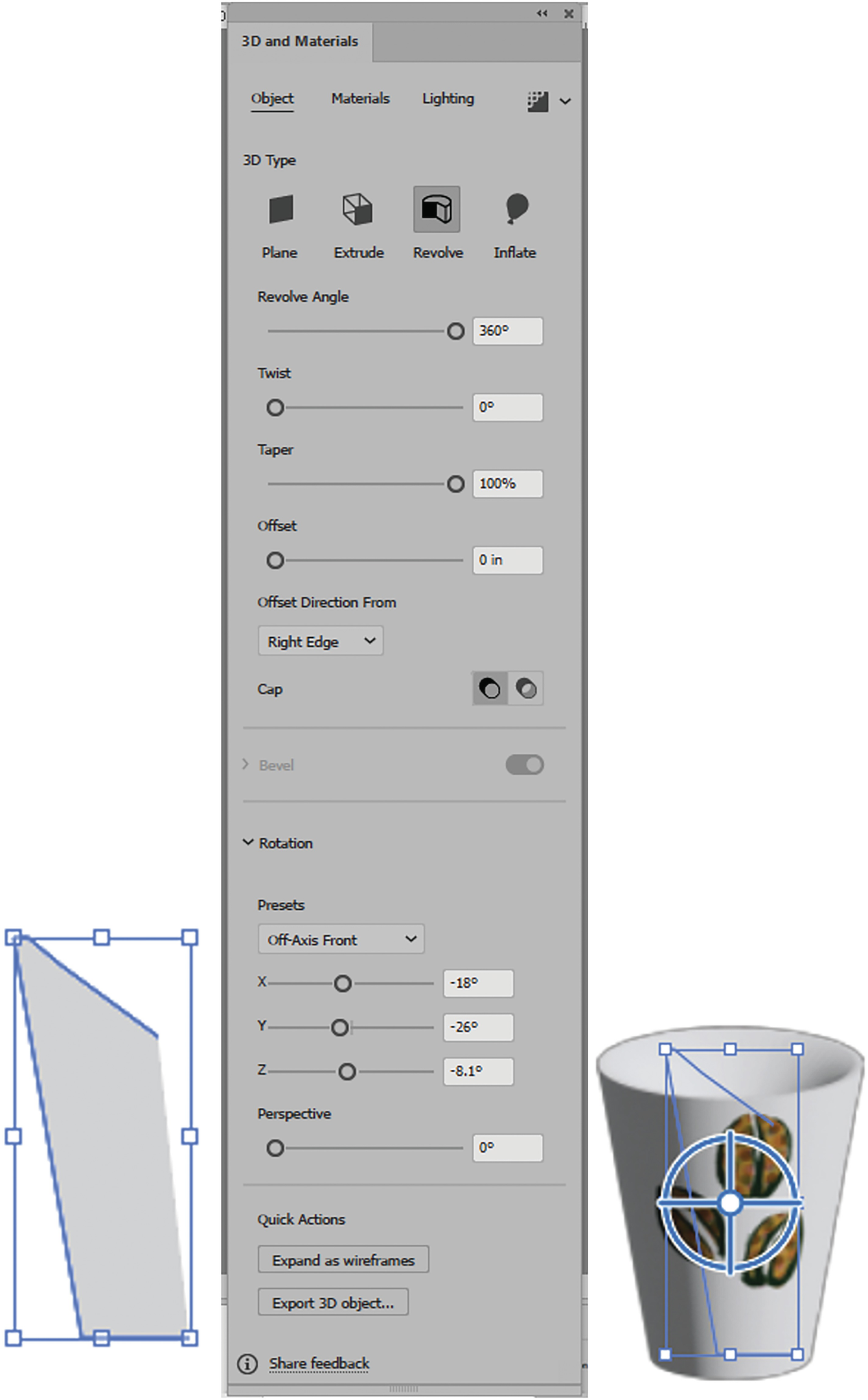
Open path, 3D and Materials panel Object ➤ Revolve tab, and preview of Revolve
In the panel you can see that many of the panel options are the same, so refer to the Rotate section for more details. I will just point out the main differences.
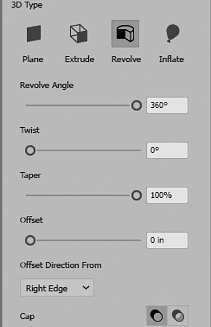
3D and Materials panel Object ➤ Revolve tab and Revolve settings

3D and Materials panel Object ➤ Revolve tab with different Revolve Angle values

3D and Materials panel Object ➤ Revolve example with different Offset, Twist and Taper settings

3D and Materials panel Object ➤ Revolve tab with Offset Direction From settings of Left Edge and Right Edge and a preview
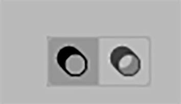
3D and Materials panel Object ➤ Revolve tab with Cap setting on
For Revolve, Bevel is not an available option. We will be looking at that in the next section. Refer to Figure 13-169.
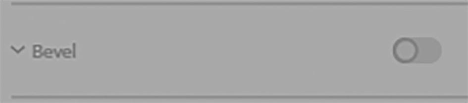
3D and Materials panel Object ➤ Revolve tab with Bevel unavailable

3D and Materials panel Object ➤ Revolve tab with preset settings for X, Y, and Z, and Perspective with its current setting
Materials Tab
3D and Materials panel Revolve ➤ Materials tab with Properties settings and a graphic symbol Materials button in this tab is currently selected
3D and Materials panel Revolve ➤ Materials tab with graphic symbol options in the Materials tab with the Graphics button currently selected

3D and Materials panel Revolve Materials tab, move graphic over cup
Lighting Tab

3D and Materials panel Revolve ➤ Lighting tab with Shadows settings

3D and Materials panel Revolve ➤ Render tab
Like rotate, this effect can be viewed and edited in the Appearance panel and added to the Graphic Styles panel. Refer to Figure 13-176.
Appearance panel with 3D effect that can be stored in Graphic Styles panel
Extrude & Bevel

Effect ➤ 3D and Materials ➤ Extrude & Bevel
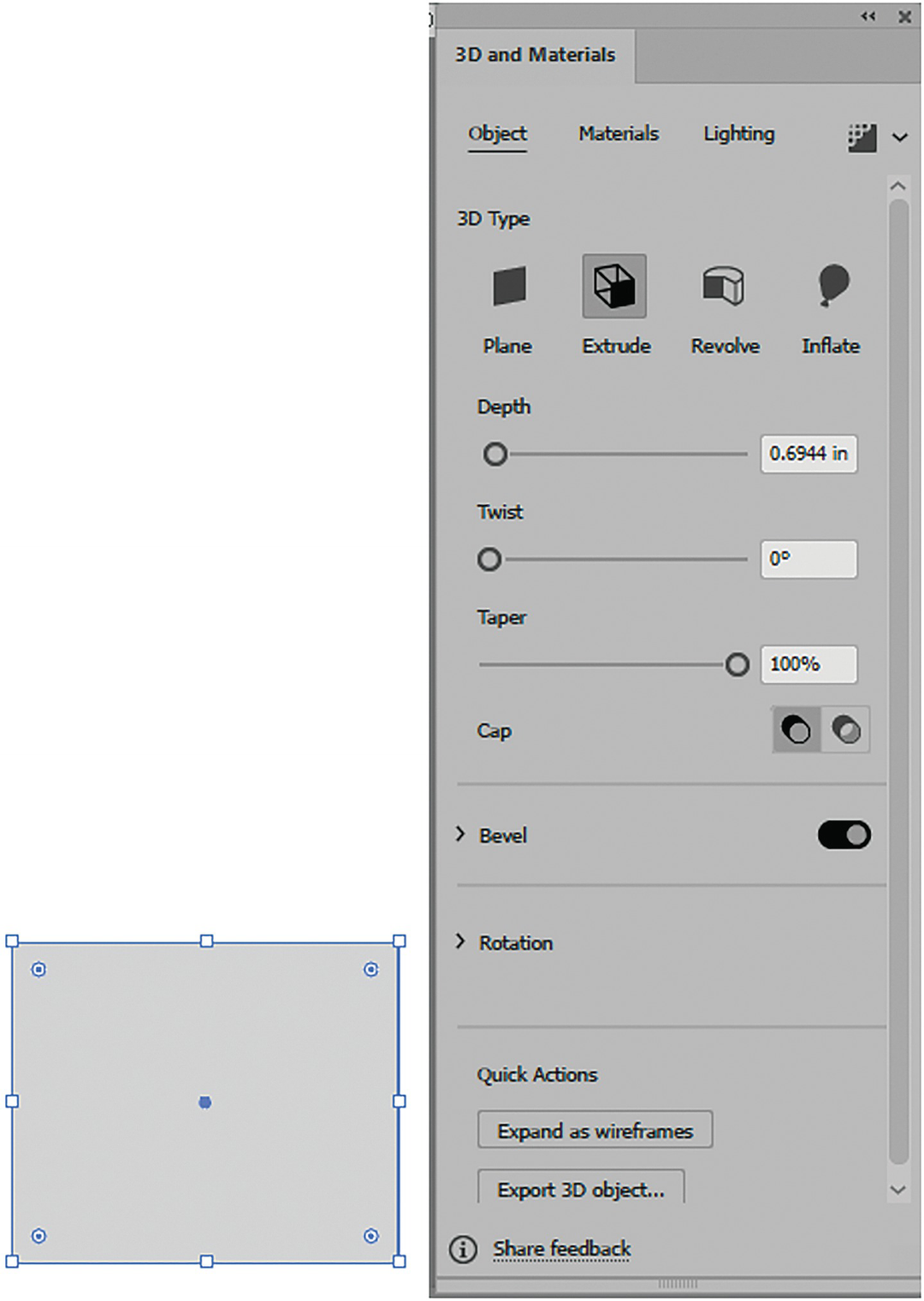
Selected rectangle with 3D and Materials panel’s Object tab (Extrude)
Rectangle with extrusion applied and then a twist and taper added

3D and Materials panel Object tab (Extrude) with Cap on and Cap off
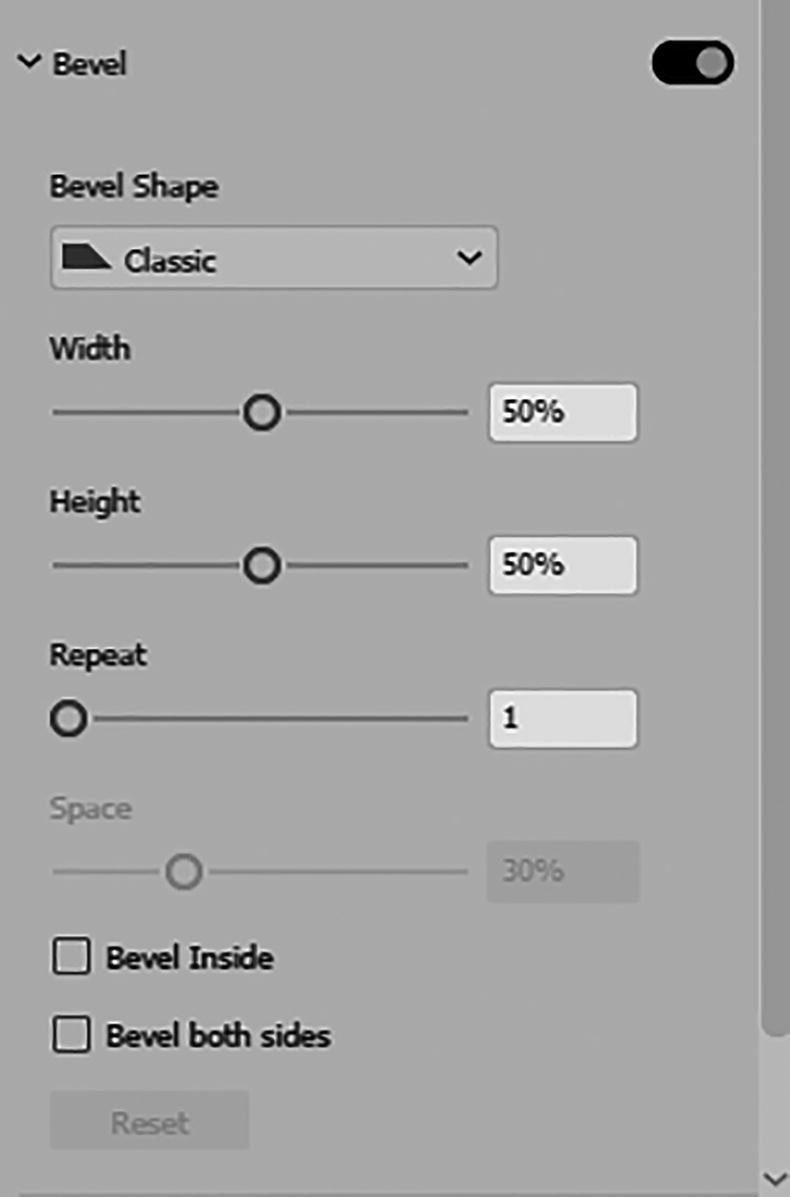
3D and Materials panel Object tab (Extrude) with Bevel settings
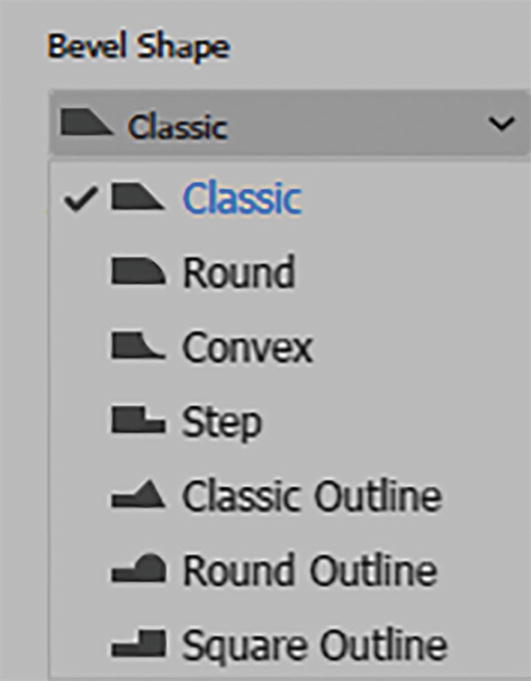
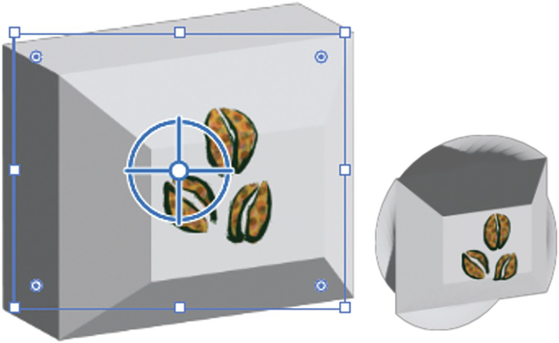
3D and Materials panel Object tab (Extrude) with Bevel Shape options
In this example, the option has been applied to one end of the object’s depth. You can then make further adjustments to the bevel.

3D and Materials panel Object tab (Extrude) with Bevel Width preview

3D and Materials panel Object tab (Extrude) with Bevel Height preview

3D and Materials panel Object tab (Extrude) with Bevel Repeat preview

3D and Materials panel Object tab (Extrude) with bevel Space and Repeat options

3D and Materials panel Object tab (Extrude) with Bevel Inside options
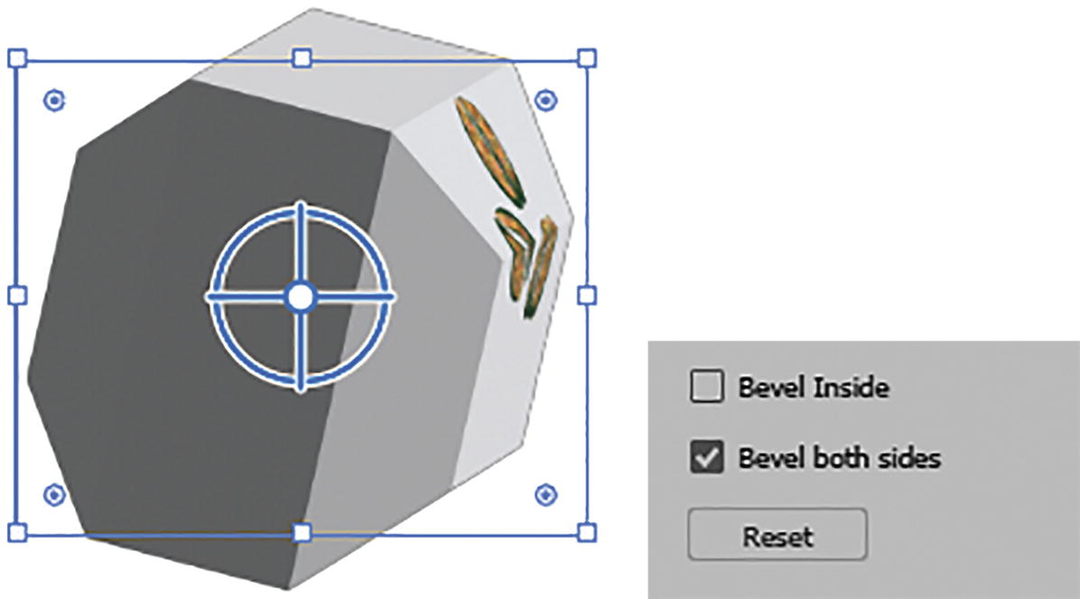
3D and Materials panel Object tab (Extrude) with Bevel both sides options
The next setting is Bevel both sides. It ensures that when you rotate the object, you can see the bevel on both sides. This is good, as one side might end up looking flat. Refer to Figure 13-118.
You can click the Reset button if you need to set the bevel setting back to the original state.
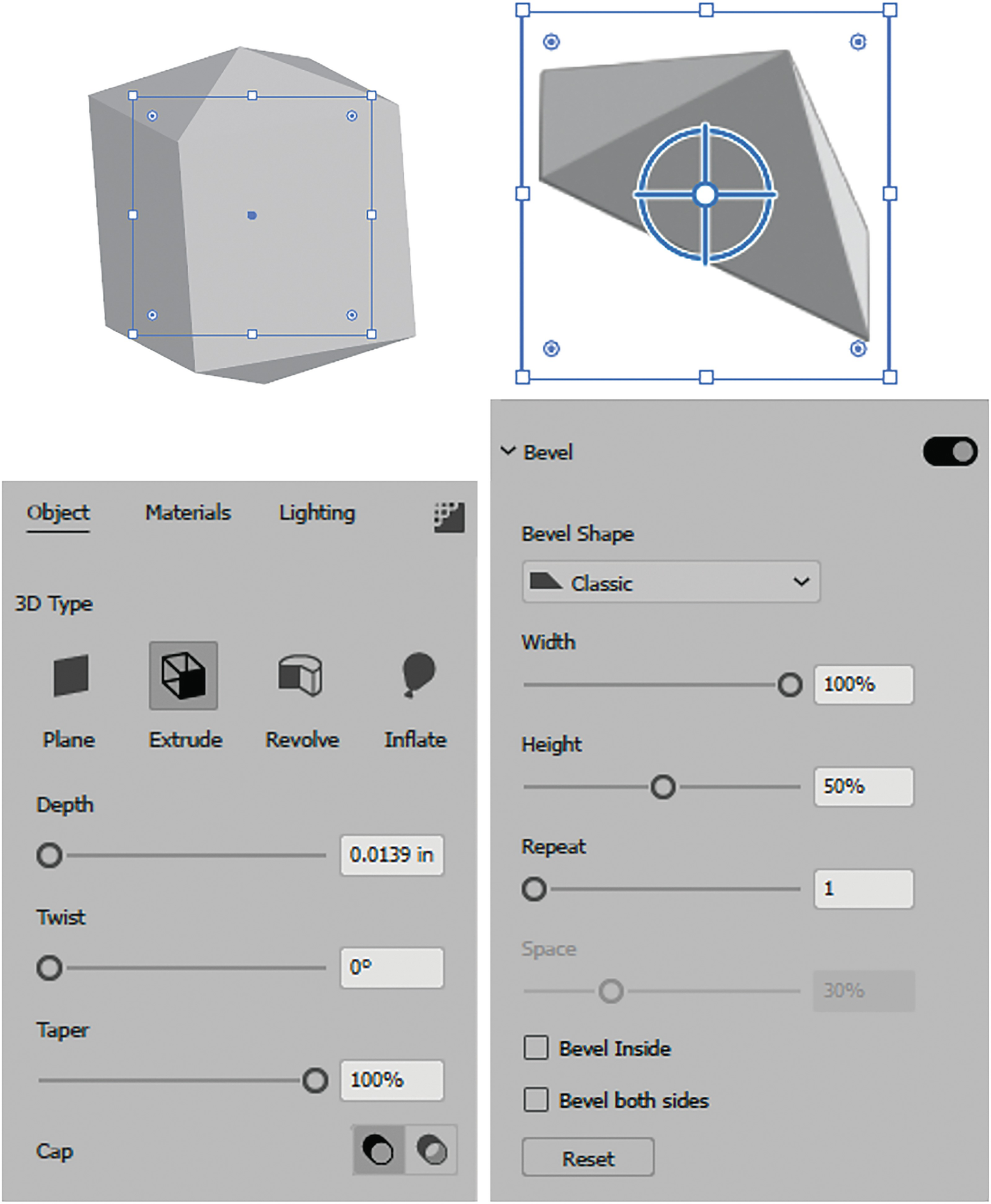
3D and Materials panel Object tab (Extrude) with improved bevel options compared to Extrude and Bevel (Classic)
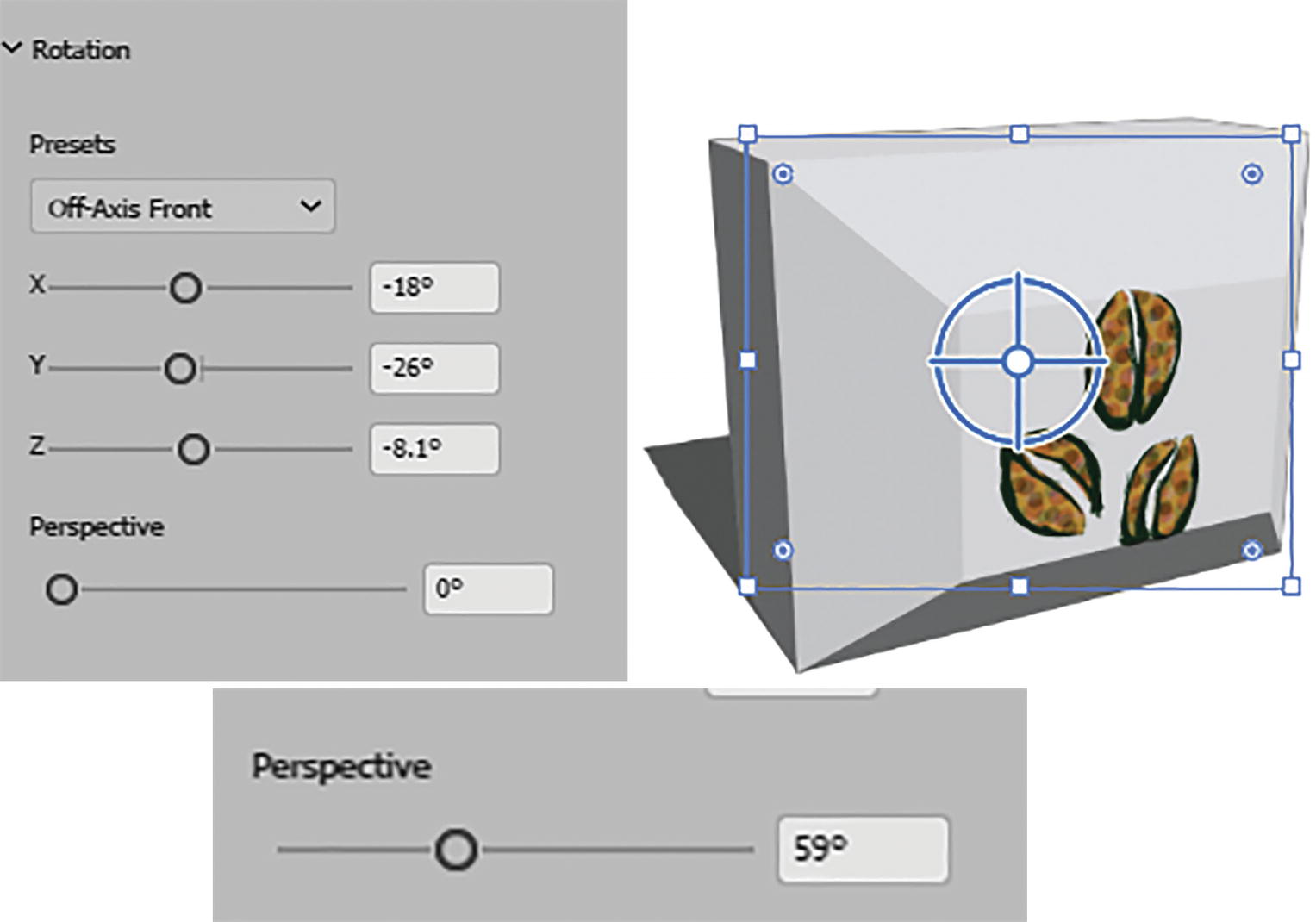
3D and Materials panel Object tab (Extrude), Rotate and Preset options, and Perspective settings
Materials Tab
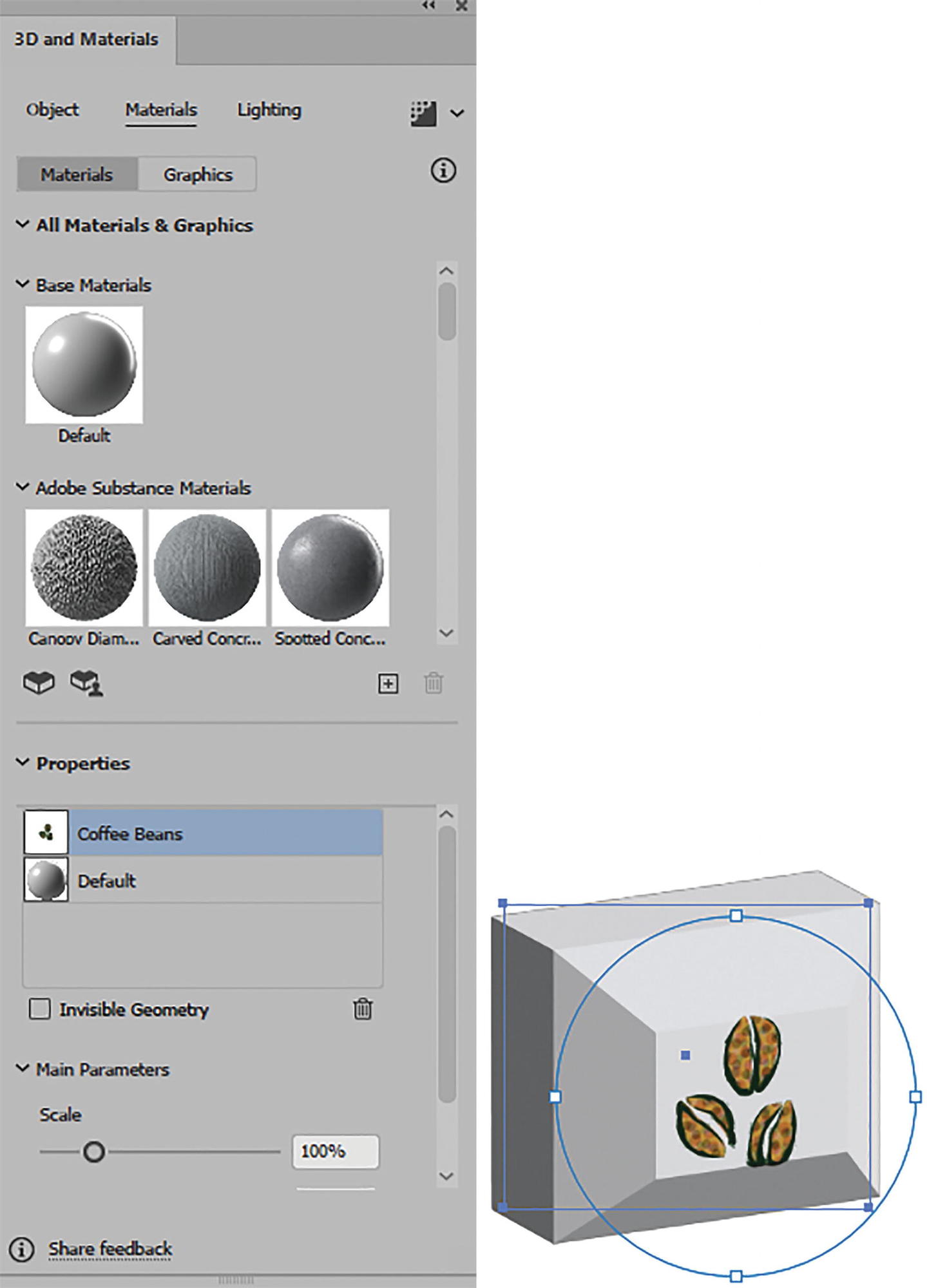
3D and Materials panel Materials tab for Extrude example, and graphics on object
Lighting Tab

3D and Materials panel Lighting tab (Extrude) with Shadows settings applied
3D and Materials panel for Render tab (Extrude)
Like Rotate, this effect can be viewed and edited in the Appearance panel and added to the Graphic Styles panel. Refer to Figure 13-194.
3D effect applied in Appearance panel and added to Graphic Styles panel

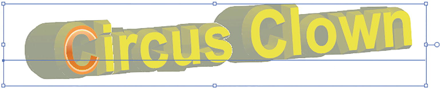
Text with 3D Extrude and Bevel effect
Inflate
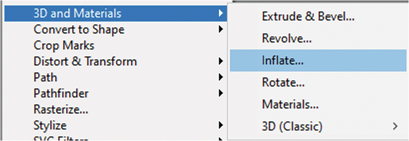
Effect ➤ 3D and Materials ➤ Inflate
In this case, select a closed path with the Selection tool; it could be a shape or even some type. Go to Effects ➤ 3D and Materials ➤ Inflate and look at the 3D and Materials panel.

Selected object with Selection tool, 3D and Materials panel Object tab (Inflate), with inflated 3D object
The 3D Type is now set to the Inflate setting, and the shape that is created is very much like a balloon. Refer to Figure 13-197.
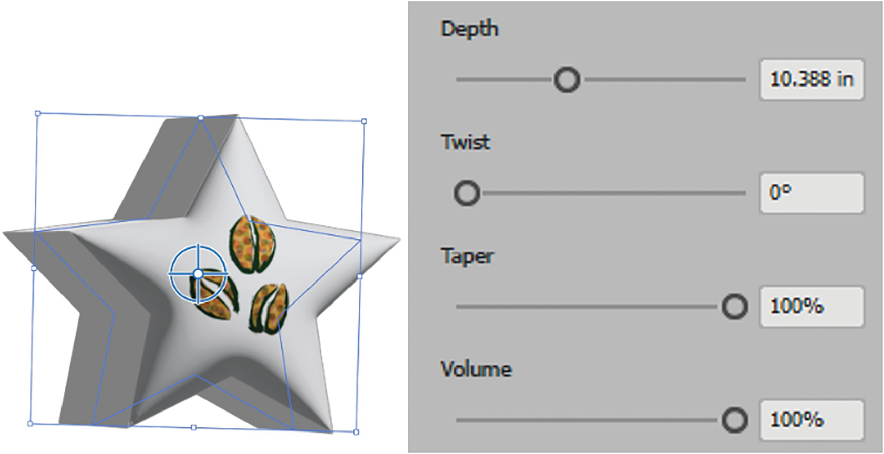
3D and Materials panel Object tab (Inflate), with object set to Depth Twist, Taper and Volume settings

3D and Materials panel Object tab (Inflate), with Inflate both sides option disabled and enabled
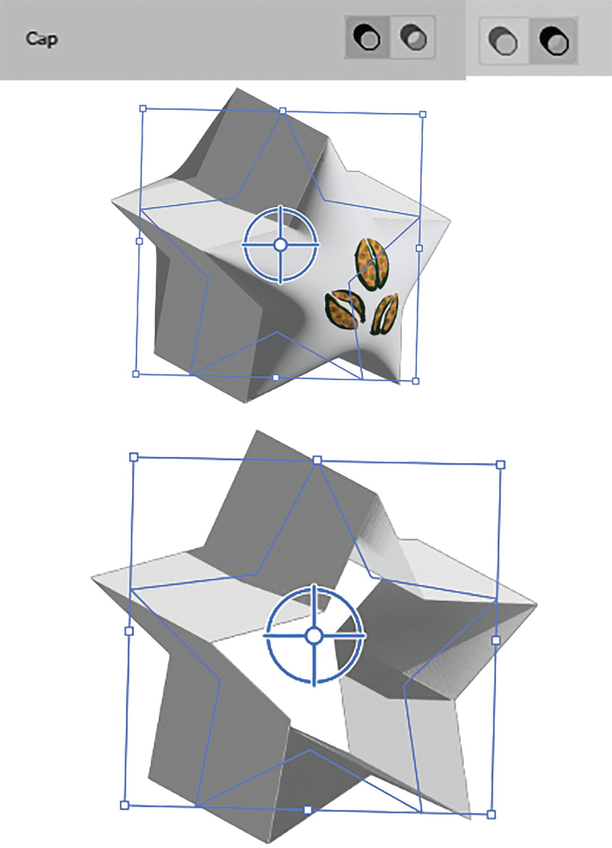
3D and Materials panel Object tab (Inflate), with Cap On and Cap Off preview

3D and Materials panel Object tab (Inflate) with Rotation presets and Perspective settings
Settings for the Materials, Lighting, and Render tabs are the same, and you can refer to the Rotate, Revolve, and Extrude & Bevel sections to learn more about these tabs in the panel. Materials will allow you to overlay symbols and have them appear over the material and not be hidden if you later add or remove a stroke from the object. With Inflate you can also adjust the shadows with your Lighting tab. Refer to Figure 13-202.

3D and Materials panel Lighting tab (Inflate) settings for lighting and adding shadows to object

Appearance panel with 3D effect added to Graphic Styles panel

Type with 3D Inflate effect applied

Paste your Illustrator graphics into Photoshop as Smart Object layers
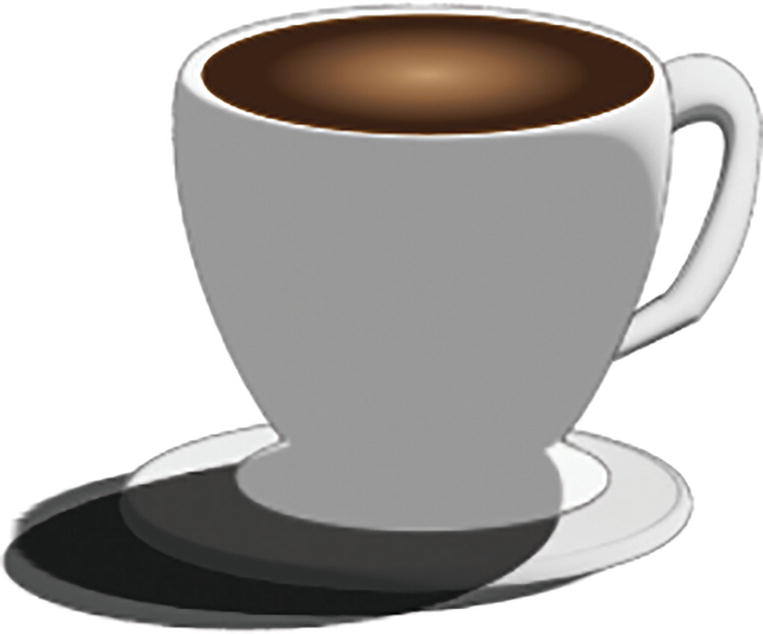
Example of coffee cup with various 3D effects from the 3D and Materials panel applied
To complete this design, I also added a circular ellipse with a gradient to cover the top of the cup and make it appear that there was liquid in the cup, with no effects applied. Refer to Figure 13-206.
With these new 3D features, while they work best with solid color fills and strokes, you can also use pattern and linear gradient swatches to create material-like effects that bend over the object, as you can see in this Inflate example. However, I would not recommend at this time using radial gradients in your designs as they can come out bitmapped. Refer to Figure 13-207.

The new and improved 3D settings work better with patterns and linear gradients on objects, and you can adjust opacity from the Control panel as well
With 3D effects in Illustrator, when you adjust the opacity using the Control panel it affects the object overall, and you will not see the back face with any contours as you would with behind actual 3d objects that are semi-transparent. Refer to Figure 13-207.
For information on acquiring more materials from the Substance Collection you can visit https://helpx.adobe.com/illustrator/using/create-3d-graphics.html?trackingid=YB1TGLWS&mv=in-product&mv2=ai.
Project: Blowing in the Wind, Part 9, Adding the House Using 3D Effects
To complete the landscape project of the girl at the farm, I will just show you how you can use your 3D and Materials panel to add a basic house shape, with a roof and a chimney, using the Extrude and Bevel option.

Landscape project with new objects added
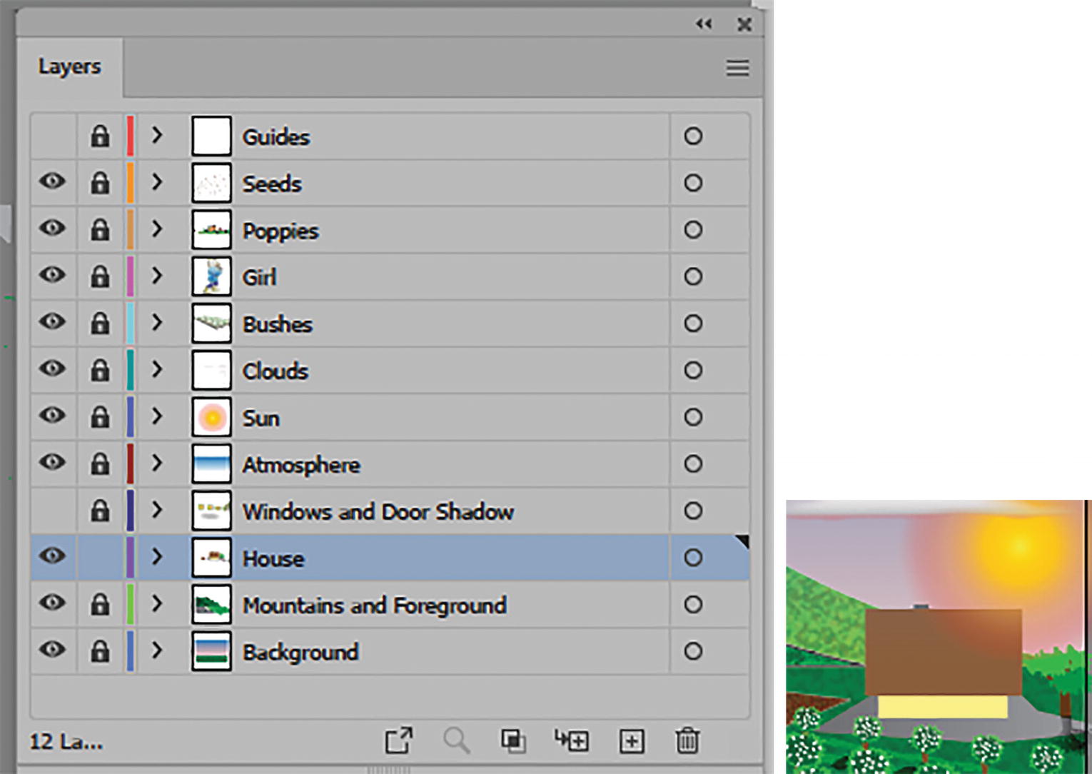
New paths added to the House layer
I also added a new layer called Windows and Door Shadow. You can leave that layer locked and hidden for now, as it does not apply to this part of the project.

Zoom tool

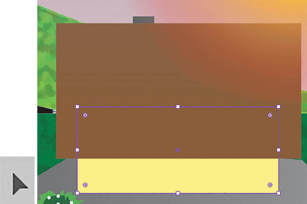
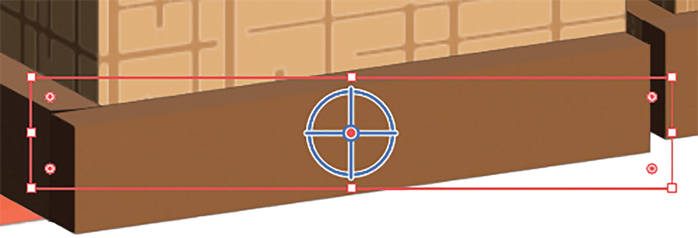
Select the yellow rectangle with the Selection tool

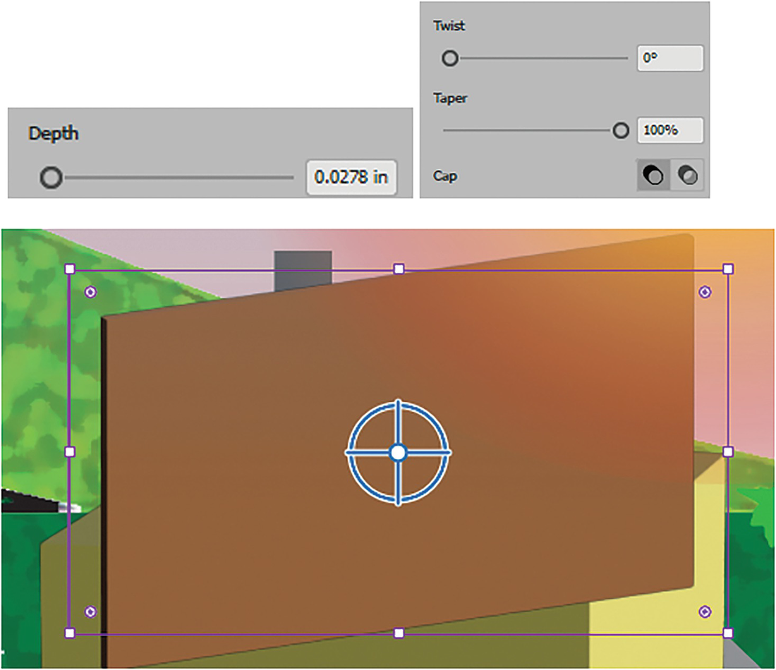
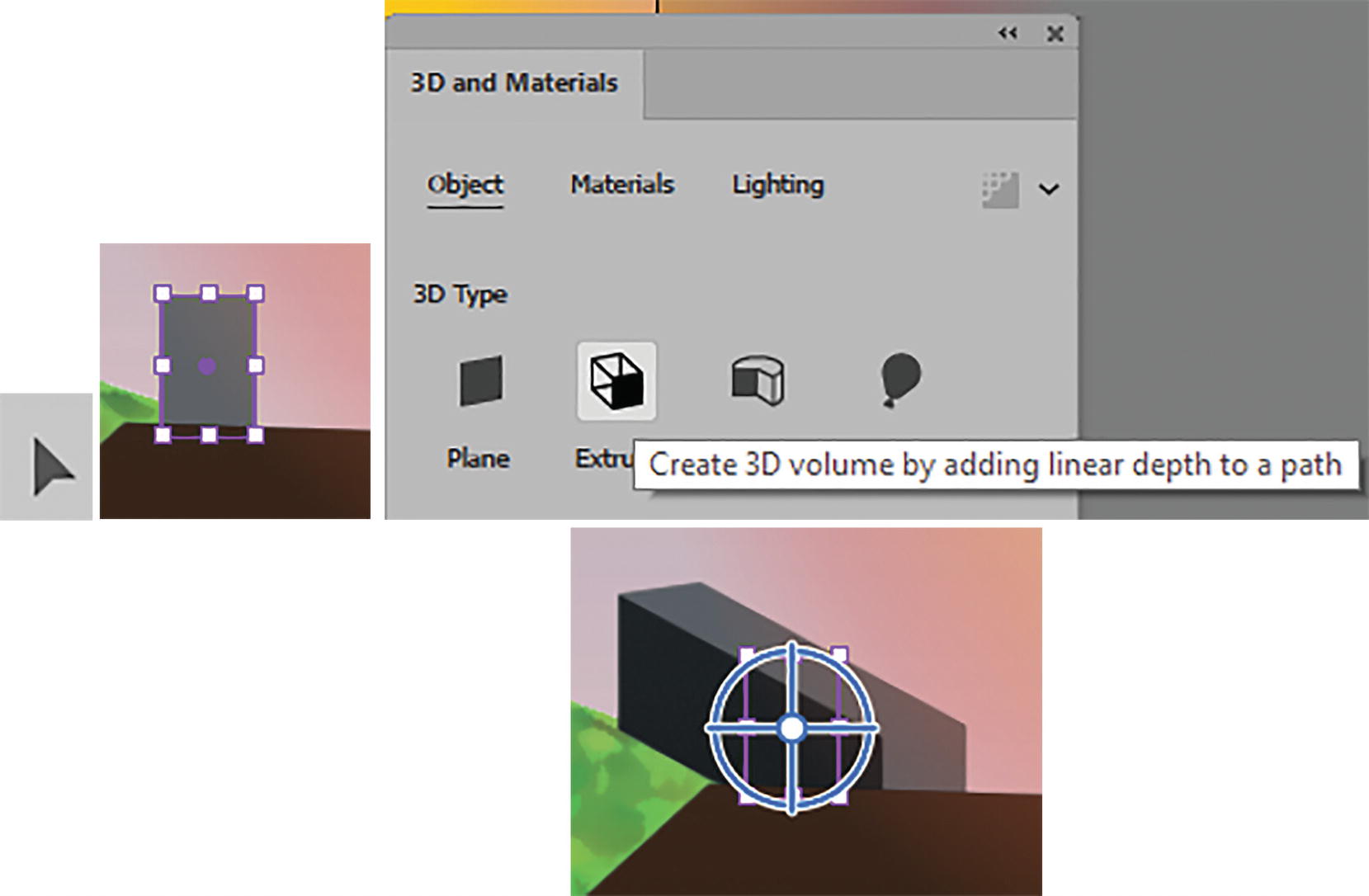
Use the Effect menu to apply a 3D and Materials ➤ Extrude & Bevel in the 3D and Materials panel

3D and Materials panel Object tab to set the depth and cap

3D and Materials panel Object tab, leave Bevel toggle off

3D and Materials panel Object tab, set the rotation settings and view result
I left everything else in the panel at the default settings.

Select the brown roof with the Selection tool

Choose the 3D Type Extrude from the 3D and Materials panel
At this point, it does not look much like a roof, but we will fix this.
3D and Materials panel, Object tab, set the depth and cap

3D and Materials panel, Object tab, set the bevel and review it

3D and Materials panel, Object tab, set the rotation and review it
No other settings were changed in the panel.
Use the Selection tool to select the chimney Choose the 3D Type Extrude from the 3D and Materials panel
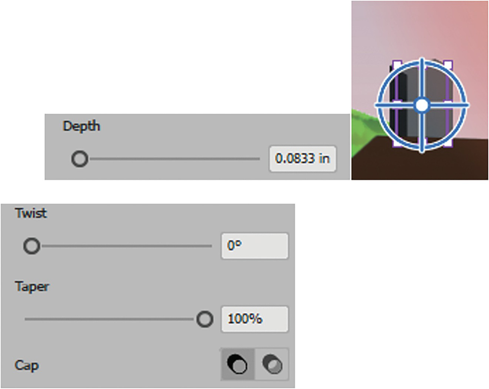
3D and Materials panel, Object tab, set the depth
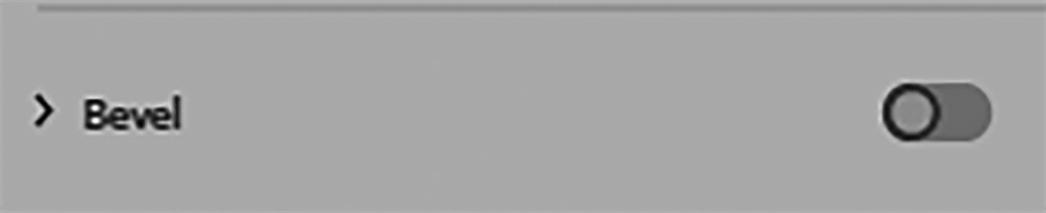
3D and Materials panel, Object tab, keep the Bevel toggle off

3D and Materials panel, Object tab, set the rotation
No other changes in the panel were made.
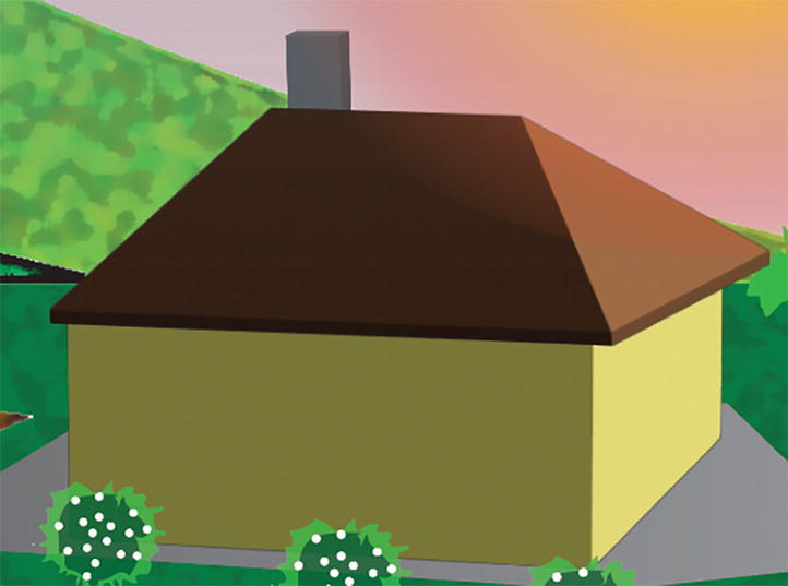
Review how the house currently looks
Lock the House layer

Turn on the visibility of the Windows and Door Shadow layer

View the settings and options for the shadow in the Transparency and Control panels
I could have used the 3D Bevel and Extrude option to create a shadow as well by using the Lighting tab on the various objects, but sometimes it is best to create a custom effect and blend it the way you want to. In complex areas of an illustration some shadows may not be as distinct at a distance. However, if the house were closer, more details could be added.
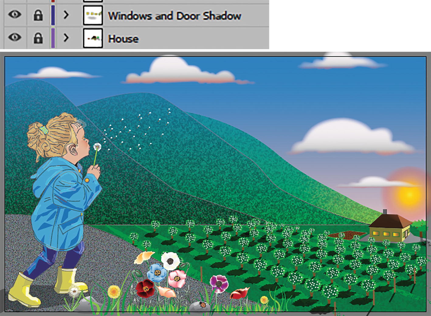
Lock the layers and view the completed image
The project is complete, and you can close any open files.
Graph Tools and 3D Effects for Creating Beginner Infographics

Toolbars panel graphing tools
One way you can put the data together quickly is to use Illustrator’s graphing tools.
While this is a separate topic, you can learn more about how to use these tools and some graphic suggestions at https://helpx.adobe.com/illustrator/using/graphs.html.
Project: Coffee Production Infographic Idea
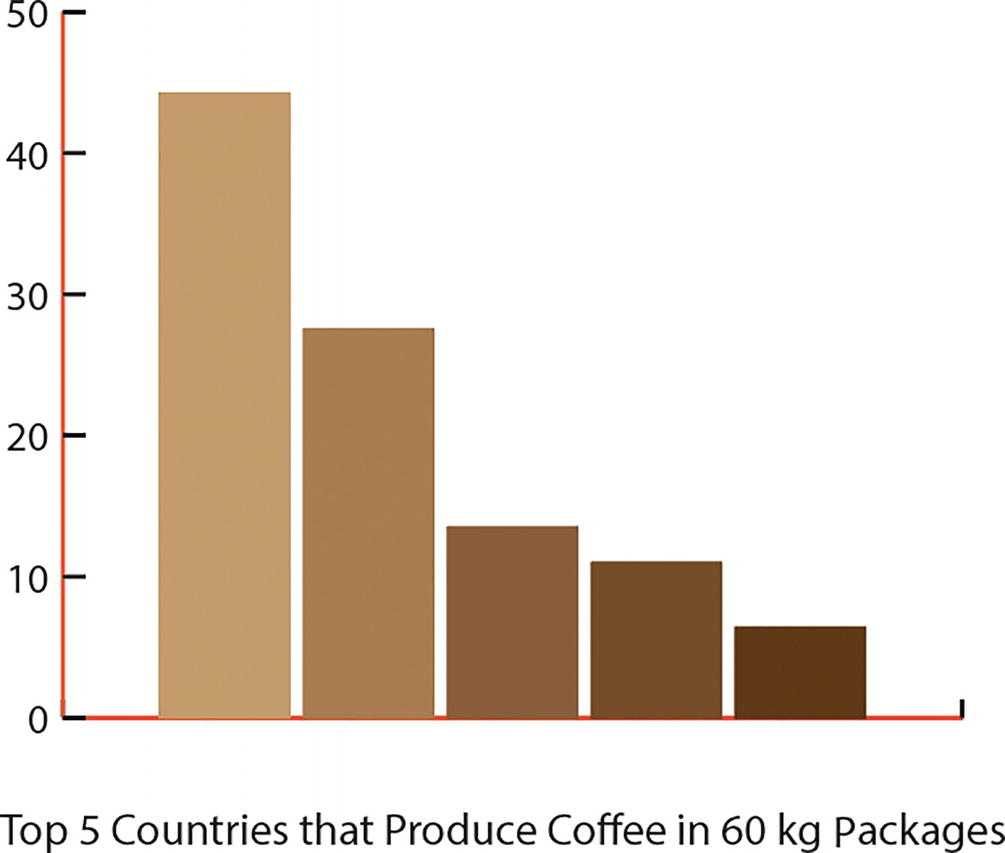
A simple column graph example

Infographic column graph with 3D effects
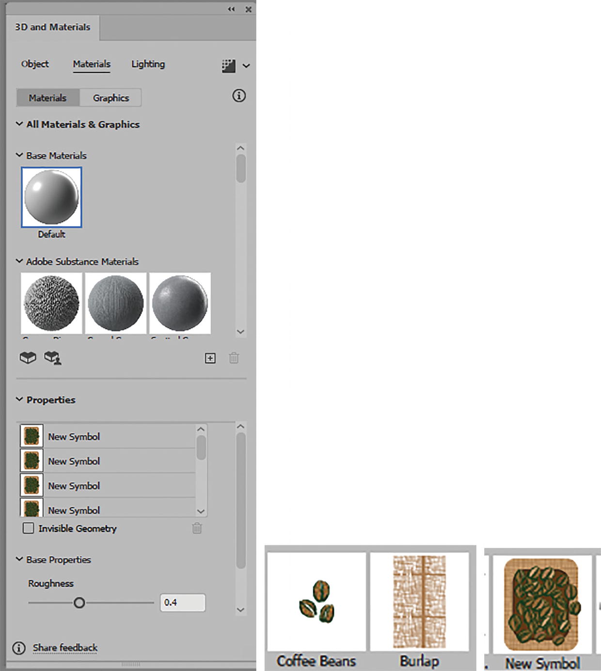
3D and Materials panel with many graphic symbols added to the Properties area, dragged into place on graph, and reordered in this area as well
This is something that I could never do with the 3D Classic effects.
Individual 3D wooden boards
If you want to look at this file in more detail, you can look at the file coffee_graph_final.ai.
While infographics can be complicated to initially research and dream up, Illustrator does make it easy to create them once you have a concept.
Summary
3D effects Extrude & Bevel, Rotate, and Revolve have been a part of Illustrator for some time. However, new and improved features have been added, like Materials and Inflate, that we can use in our illustrations and infographics to create some unique effects. Next, we will look at some other Adobe applications that we can use Photoshop or Illustrator graphics in to take your project to the next level.