Chapter Goal: Discover how to use the Illustrator Shape Warp Liquify tools correctly and discover that some tools are similar to what is found in Photoshop under Filter ➤ Liquify, though this filter is not required for this book.

Width and Liquify tools in the Toolbars panel
Maybe you have used these tools before but did not know how to modify their options; let’s look at that next.
You can find the projects for this chapter in the Chapter 5 folder.
Project: Warped Mandala Design

Mandala design and the original design in the Layers panel

Creating a copy layer of the pattern in the Layers panel

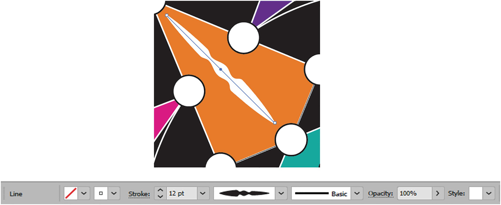
Selecting a line on the pattern
Width Tool (Shift + W)

Width tool and different tools in the Toolbars panel used to create lines

Control panel for the line segment when selected with the Selection tool

Default variable-width profiles in the Control panel

Variable width applied to the line
Use the Hand tool (spacebar) and Zoom tool if you need to see this area more closely. Refer to Figure 5-9. On your computer the preview of the variable width profile may vary slightly so refer to the names if you are unsure which to choose.

Use the Zoom tool when you need a closer look at the lines

Use the Width tool to select and widen parts of your line
You are now creating a custom variable-width profile.

Widen only one side of the line with the Width tool
Alt/Option-drag on the center of the point to create a copy of the point.
Hold down the Ctrl/CMD key if you need to move the stroke, and then release it to return to the Width tool. In this case, just leave the stroke where it is. Refer to Figure 5-12.

Use the Ctrl/CMD key with the Width tool when you need to move the line, and the pointer changes

Double-click on a point when the pointer changes, and enter the Width Point Edit dialog box
In the dialog box, set the Width Options for Side 1 and Side 2. The width is adjusted proportionately when the link is enabled. You can set the Total Width field, as well as select the Adjust Adjoining Width Points checkbox. Click OK to commit or the Cancel button to exit. Refer to Figure 5-13.
Once a width point is created, you can enter the dialog and delete the width point.
Make edits to the width point and move it on the path

The final line created with the Width Point tool

Adding a variable-width profile to the Control panel using the menu and dialog box

The custom variable-width profile is added to the menu
If you do not want to save this profile, you can delete it. Refer to Figure 5-18.

You can delete the profile from the Control panel’s Variable-Width Profile menu

You can reset the profiles from the Control panel’s Variable-Width Profile menu
However, this will not remove the custom profile from the line itself, only from the list.

Adjust the stroke weight so that you can see the custom variable-width profile
Additional Work with Line Segment Tool and Stroke Panel

Stroke panel with Show Options enabled

Select the line with the Selection tool

Adjust the direction of the profile using the Stroke panel

Changes in profile orientation using Flip Along or Flip Across

Lines currently selected are adjusted with the Stroke panel’s profile options
In the Stroke panel, for your own lines or stroke paths, besides changing the stroke weight and variable-width profile, you can also do the following:

Caps added to lines using the Stroke panel

Corner options added for Miter, Round, and Bevel with Miter Limit raised and lowered using the Stroke panel

Align strokes to Center, Inside, and Outside using the Stroke and Appearance panels

Variations of dashed lines are created using the Stroke panel options
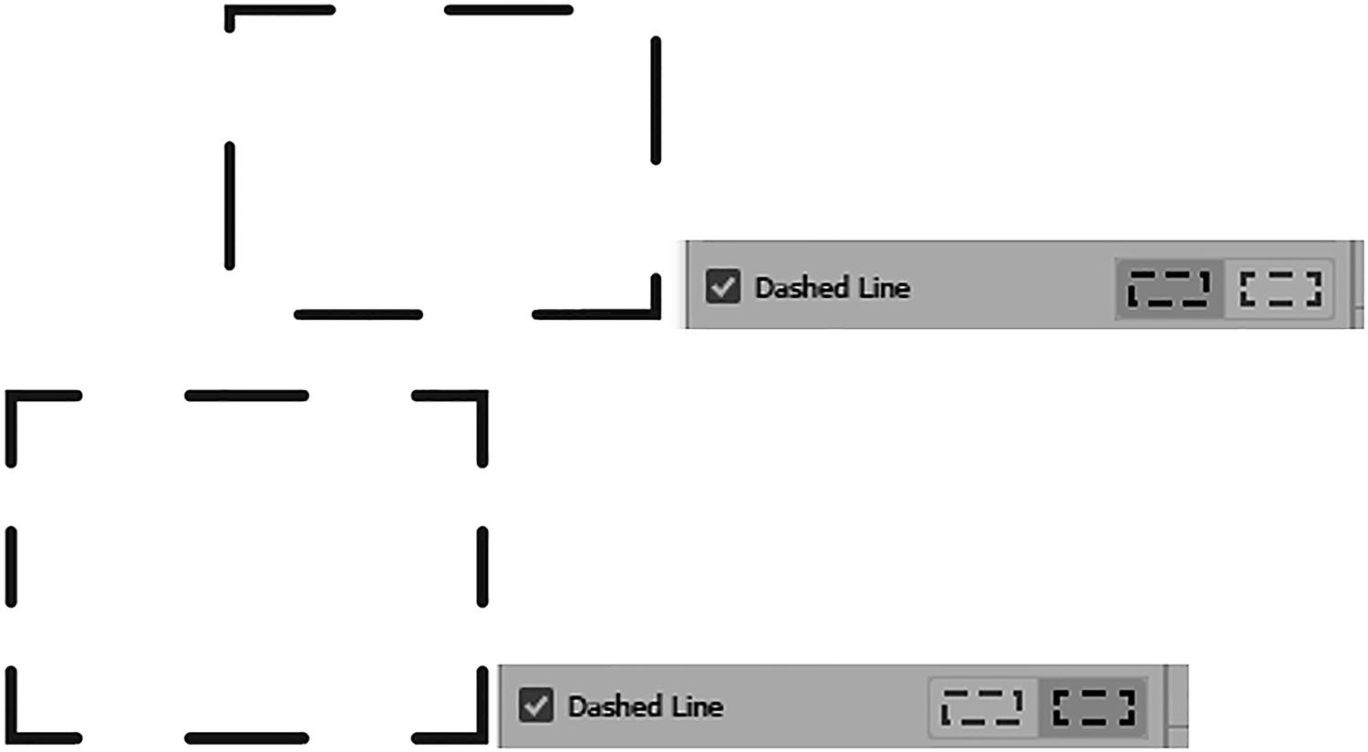
Additional dash line settings and the results they produce with dashes and gaps
Uncheck the Dashed Line checkbox if you want to return to a solid line.

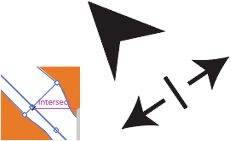
Arrowhead settings in the Strokes panel

Arrowheads Scale and Align settings in the Stroke panel
Align: You can extend the arrow tip beyond the end of the path or place the arrow tip at the end of the path. Refer to Figure 5-32.
You can used dashed lines with arrows as well. Refer to Figure 5-33.
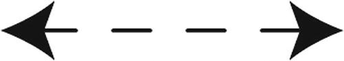
Arrowheads with dashed lines
Brushes Definition for the Current Variable-Width Profile
Setting brush definitions with the Control panel

Brush definition dropdown list in the Control panel
However, depending on the brush selected, it may not only reset the stroke weight, but also the variable-width profile and its orientation, which you then may have to reset in the Control panel. Also, not all brush definitions will work well with your custom width profile, so you may have to experiment. Or use Edit ➤ Undo (Ctrl/CMD+Z) a few times, or the History panel, to get the settings back to what they were previously.
We will look at brush definitions and variable-width profiles later in this chapter, and in a bit more detail in Chapter 8, where we’ll learn how brushes can be used with transparency.
If you want to change any of these strokes into a path, you can use Object ➤ Path ➤ Outline Stroke, and they will no longer be a single line segment. Use Edit ➤ Undo if this was not your intent. Refer to Figure 5-36.

Turning a line into an outline stroke object
Shape Warp (Liquify) Tools
The next set of tools affects the fill direction of the path, whether open or closed. If you used the Liquify filter in Photoshop, you should already be familiar with the Forward Warp tool, Twirl Clockwise tool, Pucker tool, and Bloat tool as far as how they affect a photograph. However, Illustrator has a few additional tools.
These tools will alter the shape permanently, which is why we are working on a copy of the object. If you make a mistake while warping, use Edit ➤ Undo (Ctrl/CMD+Z). Refer to Figure 5-37.

When creating a new design, always work on a copy to preserve the original artwork
Warp Tool (Shift + R)

Warp tool in the Toolbars panel
Make sure to select a path first with the Selection tool, and then select the Warp tool, so that you do not accidentally warp the other paths around it.

Use the Selection tool to select the ellipse before using the Warp tool
Drag the path inward or outward, using the Warp tool to alter the path
Then, try this on another area of the path, dragging inward.
Warp Options

Warp Tool Options dialog box
Width: This controls the width of the brush, in this case in inches. However, depending on what increments you set the rulers to, this may appear as points (pt). Or, you can set it by points from the dropdown list; 100 points or 1.3889 inches is the default. Refer to Figure 5-42.

The Warp Tool Options dialog box settings for the Width and Height fields can be adjusted using the text box or via the dropdown list for alternative increment settings
Height: This controls the height of the brush, in this case in inches. However, depending on what increments you set your rulers to, this may appear as points (pt). Or, you can set it by points from the dropdown list; 100 points or 1.3889 inches is the default. Refer to Figure 5-42.
Angle: (-180°, 0°, 180°) By default, the angle is set to 0°, but you can type in a different angle or choose one from the dropdown list. In this case, I left it at 0°. Refer to Figure 5-43.

Warp Tool Options dialog box settings for Angle field using text box or dropdown list, as well as Intensity settings
Intensity: This ranges from 1% to 100% and controls how fast the brush reacts to the pressure or length of time the mouse is held down, as we will see with other Shape Warp tools. By default, it is set to 50%, which I find is a good speed for the Warp tool, but too fast for other Liquify tools. Refer to Figure 5-43.
Use Pressure Pen: If enabled, it will gray out the Intensity field, and you will have to rely on the pressure of your stylus pen. If you do not have a pen, then make sure to leave this unchecked so that you can use your mouse instead. Refer to Figure 5-44.

Warp Tool Options dialog box with pressure pen enabled and disabled
Detail: When enabled, you can set the range from 1 to 10; the default is 2. If disabled, the path adds fewer points when the brush is dragged. Only a slight warp occurs. Refer to Figure 5-45.
Warp Tool Options dialog box with Detail checkbox disabled, and results produced
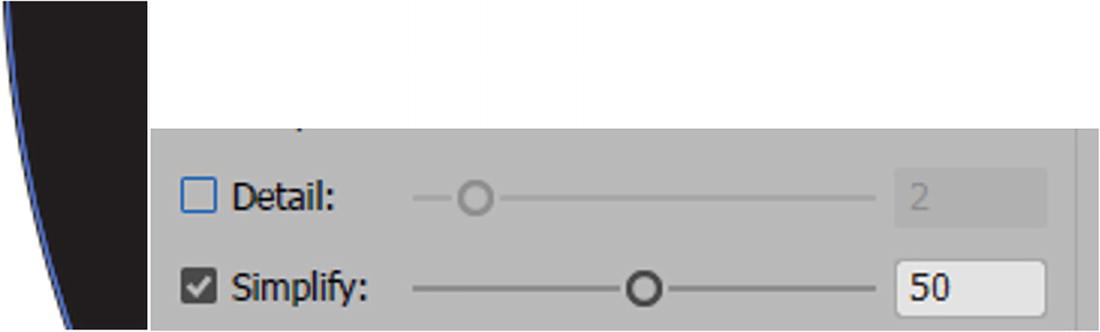
Simplify: When enabled, you can set the range from 0.2 to 100; the default is 50. If disabled, the path adds many points when the brush is dragged. Refer to Figure 5-46.

Warp Tool Options dialog box with Simplify checkbox disabled, and results produced

Warp Tool Options dialog box with Detail and Simplify checkboxes enabled, by default
When Show Brush Size is enabled, you can see the size of your brush as you work outside the dialog box. Refer to Figure 5-48.

Warp Tool Options dialog box with Show Brush Size checkbox enabled and info message
The info area lets you know that the brush size may be interactively changed by holding down the Alt/Option key before clicking with that tool. What this means is that when outside the dialog box, while the Alt/Option key is held down, you can drag the brush inward and outward to scale its width and height disproportionally. In addition, if you hold Alt/Option + Shift while you drag, you can size the width and height proportionately, and this setting can affect the other shape liquify brushes as well. Then release those keys to begin using the new brush size. Refer to Figure 5-48.
Click Reset to reset the brush, or OK to commit the settings, or Cancel to exit without saving the option changes. Refer to Figure 5-48.
I often work with the default brush or even a smaller brush size to make little edits to the path, as a larger warp brush can affect the whole shape and overwhelm it.

Design with Warp tool applied to the ellipse
Twirl Tool

Toolbars panel Twirl tool applied to a selected shape, twirling counterclockwise

With the Twirl tool twirling clockwise

Selecting a shape with the Selection tool; however, the brush size is too large, and the intensity is too fast, making for an undesirable twirl
Twirl Options

Twirl Tool Options dialog box
Many of the settings here for Global Brush Dimensions and Show Brush Size are the same as for the Warp tool options, so you can refer to that section for more details.

Twirl Tool Options dialog box Global Brush Dimensions settings

Twirl Tool Options dialog box default Twirl Options settings
Twirl Rate: Controls whether the spin is counterclockwise (0°–180°) or clockwise (-180°–0°); by default it is set to 40°, which is a counterclockwise spin. Refer to Figure 5-56.

Adjusting the Twirl Rate setting to move clockwise or counterclockwise produces different results

Results of twirl with Detail disabled and Simplify enabled

Results of twirl with Detail enabled and Simplify disabled
Click the Reset button to reset the Brush, or OK to commit the settings, or Cancel to exit without saving option changes. Refer to Figure 5-59.
Twirl Tool Options dialog box to reset settings, click OK, or click Cancel
In this case, I kept the default settings for the twirl options, with Detail and Simplify enabled, but, as mentioned earlier, I adjusted the brush’s width and height to 20pt and the intensity to 10% and clicked OK. Refer to Figure 5-54 and Figure 5-55.

Select a shape with the Selection tool and then use the Twirl tool with the new settings

The result of using the Twirl tool on the outer circles
Pucker Tool

Using the Toolbars panel Pucker tool on the selected star triangle

Use the Selection tool to select a path first, and then use the Pucker tool. If the brush is too large and the intensity is too high, you will get an undesirable result
Pucker Options

Pucker Tool Options dialog box
Many of the settings here for Global Brush Dimensions and Show Brush Size are the same as for the Warp tool options, so you can refer to that section for more details.

Pucker Tool Options dialog box Global Brush Dimensions settings

Pucker Tool Options dialog box, default pucker options

Results of pucker with Detail disabled and Simplify enabled

Results of pucker with Detail enabled and Simplify disabled
Click Reset to reset the brush, or OK to commit the settings, or Cancel to exit without saving option changes. Refer to Figure 5-69.

Pucker Tool Options dialog box to reset settings, click OK, or click Cancel
In this, case I kept the default settings for the pucker options, with Detail and Simplify enabled, but, as mentioned earlier, I adjusted the brush’s width and height to 50pt and intensity to 10% and clicked OK. Refer to Figure 5-65 and Figure 5-66.

Select a shape with the Selection tool and then use the Pucker tool with the new settings on that shape

The result of using the pucker tool on select star triangles. However some are left unselected and unchanged
Bloat Tool

Using the Bloat tool on a selected grouped object

When the Bloat tool is used with too large a brush and too high an intensity, you can get undesirable results
Bloat Options

Bloat Tool Options dialog box
Many of the settings here for Global Brush Dimensions and Show Brush Size are the same as for the Warp tool options, so you can refer to that section for more details.

Bloat Tool Options dialog box Global Brush Dimensions settings

Bloat Tool Options dialog box default bloat options
Detail: When enabled, you can set the range from 1 to 10; the default is 2. If disabled, fewer points are added to the path when the brush is dragged. Only a slight bloat occurs, and the center expands. Refer to Figure 5-77.

Results of bloat with Detail disabled and Simplify enabled
Simplify: When enabled, you can set the range from 0.2 to 100; the default is 50. If disabled, many points are added to the path when the brush is dragged or held down. Refer to Figure 5-78.

Results of bloat with Detail enabled and Simplify disabled
Click Reset to reset the brush, or OK to commit the settings, or Cancel to exit without saving option changes. Refer to Figure 5-79.

Bloat Tool Options dialog box to reset settings, click OK, or click Cancel
In this case, I kept the default settings for the bloat options, with Detail and Simplify enabled, but as mentioned earlier, I adjusted the brush’s width and height to 50pt and intensity to 10% and clicked OK. Refer to Figure 5-75 and Figure 5-76.

Selecting the grouped object with the Selection tool and using the Bloat tool with the new settings applied
Only through practice will you find the ideal bloat, and each will be slightly different, depending on how long you hold down your mouse. If you make a mistake, use Edit ➤ Undo and try again.
Scallop Tool

Using the Scallop tool from the Toolbars panel on a point of a colorful grouped star object

Select the grouped eight-point star object with the Selection tool
Scallop Options

Scallop Tool Options dialog box
Many of the settings here for Global Brush Dimensions and Show Brush Size are the same as for the Warp tool options, so you can refer to that section for more details.

Scallop Tool Options dialog box Global Brush Dimensions settings

Scallop Tool Options dialog box scallop options at default settings

Scallop options applied to point at different levels of complexity
Detail: When enabled, you can set the range from 1–10; the default is 2. If disabled, fewer points are added to the path when the brush is dragged. Only a slight scallop occurs but is not very noticeable. I keep it enabled. Refer to Figure 5-87.

Scallop Tool Options dialog box with setting of Detail disabled and enabled
Brush Affects Anchor Points: This setting, by default, is disabled. It becomes enabled when either the Brush Affects In Tangent Handles checkbox or Brush Affects Out Tangent Handles checkbox is disabled. Refer to Figure 5-88.

Scallop Tool Options dialog box with various checkboxes enabled and disabled, producing various results

The scallop appears more rounded when only the Brush Affects Anchor Points option is enabled
Brush Affects In Tangent Handles: Can be used separately or in combination with the Brush Affects Out Tangent Handles option. The scallop pulls inward and is more uneven. Refer to Figure 5-90.

Brush Affects In Tangent Handles produces a more lopsided scallop
Brush Affects Out Tangent Handles: Can be used separately or in combination with the Brush Affects In Tangent Handles or Brush Affects Anchor Points, but not both. The scallop pulls inward and is more uneven but is the mirror image of the In Tangent Hand Option. Refer to Figure 5-91.
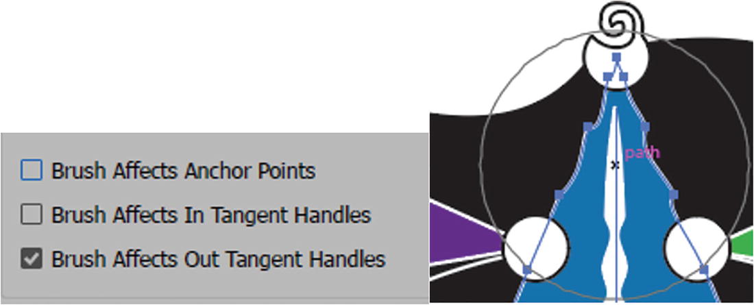
Brush Affects Out Tangent Handles produces a more lopsided scallop
Click Reset to reset the brush, or OK to commit the settings, or Cancel to exit without saving options changes. Refer to Figure 5-92.

Scallop Tool Options dialog box to reset settings, click OK, or click Cancel

Scallop Tool Options dialog box with current settings

Select the grouped star object with the Selection tool and use the Scallop tool with the new settings

The results of using the Scallop tool on four of the grouped stars points
Crystallize Tool

Use the Crystallize tool from the Toolbars panel on one of the selected grouped star’s points

Select the grouped star object with the Selection tool
Crystallize Options

Crystallize Tool Options dialog box
Many of the settings here for Global Brush Dimensions and Show Brush Size are the same as for the Warp tool Options, so you can refer to that section for more details.

Crystallize Tool Options dialog box Global Brush Dimensions settings

Crystallize Tool Options dialog box, Crystallize Options section with default settings
Complexity: 0–15, can be set using the textbox or its dropdown list. The default setting is 1.
Detail: When enabled, you can set the range from 1 to 10; the default is 2.
Brush Affects Anchor Points: Unlike Scallop, this option is enabled by default.
Brush Affects In Tangent Handles: By default this setting is disabled.
Brush Affects Out Tangent Handles: By default, this setting is disabled.
Click Reset to reset the brush, or OK to commit the settings, or Cancel to exit without saving option changes. Refer to Figure 5-101.

Crystallize Tool Options dialog box to reset settings, click OK, or click Cancel
In this case, I clicked Reset and lowered the intensity to 10%, then clicked OK. Refer to Figure 5-99.

Select the grouped star object with the Selection tool and use the Crystallize tool on one of the points

The results of using the Crystallize tool on four of the grouped stars’ points
Wrinkle Tool

Toolbars panel Wrinkle tool applied to one of the lines to warp it further
Select the line with the Selection tool
Wrinkle Options

Wrinkle Tool Options dialog box
Many of the settings here for Global Brush Dimensions and Show Brush Size are the same as for the Warp tool options, so you can refer to that section for more details.
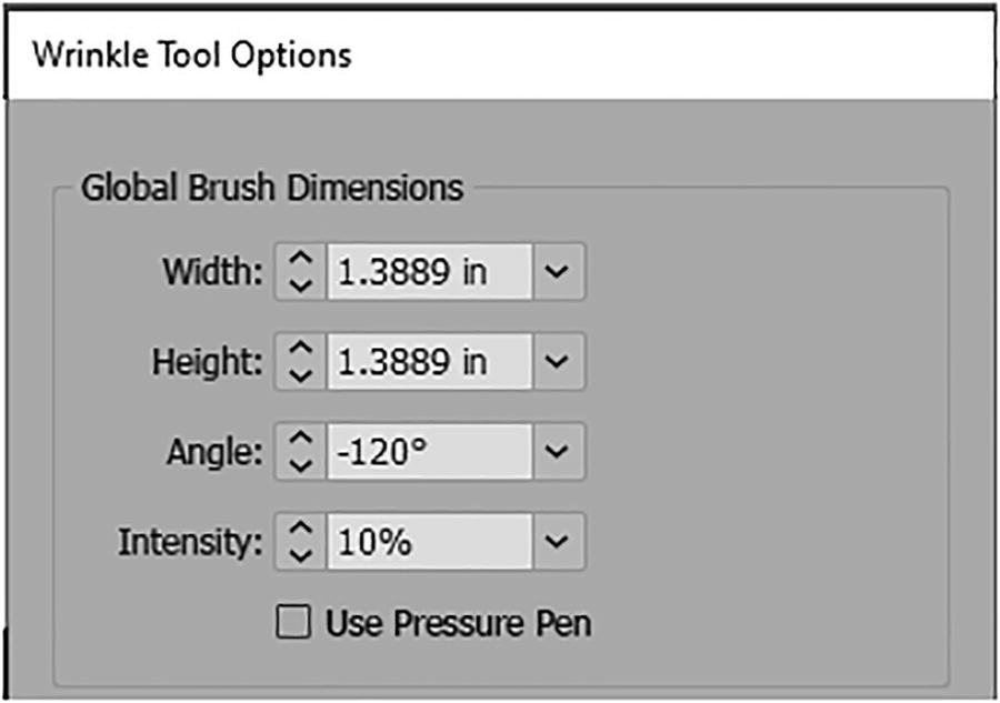
Wrinkle Tool Options dialog box with Global Brush Dimensions settings

Wrinkle Tool Options dialog box with Wrinkle Options section
Horizontal: 0%–100%; by default is set to 0. In this case I set it to 50% for a more defined wrinkle.
Vertical: 0%–100%; by default is set to 100%.
Complexity: 0–15, can be set using the textbox or its dropdown list. The default setting is 1.
Detail: When enabled, you can set the range from 1 to 10; the default is 2.
Brush Affects Anchor Points: By default is disabled.
Brush Affects In Tangent Handles: By default is enabled.
Brush Affects Out Tangent Handles: By default is enabled.
Click Reset to reset the brush, or OK to commit the settings, or Cancel to exit without saving option changes. Refer to Figure 5-109.

Wrinkle Tool Options dialog box to reset settings, click OK, or click Cancel
I clicked OK after making my changes. Refer to Figure 5-107 and Figure 5-108.

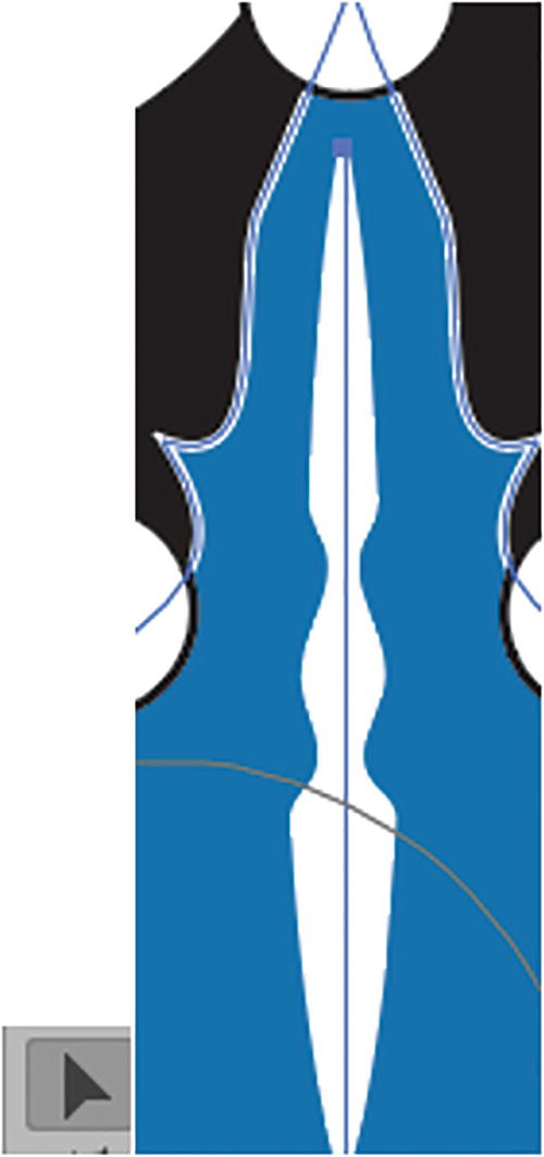
Select the line with the Selection tool and use the Wrinkle tool with the new settings

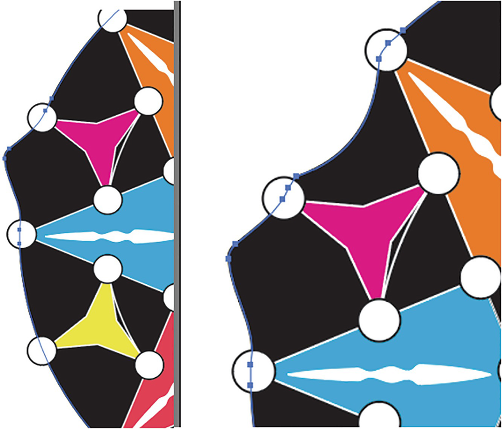
The result of using the Wrinkle tool on select lines, and then cleaning up using the Direct Selection tool to modify some of the points on the ellipse path
Afterward, you can always use the Direct Selection tool to modify individual points, or continue to warp and distort other paths on your own. Refer to Figure 5-111.
Save your document at this point. You can view my file, mandala_width_shape_warp_final.ai, for reference.
It should be mentioned, as in Chapter 4, that like the Puppet Warp if you want to use these Warp Liquify tools on a symbol, you must first break the link with the symbols in the library before you can edit the group path. Refer to Figure 5-112.

Symbols will need to be broken before you can use the Liquify tools on them
We’ll look at symbols in Chapters 6, 12, and 13.
For selected type, you need to convert the text to Type ➤ Create Outlines before you can use these tools. Refer to Figure 5-113.

Type will need to be in outlines before you can use the Liquify tools on them
We’ll look at type in Chapters 9 and 10.
Later, in Chapter 9 and 11, we will look at some less destructive ways of altering your objects with warps.
Project: Blowing in the Wind, Part 3
To continue with our project of the young girl at the farm, let’s make the lines in the field more organic looking by adding a variable-width profile and a brush definition to the strokes.

The current project with the Mountains and Foreground layer unlocked in the Layers panel
In this example, you will find the layer Mountains and Foreground unlocked; you need to select this layer so that you can edit it.

Use the Selection tool to Shift + Click on lines in the path

Use the Control panel to see that multiple stroke weights have been selected

Use the Control panel to set the Variable-Width Profile field
This will cause the lines to be thin on the ends but thicker in the middle.

Use the Control panel to set the Brush Definition field
You may notice, at this point, that your Stroke Weight and Variable-Width Profile fields may switch back to the default of 1 point and Uniform.

The Brush Definitions field resets the Stroke Weight and Variable Width Profile settings
In this case, it is better to add the brush definition first and then the variable-width profile, and lastly the stroke weight.

Reset the Variable-Width Profile field again in the Control panel for all selected lines

Reset the Stroke Weight for each selected line:
Line 1: 8pt
Line 2: 6pt
Line 3: 5pt
Line 4: 4pt
Line 5: 3pt
Line 6: 3pt
Line 7: 2pt
Line 8: 1pt

The field with the updated rows is ready for planting

Lock the layers when you are done with the project
Later, in Chapter 8, we’ll take a closer look at some of the brush strokes on the girl.
You can save and close any open projects at this point.
Summary
Illustrator’s Liquify tools allow you to alter or change the shape of single paths in grouped objects very quickly. With the Width tool, you can modify and stretch parts of a brush stroke on a shape that you can save as a preset and later access in the Control panel or Stroke panel. Next, we’ll look at another tool that can assist you in blending two shapes or symbols together and create a variety of morphed transitions.