
Chapter 21. Accelerometers
Accelerometers are a good introduction to a class of electronic components called microelectromechanical systems (MEMS). An accelerometer can either be one-axis, two-axis, or three-axis. This designates how many different directions it can simultaneously measure acceleration. Most gaming devices have three-axis accelerometers.
As far as game development is concerned, acceleration values are typically delivered to your program via an API with units in multiples of g. One g is equal to the acceleration caused by gravity on the Earth, or 9.8 m/s2. Let’s pretend that we have a one-axis accelerometer and we orient it such that the axis is pointing toward the center of the earth. It would register 1g. Now, if we travel far away from any mass, such that there is no gravity, the accelerometer will read 0. If we then accelerate it such that in one second it goes from 0 m/s to 9.8 m/s, the accelerometer will read a steady 1g during that one-second interval. Indeed, it is impossible to tell the difference between acceleration due to gravity and acceleration due to changing velocity.
Real-life motion is generally nonsteady. Depending on your application’s goals, you might have to apply different smoothing functions such as high-pass or low-pass filters. This amounts to digital signal processing, a topic that has consumed entire texts. One example we can recommend is Digital Signal Processing: A Computer Science Perspective by Jonathan Y. Stein (Wiley).
Also, many accelerometers have a method to set the polling rate, or the number of times per second that the program requests updates from the accelerometer. This is called frequency and is given in hertz (Hz). This parameter can be used to enhance the performance of the program when fine resolution of the acceleration over time is not needed.
When you accept input from an accelerometer—or do any other kind of signal processing—you have to accept that input won’t come precisely when you want it. The operating systems normally used for gaming—Windows, OS X, Linux—are not real-time environments. This means that although you set the polling rate at once a second, this guarantees only that the data will be delivered no sooner than once a second. If something distracts the operating system, such as the arrival of packets on the network, the signal you get from the accelerometer may be delayed.
Accelerometer Theory
The way in which MEMS measure accelerometers is more basic in principle than you may think. The major accomplishment is miniaturizing the technology until it can fit inside a computer chip! To clearly illustrate the basic principle, we will first show you the mechanics of it in the macro-scale version of a known mass and spring. Let’s say you build something like the contraption shown in Figure 21-1 and take it on an elevator in an area where there is no gravity. We’ll worry about the effects of gravity in a minute.
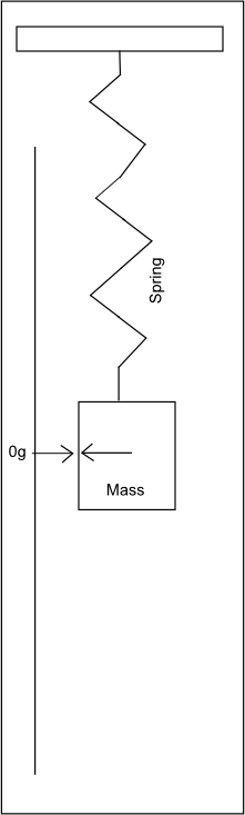
As you can see, the device consists of a known mass at the end of a spring next to a measuring stick. When the elevator is not accelerating, the mass is at the 0 mark. When the elevator accelerates up or down, the mass at the end of the spring resists that acceleration and tends to stay at rest. This is Newton’s first law in action. Inertial loading causes the spring to stretch or compress. If the elevator is accelerating upward, the mass will cause the spring to stretch downward. Recall from Chapter 3 that the force acting on a spring is linearly dependent on the displacement of the mass via the equation:
| Fn = kd |
We can directly measure the displacement, d, so we can determine the force in that direction, n. As the mass is known, voilà!
| an = m/Fn |
As an aside, the fact that you can tell that you are accelerating without having to look outside the elevator is what makes this a “noninertial frame of reference,” as discussed in Chapter 2. No worries if you don’t totally understand that; it isn’t important for what we are discussing here.
Now, let’s put our elevator back on earth. With the same device, the mass will not be at 0 even if the elevator is not accelerating because gravity is pulling it down. Previously we used units of inches, which we then converted to force and finally to acceleration. However, we now have a direct measure of the acceleration due to gravity and could easily place a mark on where the mass is and call it 1g. Also we could place marks along the ruler at the same intervals. Now, we accelerate the elevator upward at 9.8 m/s2. The mass should move down the scale to 2g, and anyone standing in the elevator would feel twice as heavy as normal.
Let’s say we wanted to accelerate the elevator downward at 9.8 m/s2. We could easily do this by just releasing the brakes and letting gravity do the work. Now in freefall we don’t feel gravity at all, right? That’s because the downward acceleration is canceling the acceleration due to gravity. The mass will be back at 0 just like out in space, far from any gravitational bodies. It is for this reason, and not a lack of gravity, that astronauts float around. They are in freefall around the earth.
Lastly, if we accelerate the elevator downward at 2g, the mass would move to the −1g mark on the ruler. This is because the downward acceleration is now overwhelming gravity. Those in the elevator would find themselves standing on the ceiling feeling exactly as they would standing on the ground! In fact, one of Einstein’s accomplishments was showing that it is impossible to distinguish gravity from inertial accelerations. We’ll leave the details of that for independent study and get back to accelerometers in the form of MEMS.
MEMS Accelerometers
Micro-scale accelerometers are not that much different from the machine previously described but generally use a cantilevered beam instead of a spring. To track more than one axis, sometimes three discrete accelerometers are placed out of plane with respect to one another. Alternatively, more complex models use elements that can sense all three directions within a single integrated sensor. These generally give better results.
The only important difference from the aforementioned examples, besides MEMS being thousands of times smaller in scale than the mass and spring, is how to measure the deflection of the test mass. There are three common methods employed in accelerometers. For most game devices where extreme accuracy isn’t required, the deflection is usually measured as a change in capacitance. This is somewhat the same way that capacitive touch screens work, as described in Chapter 20, and is shown in Figure 21-2.
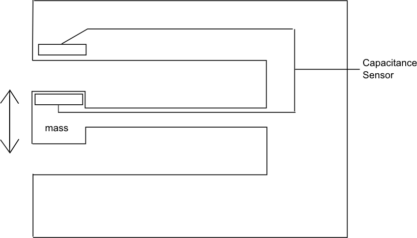
The beam deflects under the influence of the external accelerations of the test mass and brings two charged plates farther or closer together. This changes the capacitance of the system. This change can then be calibrated to the imposed acceleration.
Other methods include integrating a piezoresister in the beam itself so that the deflection of the beam changes the resistance of the circuit. Although this ultimately gives better results, these are harder to manufacture. For the most demanding applications, there are accelerometers using piezoelectric elements based on quartz crystals. These are very sensitive even during high-frequency changes in acceleration but are generally not used in sensing human-input motion.
Common Accelerometer Specifications
To help you better experiment with accelerometers, we’ve collected the specifications on a few of the most common accelerometers in use at the time of writing. The future may hold cheap accelerometers based on quantum tunneling that can provide almost limitless accuracy, but Table 21-1 outlines what you’ll generally be working with for now.
|
Device |
Accelerometer chip |
Sensor range |
Sampling rate |
|
iPhone/iPad/ Motorola Droid |
LIS331D |
±2g* |
100 Hz or 400 Hz |
|
Nintendo Wii |
ADXl330 |
±3g |
x-/y-axis: 0.5 Hz to 1600 Hz z-axis: 0.5 Hz to 550 Hz |
|
Sony Six Axis |
Not published |
±3g |
100 Hz |
Note
The chip LIS221D is actually capable of two modes. One mode is ±2g and the other is ±8g. This is dynamically selectable according to the chips datasheet; however, neither iOS nor Android allows developers to change the mode through the API.
The 2g limit for phones can cause problems when you’re attempting to record motion. This limitation will be discussed later in this chapter. The larger range of Wii and Sony controllers demonstrate that they are dedicated to gaming where larger accelerations are expected.
Data Clipping
The human arm is capable of exceeding the ±2g range of the iPhone’s sensor easily. The values reported by the API will actually exceed 2g up to about 2.3g. The accuracy of these values that exceed the specification is unknown. Regardless, they are probably at least as accurate as the option of trying to recreate the data, so if required they can be used. All values above this upper limit will be reported as the upper limit such that if you graphed the values, they would look like Figure 21-3.
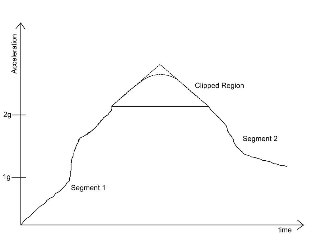
There are several different ways to handle data clipping. One is to discard the data and alert the user that he has exceeded the available range. Another is to attempt to recreate the missing data. If you are recording the data for later processing, you can use both segment 1 and segment 2 to fit the curve between the point at which the data began to be clipped and the point in which meaningful data collection is resumed. This is highly application dependent, and the curve used to fit the data will have to be matched to the activity at hand. If you are recording the data for later processing, you can use both segment 1 and segment 2 to give your data.
If you are attempting to process the signal in real time, you’ll have only segment 1 to work from. This could result in a discontinuity when meaningful data collection resumes, and you’ll have to decide how to deal with that given the particulars of what you are doing with the data.
Sensing Orientation
Sensing rotation in three degrees of freedom amounts to sensing a rigid body’s orientation and is a complex problem that cannot be fully resolved using only accelerometers. Think about holding the device vertically. If you rotate the device about the axis described by the gravity vector, none of the accelerometers will measure any change in the force acting on their test masses. We can’t measure that degree of freedom. To do so, we’d need to fix a gyroscope to the device, and even these run into problems when a body is free to rotate about all three axes. See Chapter 11 for a discussion on Euler angles.
Now let’s discuss what we can accomplish. First, Figure 21-4 demonstrates the coordinate system we’ll use; the actual coordinate system used will be determined by the manufacturer of your device, so make sure to check its documentation.
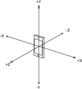
Now if we make some assumptions based on how a user will hold our device, we can determine some “gross” orientations. For illustration, Table 21-2 gives some idea of what each value would be for each gross direction, assuming the coordinate system shown in Figure 21-4.
|
Device orientation |
X |
Y |
Z |
|
Face down on table |
0 |
0 |
1 |
|
Face up on table |
0 |
0 |
−1 |
|
Horizontal on table, right side down |
1 |
0 |
0 |
|
Horizontal on table, left side down |
−1 |
0 |
0 |
|
Vertical on table, bottom down |
0 |
−1 |
0 |
|
Vertical on table, top down |
0 |
1 |
0 |
There are a few things to note here. First, if you were to hold the phone in these orientations with your hand, the accelerometer is sensitive enough to pick up small deviations from true vertical. We are considering these the “gross” orientations such that these small deviations should be ignored.
Sensing Tilt
Although we can’t determine exactly what angle the user is holding the phone about all three axes, we can pick one axis, assume that it is pointing down, and then find the change in the angle from that assumption over time. For instance, if the phone is lying on a table, the average acceleration in the z-direction will be −1, and in the other directions, 0. Even if the user spins the phone, the values will remain as previously indicated and we cannot sense that rotation. However, if the user lifts one edge from the table—we’ll call this tilting it—then the accelerometer will register different values. Some of the acceleration due to gravity will act on the other two axes. By sensing this change, an accelerometer will allow us to determine at what angle the device is tilted.
Using Tilt to Control a Sprite
Here we will show you how to implement code for a simple game that asks the user to move an avatar to a target by tilting the phone. First, we will briefly show an example of determining the rotation about a single axis. Let’s assume we have an accelerometer rotated at some arbitrary angle, α, which is what our algorithm will solve for. As previously discussed, accelerometers generally report values as multiples of near earth gravity, g. For the following example, we are concerned only with the x- and y-axis values, ax and ay, respectively. If the device were in the “upright” position, then ax would equal 0 and ay would equal 1. After rotating the device, we’d see different values that are related to our angle α by use of the arctangent function. In this case, because the single-argument atan function included in most programming languages doesn’t differentiate between diametrically opposed directions, it is beneficial to use the two-argument function. The relevant C code is as follows:
#define PI 3.14159

float find2dAngle(void){

    //LOCAL VARIABLES
    float alpha,
    double ax, ay;

    //POLL ACCELEROMETER FOR ACCELERATIONS, API SPECIFIC
    ax = getXacceleration();
    ay = getYacceleration();

    //FIND ANGLE
    alpha = atan2(ay,ax);

    if (alpha >= 0){
        alpha = alpha * (180/PI);
    else {
        alpha = alpha * (-180/PI) + 180;
    }

    return alpha;
}
This is pretty straightforward, but there are a few things to point out. First, the way
in which your program will get results from the accelerometer will vary greatly between
platforms, so we have encapsulated that API-specific code in a getXacceleration() function. In fact, most operating systems will be
continuously polling the accelerometer in a separate thread, so you’ll have to have a
logical operator that tells your accelerometer object when you actually want to see those
values passed to your program. Example Objective-C code for the accelerometer in the iPhone
will be shown later. Secondly, you’ll notice that we are using an if statement that changes the radians to degrees in such a way as to return
proper 0°–360° answers. This avoids having to pay attention to the sign, as
atan2 returns only answers between 0° and 180°, using a negative value
to represent the other half of the range. For example, an output of 0° means the device is
vertical, an output of 90° means the device is rotated 90° to the left, and an output of
180° means the device is upside down.
Now let’s extend this to two dimensions. This will tell us not only how far the phone is from vertical about one axis, but its inclination about the y-axis as well.
Two Degrees of Freedom
Now let’s say that we want to develop a game in which we control a sprite moving in a 2D world. The user would hold the device as if it were lying on a table and look down from above. He or she would then tilt the phone out of that plane to get the sprite to move in the desired direction. The fraction of gravity that the accelerometer is now experiencing in the x- and y-directions will be inputs into our simulation.
The example will be demonstrated using Objective-C code for the iPhone, and we’ll be using the Qwartz2D graphics framework. If you aren’t familiar with Objective-C, don’t worry—we’ll explain what we are doing in each step, and you can port that code to whatever language you are working in.
The first step will be to set up our accelerometer. In this case we are going to initialize it in our tiltViewController.m file so that we have:
- (void)viewDidLoad
{
    UIAccelerometer *accelerometer = [UIAccelerometer sharedAccelerometer];
    accelerometer.delegate  = self;
    accelerometer.updateInterval = kPollingRate;
    [super viewDidLoad];
}
The important concept here is that we have defined a name for our accelerometer object,
accelerometer, and we have set its updateInterval property to kPollingRate. This constant was defined in tiltViewController.h as (1.0f/60.0f), which
corresponds to 60 Hz. In other words, this tells the operating system to update our
program’s accelerometer object 60 times a second. Also in tiltViewController.m, we write what happens when the accelerometer object gets
updated via the accelerometer’s didAccelerate: function
as follows:
- (void)accelerometer:(UIAccelerometer *)accelerometer
didAccelerate:(UIAcceleration *)acceleration{
    [(SpriteView *)self.view setAcceleration:acceleration];
    [(SpriteView *)self.view draw];
}
This function is called every time the acceleration object is updated and does two
things. First, it takes the acceleration data from the accelerometer and passes it to the
SpriteView class, which we’ll talk about in a second.
Then it tells the SpriteView to go ahead and redraw
itself.
The SpriteView class is where the action happens and
consists of a header file, SpriteView.h, where we
define the following global variables:
UIImage *spriteA pointer to the image that will be used to represent our sprite on the screen.
currentPosThe position on the screen where we want the sprite to be drawn.
prevPosThe previous position of the sprite on the screen. We will use this to tell the draw function what parts of the screen need to be redrawn.
UIAcceleration *accelerationA special Objective-C data type to hold data from the accelerometer.
CGFloat xVelocityandCGFloat yVelocityFloat variables to hold the current velocity in the x-direction and y-direction, respectively.
CGFloat convertXandCGFloat convertYFloat variables to hold the ratios for converting our physics engine’s results in meters to pixels based on an assumed world size.
Additionally, we’ve defined the following global constants:
gNear earth gravity value, set at 9.8 m/s2. This will convert the accelerometer’s values from g to m/s2 for use in calculating velocity. This can also be tuned to represent an arbitrary acceleration instead of just using gravity as the force (e.g., percent of jet engine thrust).
kWorldHeightandkWorldWidthThese values are used to allow the programmer to change the assumed world dimensions. Higher values mean each pixel is a greater distance in meters. The world will always be scaled to fit on the screen, so a large world means the sprite will appear to move slower (a few pixels at a time) for a given acceleration. Note that our current code doesn’t scale the sprite.
Now we’ll show you how we use these variables in SpriteView.m to move our sprite on our screen as a result of the accelerometer
values. First, we have some initialization to do, which takes place in the initWithCoder: method that runs the first time the view is
loaded:
-(id)initWithCoder:(NSCoder *)coder {
    if((self = [super initWithCoder:coder])){
        self.sprite = [UIImage imageNamed:@"sprite.png"];
        self.currentPos = CGPointMake((self.bounds.size.width / 2.0f) +
(sprite.size.width / 2.0f), (self.bounds.size.height /2.0f)+(sprite.size.height /2.0f));
        xVelocity = 0.0f;
        yVelcoity = 0.0f;

        convertX = self.bounds.size.width / kWorldWidth;
        convertY = self.bounds.size.height / kWorldHeight;

    }
    return self;
}
Most of this is pretty straightforward. We tell our program where to find the sprite
image we’ve chosen and set its initial position to the center of the screen. We also set its
initial velocity to 0 in both directions. We then go ahead and initialize our convertX and convertY
variables based on the self.bounds.size property, which
gives the bounds of the view in pixels. We’ll show exactly how this affects our program
later. Next, we’ll write a custom mutator for the
CurrentPos variable:
- (void)setCurrentPos:(CGPoint)newPos {
    prevPos = currentPos;
    currentPos = newPos;

    if(currentPos.x <0){
        currentPos.x = 0;
        xVelocity = 0.0f;
    }
    if(currentPos.y <0){
        currentPos.y = 0;
        yVelcoity = 0.0f;
    }
    if(currentPos.x > self.bounds.size.width - sprite.size.width){
        currentPos.x = self.bounds.size.width - sprite.size.width;
        xVelocity = 0.0f;
    }
    if(currentPos.y > self.bounds.size.height - sprite.size.height){
        currentPos.y = self.bounds.size.height - sprite.size.height;
        yVelocity = 0.0f;
    }

    CGRect curSpriteRect = CGRectMake(currentPos.x, currentPos.y,
currentPos.x+sprite.size.width, currentPos.y+sprite.size.height);
    CGRect prevSpriteRect = CGRectMake(prevPos.x, prevPos.y,
prevPos.x+sprite.size.width, currentPos.y+sprite.size.height);
    [self setNeedsDisplayInRect:CGRectUnion(curSpriteRect, prevSpriteRect)];

}
In case you are unfamiliar with Objective-C, when you define a class instance variable
it will automatically define a mutator that simply updates the value of the variable to the
value you are passing it. However, in the preceding example we are overriding that mutator
to do some additional work. The first thing we do is to set the prevPos variable to the current position of the sprite and then update the
currentPos with the value the mutator was given.
However, our physics engine isn’t going to include collision response with the screen
boundaries, so we go on to check if the sprite has reached the screen edge. If so, we simply
tell the program to leave it on the edge and to set the velocity in that direction to 0.
Lastly, we define a couple of rectangles based on the new position of the sprite and the old
position of the sprite. After we union those rectangles together, we tell the operating
system to redraw the screen in that area with the setNeedDisplayInRect: method. As you might recall, our accelerometer object is
calling the draw method every time it updates, and it is
in this method that we will put our physics engine:
- (void)draw {
    static NSDate *lastUpdateTime;

    if (lastUpdateTime != nil) {
        NSTimeInterval secondsSinceUpdate = -([lastUpdateTime
timeIntervalSinceNow]); //calculates interval in seconds from last update

        //Calculate displacement
        CGFloat deltaX = xVelocity * secondsSinceUpdate +
((acceleration.x*g*secondsSinceUpdate*secondsSinceUpdate)/2); // METERS
        CGFloat deltaY = yVelocity * secondsSinceUpdate +
((acceleration.y*g*secondsSinceUpdate*secondsSinceUpdate)/2); // METERS

        //Converts from meters to pixels based on defined World size
        deltaX = deltaX * convertX;
        deltaY = deltaY * convertY;

        //Calculate new velocity at new current position
        xVelocity = xVelocity + acceleration.x * g * secondsSinceUpdate; //assumes
acceleration was constant over last update interval
        yVelocity = yVelocity - (acceleration.y * g * secondsSinceUpdate); //assumes
acceleration was constant over last update interval

        //Mutate currentPos which will update screen
        self.currentPos = CGPointMake(self.currentPos.x + deltaX,
self.currentPos.y + deltaY);

    }

    [lastUpdateTime release];
    lastUpdateTime = [[NSDate alloc] init];

}
Previously, we discussed issues with timing when working with accelerometer data. In
this case, Objective-C makes it very easy to get the correct elapsed time in seconds. We
first define a static variable, lastUpdateTime, as an
NSDate type. This type has a built-in function to give
the time interval in seconds from now, which we assign to an NSTimeInterval variable. Skipping down to the last two lines, we are simply
updating the last update time by releasing and reinitializing the variable. As it is static,
it will remain even after the function returns. If you are using a lower-level language, you
might have to write your own timeIntervalSinceNow
function that takes into account the particular clock frequency of the system.
Now that we have our time interval in seconds, we can calculate our new position. Recall from Chapter 2:
| s2 = s1 + v1 t + (a t2)/2 |
which we have rearranged to be:
| Δs = s2 − s1 = v1 t + (a t2)/2 |
This gets programmed as:
CGFloat deltaX = xVelocity * secondsSinceUpdate + ((acceleration.x*g*secondsSinceUpdate*secondsSinceUpdate)/2); // METERSWe then convert this displacement in meters to displacement in pixels using an appropriate ratio for the size of our world. Before we can move on, we have to calculate our new velocity at our new position. So we again assume the acceleration as constant over the update interval, and recalling:
| v2 = v1 + a Δt |
from Chapter 2, we can solve for the new xVelocity with:
xVelocity = xVelocity + acceleration.x * g * secondsSinceUpdate;As you can see from the complete method description, the code of the y-direction is
similar. Finally, we call the currentPos mutator to set
the new position based on the change in displacements. Recall that this is a custom mutator
that also tells the operating system to update the display. After the draw method is finished, the accelerometer waits 1/60 of a
second and then calls it again. You could extend this program by adding in friction, fluid
resistance, and collisions with the screen boundaries using the methods outlined in the
other chapters of this book.