

Video
LIGHT, LENSES, CAMERAS, AND RECORDERS
You can walk into almost any electronics store or large discount store and walk out with a really nice camcorder that will record directly to a DVD, digital tape format, or flash drive for about $500. Can you start making video projects? Yes! Will they look professional, like we see on TV? Probably not! Although these cameras can get some great shots, most of them work with automatic features that prevent you from having control over the video. Also, unless you know about the basics of how the camera works and what the features can do for you, the video you shoot will probably look like it was shot by an amateur. Learning what equipment to use and how to use its features will help get you to the point of shooting truly outstanding video and making professional-looking projects.
Like any craftsperson or artist, a successful videographer wants the most information possible about the tools of the trade. Knowing how a piece of equipment works reveals its limitations and its possibilities. To become truly proficient at creating video, a TV videographer sooner or later has to learn the technical things too often left just to the engineers and maintenance staff. As camcorders move toward simpler and simpler operation, it actually becomes more important for the user to know how each part of the system works. Relying on the camera to do all the thinking reduces the level of creativity by reducing the attention to detail. To master the craft—indeed, the art—of video, the videographer must master, and understand, the tools in every respect. This book will give the videographer a good start on the road to that understanding.
The medium of TV involves three basic forms of communication: sight, sound, and motion. The basic tools for creating these for TV are a camera, a recording device, a microphone, and a source of illumination. In this chapter and Chapters 9 and 10, the basic elements of each piece of field production equipment are introduced. This chapter discusses the camera, with its lens, and the recorder—the two most important elements in capturing sight and motion. Chapter 9 deals with microphones and recording techniques—the sound element. Chapter 10 presents light sources and their control—the one component necessary to accomplish any type of photography or videography.
Video: The Process of Image Acquisition
There is no end to the machines, gadgets, and accessories that a videographer can consider prized possessions on a shoot. There is a big difference, however, between a basic set of gear and the ideal set of gear. Although budgets will determine the type and quantity of equipment, there will always be several items that simply cannot be left out. These may be of the lowest or highest quality, but they constitute the minimum needed to do the job.
Today’s TV videographers have a wide range of equipment available; therefore, it is hard to provide a definitive list. The following list will satisfy job requirements at the minimum standards of quality almost anywhere:
• Camera with lens
• Digital recorder, either mounted on/in the camera or separate (standalone); some camcorders will have built-in videotape recorders
• Four to six hours of battery power
• Tripod with fluid head
• Set of three AC-powered (120 V) location lights and AC extension cords
• Camera-mounted light, with batteries and cables
• Omnidirectional hand mic
• Two-lavalier mics
This chapter will introduce you to most of the basic forms of equipment used in portable video today. As more and more manufacturers and newly developed technologies enter the market, no one book can describe them all in detail. The following text will go through a basic description of how a typical device works. It is always a good idea to get the service and operating manuals for the equipment you will be using and read them thoroughly to truly understand that particular piece of gear. Today’s marketplace underscores that thought. With a growing number of recording formats and delivery systems, a videographer can easily be in a situation where nothing seems compatible. Just keeping up with the changing technologies is a full-time job. Understanding them is a career. But the basics of how video works will always be the same.
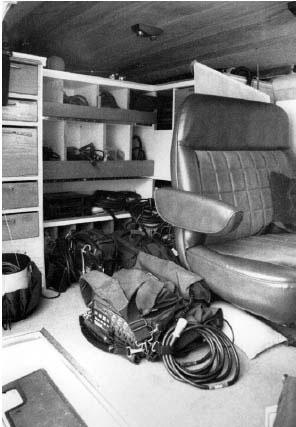
FIGURE 8.1
The interior of a production van, viewed through the side door. Custom shelves are made to organize and store equipment.
PRINCIPLES OF LENS OPERATION
The lens of the human eye is a truly amazing mechanism for directing and focusing light on the light-sensitive rods and cones in the back of our eyes. In video cameras, the zoom lens tries to perform the same tasks. While our eyes have a single lens, video lenses are complicated devices with many individual pieces of glass that can be physically moved to direct, focus, and magnify the light from images in front of it. If the lens cannot focus properly, the picture is fuzzy; if it cannot transmit light efficiently, then the picture is dark or distorted.
Lens Components
No less valuable than the eye’s lens is the lens on a camera. While most discussions of video equipment center on the camera and tape machines, the lens is a crucial part of the image-gathering process. A high-quality lens can make the best camera the best performer, and a poor-quality lens can leave the camera’s picture out of focus and distorted. The eye has one simple lens that does amazing things. The camera needs several lenses, called elements, to duplicate the complex workings of the eye. Nonzoom lenses used in still photography, as well as in the newer DSLR cameras for video and some high end digital cinema cameras, are made up of as many as five elements in two groups that properly place an image on the recording surface or focal plane. A zoom lens, which is used on most TV cameras, has 13 or more elements.
A lens is basically two prisms joined together. If the prisms are joined at their apexes, they form a concave lens that refracts light out from the center. If joined at the base, they form a convex lens that converges the light to a single point.
Light refracted through a prism can be broken down into areas of different wavelengths. Even after prisms are joined to make lenses, small defects can cause aberrations in the sharpness and color of the image by not transmitting all frequencies evenly. By combining groups of concave and convex lenses and using special coatings, almost all the defects of any single lens can be overcome. Such defects as chromatic and spherical aberrations, curvature of the field, distortion, flare, and astigmatism are all corrected by the many elements contained in the average TV lens. Each of the elements in the lens serves a specific purpose in controlling the quality and quantity of the visual information.
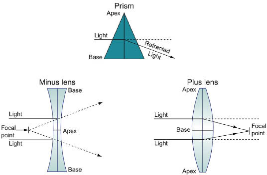
FIGURE 8.2
Prisms and light paths.
FOCAL LENGTH
The distance from the optical center of the primary lens to the point where the light converges on the focal plane (the principal focal point) is the focal length of a lens. On professional TV camera lenses, the focal length setting can be read off the zoom portion of the lens. The focal length determines the field of view of the lens. A lens with a very short focal length has a very wide field of view and is called a wide-angle lens. A lens with a long focal length has a narrow field of view and is called a telephoto lens. Focal lengths are measured in millimeters (mm). The average TV zoom lens starts at about 8 mm and goes to 100 mm or more. Focal lengths between 4.5 mm (available in some wide-angle lenses) and 25 mm are considered to be wide-angle fields of view. From 25 mm to 75 mm, a lens is said to have a normal field of view, meaning that the lens sees things in a way similar to the way your eye does. From 75 mm to the longest focal lengths available, the lens has a narrow field of view, the image is magnified, and the setting is referred to as telephoto.
The field of view of a lens is often expressed as the horizontal angle of view and is measured in degrees. The widest setting of many professional lenses is about 8 mm. This focal length represents an angle of view of about 50 degrees, which would have a view about 6 feet wide of a wall 6 feet from the camera. A wide-angle lens, about 5.5 mm, has an angle of view of about 75 degrees, which sees an area 10 feet wide of a wall 6 feet from the camera. Similarly, a lens of 300 mm would have an angle of view of less than 2 degrees and would cover only a span of about 1 foot of a wall 50 feet from the camera.
The advantage of a zoom lens over lenses of fixed focal lengths is that the focal length can be set at any point from 8 mm all the way to 100 mm, or whatever the parameters happen to be on that lens. We will say more about the zoom lens a little later. While fixed focal length lenses, sometimes called prime lenses, are generally of a higher quality than zoom lenses and are used on DSLRs and high end digital cinema cameras.
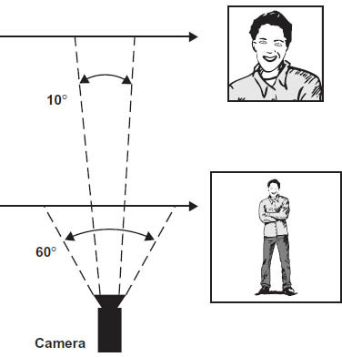
FIGURE 8.3
A wide field of view (60°) would see the subject head to toe. A narrow field of view (10°) would see only the head and shoulders of that same subject.
FOCUS
Another set of elements in the lens determines the sharpness of the image sent to the principle focus or focal plane. These elements are usually at the front of the lens. By moving these elements further away or closer to the remaining elements, objects at different distances to the focal plane can be brought into sharp focus. The point of focus in front of the camera determines an area called the plane of focus. Almost all lenses have focusing marks on the barrel that read in feet and meters. If the focus barrel is turned in order to line up the number 10 on the focus mark, then the plane of focus is 10 feet from the camera (more precisely, from the focal plane of the camera). Often objects at other distances are also in focus with the barrel set at 10 feet. The range of acceptable focus in front of and behind the plane of focus is called the depth of field; on older 35mm still cameras, this information can be read right off the lens for any focal plane setting. Video lenses do not have this convenience; the eye must judge what the range is. (See Figure 8.4.)
Three factors have an effect on the depth of field for any chosen plane of focus: the focal length, the iris opening, and the distance from the camera. As the focal length increases, the depth of field decreases; as the iris is opened up, the depth of field decreases. (See Table 8.1.) As the lens is focused on objects closer and closer to the camera, the depth of field also decreases. The greatest depth of field occurs with wide-angle focal lengths with the iris opening very small and the lens focused at infinity. The shortest depth of field comes at telephoto settings, with the iris wide open and the lens focused at its minimum focus point.
Take a video camera outside and practice adjusting the zoom and focus, first in full sun and then in deep shade. Notice how much more depth of field you have in the sunny areas, even as you zoom in. Also, notice how much easier it is to stay in focus when the lens is at its widest setting. As you begin to use a video camera more, you will get used to combining the effects of focal length, focus, and iris to achieve the results you want.
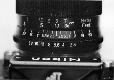
FIGURE 8.4
The still camera lens has its focus set at 10 feet and its f-stop at f5.6. The middle scale on the lens shows the depth of field for those settings. At f5.6, everything from 30 feet to approximately 7 feet will be in focus.
Although it is still rare to see an auto-focus function on a professional style camera, it is standard on consumer and prosumer (a more sophisticated or professional videographer, e.g., a wedding videographer) cameras. The auto-focus function can make shooting moving objects easier to keep in focus, but as we have mentioned earlier, a true professional likes to maintain as much control as possible over the tools. As anyone who has used an auto-focus camera can attest, the system doesn’t always do what you want it to—a situation unacceptable to a professional.
The hyperfocal distance of a lens is the distance from the lens to the first point where an object is in focus when the lens is focused at infinity. When shooting news or any uncontrolled action where there is little time or ability to focus properly, this number is very useful. The number will vary depending on the iris setting and focal length, but at full wide angle, the iris settings will have little effect on the hyperfocal distance. This translates into the ability to focus the lens at infinity and know that everything at the hyperfocal distance or beyond is in focus.
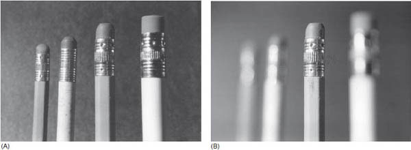
FIGURE 8.5
(A) Deep depth of field. (B) Shallow depth of field. Frame (A) was made with the iris at f22. Everything is the same in frame (B), except the iris is at f2.8. The same exposure was maintained by adding neutral-density filters to the camera lens.
TABLE 8.1 Factors That Affect Depth of Field
| Factor | Effect on Depth of Field |
| Focal length | As focal length increases, depth of field increases. |
| Iris opening | As the iris opening increases, depth of field decreases. |
| Subject to camera distance | As the distance from the subject to the camera increases, depth of field increases. |
MACROFOCUS
Although every lens can focus on infinity, each lens has a limit on how close it can focus. This varies from one type of lens to another and is called the minimum object distance (MOD). For a high-quality broadcast lens, such as the Canon HJ40x14B, that distance is about 2.8 meters, but it is 10 mm (about ½ inch) with the macrofocus engaged. Most professional TV zoom lenses have a minimum distance similar to this. Therefore, to get a really close-up shot of a small object, a very valuable feature to have on the lens is a macrofocusing ring. The macrofocus is usually a pull-out knob on the rear area of the lens barrel that allows a rotation of the rear elements inside the lens to change the focus distance.
It is possible to macrofocus as close as the surface of the front element of the lens itself when it’s at the wide-angle focal length. The macrofocus can be used with the lens focused at any point and set at any focal length.
However, with the macrofocus engaged, the focal length cannot be adjusted without disturbing the focus of the picture. In macro, a zoom lens in effect becomes a fixed focal length lens because of this limitation.
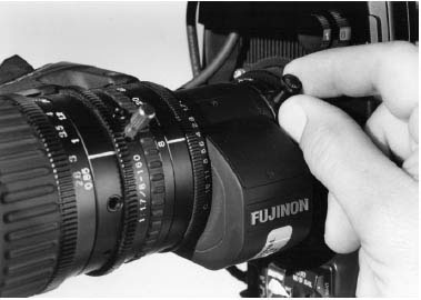
FIGURE 8.6
On this Fujinon lens, the small macrofocus knob at the base of the lens must be pulled out slightly to allow its rotation. When rotated, the lens operates in the macrofocus mode.
Creative videographers have found unlimited uses for the macrofocus. The macro’s effect on the front focus and zoom can be used to creative advantage. With a lens set in macro, any change of the focal length changes the point of focus, which gives you the ability to use the zoom to change focus. This abnormal behavior can lead to some very unusual shots. An understanding of the relationships among the various elements that make up a TV lens can lead to interesting shots that enhance the visual quality of the product.
ASPECT RATIO
Even though lenses are round, the pictures they make are rectangular. The ratio between the width and the height of the TV picture is always the same. All analog TV cameras had an aspect ratio of 4:3 (or 1.33:1 in cinema terms): for every four units of width in the picture, its height will be three units. This limitation becomes most noticeable when, for instance, a videographer tries to shoot a still picture of a military officer printed in a book. The still photographer turned the camera on its side to get the portrait of the general head to toe. For the video camera to see this picture head to toe, extra space is needed on either side of the photo, because the aspect ratios do not match. The full shot of the general from the book will probably be just head and shoulders or a tilt up from boots to face to avoid empty or undesirable space on either side of the photo. Learning to see things as the video camera sees them means getting used to seeing everything in this 4:3 aspect ratio.
Video shot for high-definition TV (HDTV) is in the 16:9 ratio. This wider ratio affords a picture that is similar to a 35 mm slide in shape. It is also closer to what we see in movie theaters. It is superior to the old analog 4:3 aspect ratio because 16:9 is more like our normal human way of seeing things. Our field of vision is more rectangular than the old 4:3, which is closer to a square shape.
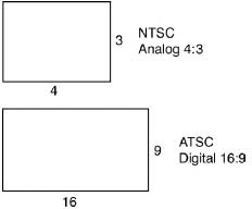
FIGURE 8.7
NTSC analog aspect ratio of 4:3, compared with ATSC digital aspect ratio of 16:9.
IRIS
Every lens has an aperture for controlling the amount of light passed on to the focal plane. Just like the mechanism in the eye that controls the amount of light, this aperture is referred to as an iris. The iris consists of a series of overlapping metal leaves or fins that can be rotated one way to make the hole very small or rotated the other way to make the hole very large. The efficiency of a lens to pass light is referred to as its speed. A “fast” lens can transmit a large amount of light, whereas a slow lens transmits a much smaller amount of light. The speed is measured in f-stops. An f-stop is the ratio between the size of the aperture and the focal length of the lens. F-stops are a standardized way of measuring the passage of light on every lens; the numbers refer to a specific amount of light. A lens set at f8 gives the same amount of light no matter which camera or format of recording. The differences in lens speeds come from how wide the iris can be opened. The smaller the f-stop number, the more light the lens transmits. A lens that can go to f2 is not as fast as a lens that can go to f1.4.
Most lenses used for video shooting range from f16 to f1.8. Each f-stop shown on the lens represents twice as much light as the one before it, or half as much as the one after it. The f-stops would normally be f16, f11, f8, f5.6, f4, f2.8, f2, and f1.4. An iris at f8 lets in twice the amount of light as a setting of f11, but only half as much light as f5.6. If the exposure is increased by one stop, you are allowing in twice as much light. The smallest f-stop number tells you how “fast” the lens is. The typical lens mentioned before can only go to f1.8, which is only one-quarter of a stop faster than f2 and three-quarters of a stop, or 75 percent, darker than the next full stop of f1.4. A small increase in the fastest f-stop does not greatly affect the lens’s ability to gather light, particularly in low-light situations. For most cameras, a lens faster than f1.4 would not show any improvement in gathering light. Each camera has an internal optical system; most of them are rated at f1.4. Newer ENG cameras have internal speeds of around f1.2. Lens makers are making lenses with speeds to match this, but both cameras and lenses of this type are very expensive. It does no good to place an expensive fast lens like an f1.2 on a camera that can only receive an f1.4 amount of light.
Video lenses allow the increase or decrease of exposures by fractions of stops because the iris is free moving and can be set at any point within the range of the lens. At the stopped-down end of the iris (the smallest aperture), there often is a position labeled C, for cap. When the iris is in this position, no light at all is being sent to the camera. This feature protects certain workings of the camera when not in use and also shows the camera true black. (See the discussion on black balance later in this chapter.)
Most lenses operate best at the middle range of their f-stops. The optimum is usually f5.6 and one stop up or down from there. Only in very controlled situations is it possible to always operate at optimum. At f5.6 the flaws that may be inherent in the lens will be at their minimum and all the lens elements will be performing at the best degree possible. The iris has an effect not only on the exposure but on the look of the shot as well. The f-stop setting is only one factor in setting up a shot and does not have to be dictated by lighting conditions.
AUTO-IRIS
All video lenses have servos that control the iris setting. A servo is an electronically powered gear that adjusts the setting. A switch can easily change the iris from manual to auto to allow the camera to set the proper exposure for you. This can be a help or a hindrance to the videographer. Another small button on the lens allows the operator to briefly put the lens into auto-iris only for the time the button is depressed. This method is generally the choice of most videographers, because it can set an exposure quickly but not stay in auto all the time, where it is likely to roam. Roaming is where the iris reacts to everything that comes into the frame. In a scene with much action or many camera moves, an auto-iris can fluctuate wildly as dark-clothed subjects and bright light sources pass through the frame. The result is an amateurish scene with an exposure that fluctuates from dark to light with every movement in the frame. Most scenes require only one constant exposure setting. Autoiris also does not guarantee the proper exposure. It merely “averages” the scene exposure between the brightest and darkest elements. Auto-iris would leave the face of an interview subject wearing dark clothes shot against a dark background overexposed because of this. The videographer determines which element is most important (often the face of the subject) and exposes for that element. Once again, allowing a machine to make critical decisions can leave the videographer at a creative disadvantage.
ZOOM LENSES
Lenses used by many DSLR (digital single-lens reflex cameras) videographers and a great many cinematographers often have a fixed focal length. Traditionally designed video cameras almost always are equipped with a zoom lens, a lens that can change focal lengths through a series of sliding elements within the lens. Zoom lenses permit changing the field of view without changing the point of focus or the aperture. Unlike the two optical groups that make up a fixed focal length lens, four different optical groups make up a zoom lens (see Figure 8.8):
• The focusing group gathers the light into a sharp, clear image.
• The variator group moves inside the lens to change the image size from wide angle to telephoto.
• The compensator group moves with the variator group to keep the image in focus and reduce aberrations caused by the first two groups.
• The prime lens group focuses the image on the recording surface, such as film or a TV camera chip.
When setting up a shot for proper focus, zoom all the way into the object you determine to be the focus plane, focus the lens, and then zoom out to the desired focal length for shooting.
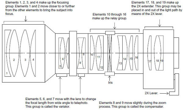
FIGURE 8.8
Optical groups for a typical TV zoom lens.
TV zoom lenses also come with a box of electronic servos formed into a hand grip and attached to the side of the lens. (See Figure 8.9.)
The servos drive a series of gears that turn the zoom barrel as well as the iris ring (mentioned earlier). A rocker-style switch on top of the hand grip controls the zoom servo, which allows you to move the elements continuously at speeds from a mere crawl to a fast snap zoom. In some professional video cameras, the zoom and the iris can be operated electrically from a remote location with the proper cable and control unit.
By using an extension cable, the zoom control can be operated from anywhere the operator wants within the length of the cable. The power zoom can be turned off on all lenses, leaving the lens to manual control. By simply twisting the zoom portion of the lens tube, you can adjust the focal length or accomplish zooms. This method of zooming generally cannot be done as smoothly as the power zoom, but can be done faster than most servos can operate. Zooms that are this fast are generally not used except as special effects or in certain types of sports coverage. An adjustment within the zoom-control housing can change the speed range of the power zoom.
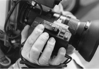
FIGURE 8.9
Traditionally designed TV zoom lenses have a hand grip like this one with a rocker-style zoom control, a button labeled RET to see return video from the deck (either from confidence heads or on playback), a switch to select auto/manual/remote control for the iris, and a button to set camera exposure if the iris is in manual control.
The range of the zoom can vary greatly from one lens type to another. Old consumer camcorders had a 6:1 or 8:1 zoom ratio. If the widest focal length was 9 mm, then the longest was either 54 mm or 72 mm, respectively. The zoom ratios for professional lenses are more often 14:1 or as high as 22:1. Lenses are often referred to as a 14× or a 20v or whatever the multiplier is for the maximum focal length. Sometimes the multiplier is followed by the minimum focal length. The Canon HJ40x14B lens has a 40:1 zoom ratio, and a 14 mm minimum focal length. This tells us that the maximum focal length for that lens is 40 mm × 14 mm, or 560 mm. When the range extender (×2) is added, the maximum focal length doubles, yielding a focal length of 1120 mm. Professional lenses with even higher focal length ratios are made, but these may require extra support brackets to attach to the camera. At such extreme focal lengths, it becomes very hard to maintain a steady picture on a lightweight camera even on a typical tripod, but especially when handheld or on the shoulder.
The widest focal length available on a zoom lens is about 4.5 mm, which is considered an ultra-wide-angle lens, but this lens does not have a large zoom ratio. Most professional wide-angle lens zoom ratios are about 10:1. Shooting with a wide-angle lens allows the videographer more control over the focus of the background and minimizes shakiness on handheld shots. Consumer and prosumer camcorders have lenses with greatly enhanced zoom ratios compared to older cameras. A ratio of 400:1 is not uncommon. Most of this high ratio is not accomplished by the lens itself but done electronically by digitally magnifying the picture in the camera. Most of these camcorders have built-in image-stabilizing devices to remove the annoying shake from the shots, but these devices generally only help a little. The best advice here is to avoid using the digital zoom feature. Besides the inevitable camera shake, the image is often grainy and not of professional quality.
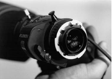
FIGURE 8.10
The lever on the back of this lens can be moved for the v1 (normal) position to the v2 (double) position.
A common feature on TV zoom lenses is the 2× range extender. This small device, which is part of the last elements at the rear of the lens, has a lever that can be moved to a 2 position; this drops an optical system into the light path, effectively doubling the focal length at which the lens is set. (See Figure 8.10.) It should be noted that this extender is somewhat fragile and expensive to repair, so treat the lever for the 2× range extender very carefully.
The zoom can continue to be used with the extender in place, but all focal lengths will be doubled. In effect, a lens that ranges from 10 mm to 100 mm would become a 20 mm to 200 mm lens with the extender in place. In the highly competitive news business, this added range to the lens is an absolute must. It is less important for field production, because the 2× range extender slightly degrades the quality of light passing through it. Whenever the 2× range extender is engaged, the amount of light passing though it is reduced by about one-half (the equivalent of losing one f-stop) and the sharpness of the image is sometimes reduced by a noticeable amount. This makes the extender of limited use in low-light situations. If the highest technical quality is required, use of the 2× range extender is not recommended; it should be considered only if it would allow you to get a shot that cannot be missed.
A minor drawback of zoom lenses is that they lose some light at the very end of their focal length range. For example, the Canon HJ40x14B zoom lens has a maximum relative aperture of f2.8 at 14 mm to 307 mm, but at 560 mm the maximum aperture is only f5.1. In low-light situations, this sudden darkening of the picture at the very end of the zoom can be noticeable. Therefore, for high-quality work, it is best not to use a zoom at the end of its range.
When the lens is zoomed all the way in, it is nearly impossible to get a steady picture. Any small movement of the camera will be greatly exaggerated by the long focal length; this makes steady telephoto shooting off the shoulder next to impossible. Today, many image stabilizers are available to take the shake out. Most modern home camcorders have similar devices built into them. One drawback to their use is the difficulty in panning (moving the camera left or right) or tilting (moving the camera up or down). These types of actions must be done slowly, or the motion control device overcompensates for the movement. Nevertheless, image stabilizers can produce spectacular results compared to ordinary zoom lenses.
LIGHT QUALITY CONTROL
The elements of the lens combine to make the sharpest image possible with the smallest loss of brightness at the focal plane where the image will be recorded onto a light-sensitive medium. Because lenses are sealed units, the operator has no control over how well the lens works inside. The last layer of quality that the manufacturer puts on the lens is a special coating on the glass. This coating helps with color reproduction and aids in correcting many minor flaws in the ability of the glass to transmit a sharp image. Special care must be taken when cleaning a lens so as not to harm this coating.
The best way to insure against damage to the front element of your lens is to always keep a clear filter or a UV (ultraviolet) haze filter on the lens. Many TV stations and production houses have a rule that a camera never leaves the building without one of these filters on the lens. Neither filter has any noticeable effect on the picture quality or the amount of light transmission; they merely serve to protect the front element from scratches, dirt, and other problems that could cause costly repairs or lower the quality of the lens.
One of the most common problems in maintaining picture quality is glare on the lens from light sources. At certain angles to a light source, light rays reflect off the front element, causing a glare across the lens surface. This glare reduces the contrast of the picture as well as its sharpness. Just as our hands often function as a sunshade for our eyes when we look in the general direction of the sun or any bright light, the camera lens needs the same protection to work at its optimum. The sunshade or hood that comes with the lens is an absolute must to prevent direct light from striking the front element. As the light source comes closer and closer to the camera’s field of view, it becomes increasingly difficult to protect the lens. Glare is actually the worst when the light is just outside the shot. You may find yourself using your hand to shade the light from the lens.
Once the light source is in the shot itself, there is little that can be done. When a light is in the shot, the glare is reduced, but other effects called flares (circular patterns of reflections in the lens) can be just as objectionable if not used in an artistic fashion. (See Figure 8.11.)

FIGURE 8.11
Lens flare from the sun.
ACCESSORIES
Many attachments are available to enhance lens performance. Many videographers like to take shots at closer than the shortest focal length allowed by their standard lens. Although changing to a wide-angle zoom lens is probably the best way to get a wider angle shot, it is also time consuming to change the lens, not to mention the inconvenience and expense of having a second lens available. A wide-angle retrozoom is another set of optical elements that can be mounted on the front of most professional zoom lenses. This attachment works like the 2× extender, only it decreases the focal length by multiplying it by around 0.8. This would make an 8 mm lens work like a 6.4 mm lens, but still allow zooming and focusing as normal. The other way to get a quick wide-angle shot is to attach a single-element wide-angle adapter. This curved lens either clamps or screws onto the front element of your normal zoom lens, much like a filter. The drawback here is that the picture can be focused only with the macrofocusing device, thus preventing the use of the zoom: the lens becomes a fixed focal length rather than a variable focal length lens.
There are teleconverters that look and work like retrozooms to make objects even larger. Teleconverters multiply the image size (commonly by about 2.8 times the image size). One drawback of both the retrozoom and the teleconverter is the added weight on the camera and lens itself. This can put added stress on the camera body at the point where the lens is attached.
Close-up lenses or diopters are single-element attachments that reduce the minimum focus distance of the lens. They also reduce the maximum focus distance so the lens can only be focused on objects close to the camera. Diopters come in different strengths, such as 2, 3, and so on. A strong diopter on a good lens will allow a camera to zoom in to the mint date on a dime so that it fills the entire picture. One drawback to diopters is that they require more light than a typical shot. A diopter will somewhat degrade the sharpness of a lens in high light levels but will greatly reduce the sharpness in low light with the lens iris wide open.
FILTERS
The clear glass and UV filters mentioned earlier are just two of the many types of filters available for a video camera’s lens. Most lenses have a threaded lip on the front element onto which a round filter or filter adapter can be screwed. Common diameters for video lenses range from 49 mm to 77 mm, although filter size may vary from one type of lens to another. Some lenses have no threads on the front element and require an adapting ring that clamps to the outside of the lens barrel. Most filters are threaded on both sides so that they can be stacked or combined with other attachments. Generally, no more than two filters can be used at one time without the filter edges showing in the corners of the picture. This is called vignetting and may also be caused by other factors, such as a poorly aligned lens. Many videographers leave the clear filter on the lens and add any other filters on top of it to make sure that the front element stays protected at all times.
Two other types of filter mounts are available for professional use: the round nonthreaded filters and the film-style square filters, such as the 2 × 2 inch, 4 × 4 inch, and the 6 × 6 inch. These filters require special adapters, which are made for every lens. With the larger unthreaded filters, it may be necessary to obtain a larger sunshade for the lens to avoid glare problems. The square filters are generally used with a matte box. (See Figure 8.12.) A matte box is a rectangular, tapered box that looks like a bellows and attaches to the front of the lens in such a way that the lens can be focused without rotating the matte box.
A series of slots at the back of the box permits the use of up to three square filters. These filter slots may be rotated independently of the lens to orient the filter as desired. (See the following discussion of star and graduated filters.) The rest of the box acts as a sunshade for the filters. The matte box is the most versatile and effective system of using filters with the lens, although it may be too cumbersome for most ENG work and some EFP shooting where weight and maneuverability are important considerations.
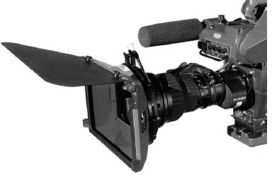
FIGURE 8.12
This simple matte box attaches directly to the front of the lens. It has two slots for 4×4 filters and has a “French flag” fixed to the front for added light flare protection.
Filters fall into three broad categories:
• Color enhancement
• Diffusion
• Special effects
Color enhancement filters can be used to change the perceived color of light used in a particular shot. This type of use is generally unnecessary because of the white balance circuit in the video camera, but they can be used to achieve very controlled, known artistic results.
Diffusion filters reduce the sharpness and/or contrast of the picture. They are often used to give a film look to the video or to soften skin-tone detail.
Special effects filters do everything from creating multiple images to split-screen fields of focus. Many of the effects created by these filters can also be done electronically in postproduction. Some of the new cameras can create these effects internally. It is a good idea to shoot a scene calling for filters at least once without filters, so that the producer or editor has the choice of using or not using the effect. Today, since advance editing systems are common, the need to use filters in the field has been greatly reduced. Many of the same effects can be done more easily in the computer without permanently changing the original image.
The following is a partial list of the more popular filters used in TV work. Most are used for EFP shooting or for feature stories in ENG. They are not recommended for general news use. Most of these filters come in different degrees of effect, rated from 1 to 5. A number 1 filter has only a slight effect, and a number 5 has the maximum effect.
Sepia Effect Filter This filter gives the scene a warm brown tone, similar to that of old photographs from the turn of the century. It can be used to imply a look back in time.
Enhancing or Warming Filter This filter creates a warm look by selectively improving the saturation of reds and oranges, with little effect on other colors. It is used to bring out better skin tones on light-complexioned subjects and give dark-skinned subjects a deeper, richer color. It is also good for the fall color shots of autumn.
Polarizing Filter This filter reduces glare and reflections on surfaces, such as glass or water, in the picture, while saturating colors and darkening in the blue of the sky. The polarizing filter is made to turn in its housing to achieve the correct angle to the reflections. As you turn the polarizer, watch the effect in the viewfinder to find the optimum orientation. It can make white clouds really stand out from the blue sky or take away annoying reflections from car windows.
Fog Effect Filter This filter creates the look of real fog in the scene. The effect is most noticeable in overexposed areas of the picture or around light sources in the shot. It can add a dreamlike quality to scenes or give atmosphere to interior scenes. (See Figure 8.13.)
Contrast Control Filter This filter lowers the contrast in the picture and mutes the colors. It lightens black areas and reduces the density of shadows so that more detail can be seen in the shadows without affecting the white areas of the picture. It is a good filter for scenes where shadows are particularly dark, and can help give video a film look.
Double-Fog Effect Filter This filter combines a soft fog with a heavy low-contrast effect that allows a sharper image than fog alone. It is particularly good to reduce the effects of overexposed windows in interior shots without adding a dense fog look to the picture.

FIGURE 8.13
These before and after shots show the effect of a fog filter that adds a fog effect and lowers contrast.
Diffusion Effect Filter This filter uses a slight ripple effect in the filter glass to reduce the sharpness of the picture without creating a foglike effect. It is often used to hide skin blemishes or wrinkles from the camera and looks good in backlit situations. It also causes a halo effect around light sources in the shot.
Softnet Filter This filter uses a net material between laminated glass to create a soft diffusion without the halation, or blurring, of highlights in the shot. The net comes in several colors, allowing multiple effects from one filter: black net leaves the dark areas dark; white net lowers the contrast as it diffuses; red net warms the colors of the scene; skin-tone net enhances skin color.
Dot Filter Instead of a net to cause the diffusion in the picture, this filter glass is covered by thousands of dots in varying sizes (similar to a paint sprayer mist). It comes in white, black, and skin tone. The filter is similar in effect to the net filters, but without the slight star effect on highlights.
Star Filter This filter has engraved lines that form a grid on the glass surface. The grid causes highlights, such as the sun, candles, and headlights, to appear starlike. The grid comes in different sizes from 1 mm to 4 mm spacing; a 1 mm grid has the longest rays and a 4 mm grid the shortest. Star filters also come in varying numbers of points; stars with 4, 6, 8, or 12 points can be created. These filters can give a glamorous quality to pictures with highlights in them, making them sparkle or helping reduce the sharpness of light sources (by using a 12-point 4 mm star) without affecting anything else in the picture. They are also free-spinning within their housings so the points of the star can be rotated to any angle.
Split-Field-Effect Filter This filter is basically a close-up lens cut in two. It allows you to have a close object in the bottom half of the picture and a faraway object in the top half of the picture, all in sharp focus. The one-half close-up lens is a fixed-focus element; this means that the lens must be focused first on the background and then the foreground object, or the camera must be moved in or out until that object is also in focus. This filter creates the ultimate depth-of-field lens, where everything from just in front of the lens to infinity is in focus.
Graduated Filter This filter contains the effect only in half the filter, while creating a smooth transition from that effect to clear near the middle of the filter. Graduated filters come as sepias, corals, oranges, and neutral densities. They are generally used over the sky portion of the picture to change the color of the sky without changing the color of subjects on the ground. They can create the look of a sunset sky without turning the ground pink too. The neutral-density filter can be used to gain an even exposure on the sky as well as the ground on overcast days. The filters work best in a matte box setup, where they can be positioned at just the right place in the frame without adjusting the shot.
A problem of some filters with nets and dots is that the diffusion material can sometimes be visible in the picture. This can easily happen when the lens is wide and at maximum aperture. The net or screen can be faintly visible across the entire picture. A good way to avoid this is to get filters that fit behind the lens. For video cameras, this would mean having them in the filter wheel of the camera. If this is not possible, it may limit the use of some filters to smaller apertures or longer focal lengths so that they will not be seen.
DIGITAL EFFECTS
Most consumer and prosumer cameras come with the ability to perform digital effects that were previously only available through the use of a special effects generator (SEG).
Compared to older cameras, newer video cameras seem like computers with the ability to capture video as well. New video cameras can take an image captured by the camera and process it in a number of ways. Some examples of digital effects common in video cameras are:
• Negative image: The color and brightness of an image are reversed (e.g., light to dark).
• Monochrome: Color is removed from the picture to yield a black-and-white image.
• Sepia: The image has all color removed except for the sepia (brownish) color, which gives the illusion of old footage or an old movie.
• Solarization: The image is intensified and brightened to make it appear as if it is an illustration.
• Mosaic: A tiled effect is derived from the original image.
• Keying: Parts of a frame can be replaced with parts of other frames (e.g., a person inside a studio can be made to appear as if the person is outside or at some other location).
• Still shots: Many consumer video cameras have the ability to take still pictures and combine them with video footage.
Although these effects are handy when they are available in the camera, and can make home videos more exciting, most professionals wait for the digital effects to be added in postproduction. If you add effects to the original footage as it is shot, you will not be able to go back to the footage and use it in normal mode. Special or digital effects are not used when gathering footage for ENG use. As with many automatic features available on video cameras, digital effects might be best left in the off position, unless there is a compelling reason to use a particular effect. Digital effects can call attention to themselves, detracting from good videography and distracting the viewer. Again, it is probably best to make decisions about digital effects after the original footage is shot, when time can be spent viewing the footage and deciding which effects should be added during editing.
Interchangeable Lenses
Most cameras on the market are designed for use with specific lenses. A lens for a Sony camera cannot be put on a Canon camera unless it is modified at the factory. Some models of cameras may share the same lens specifications, but they are the exceptions. Each camera manufacturer has a different design for the way a lens works with its internal focus plane. And every camera must be shaded to any lens (i.e., adjusted to the light characteristics of the lens) that is being used on it to achieve the optimum quality.
Care and Cleaning of Lenses
Dirt is the great enemy of lenses, and it does not take much to get a lens dirty. In addition to the huge amount of dust in the air, there is always the chance that something will come in contact with the lens and smudge it, such as your hand or fingers. For the lens to work at its optimum, it must be free of all dirt and smudges. Loose dirt or dust can be blown or brushed away with the proper tools, but not wiped away. Touching the lens with a dry cloth or tissue may actually grind the dirt into the glass. For loose dirt, a soft photo brush and an air blower can be used. Simple squeeze-style blowers or air-in-a-can can be purchased at any photo store.
Do not, however, blow air from your mouth. If the squeeze-style or other type of blower does not clean the lens, switch to a liquid cleaner. Always try to use a cleaner made to be used on high-quality glass. Lenses, and even some filters, can be very expensive. A deep scratch or other blemish can require an equally expensive trip to the factory for regrinding, recoating, or replacement. Most stores that sell cameras also sell lens-cleaning solutions along with tissues to wipe the lens clean. A homemade solution of a few drops of dishwashing soap and distilled water works as well as some commercial products. A very clean, soft, lint-free cloth can also be used instead of the photo tissues. There are also products on the market that have premoistened towelettes in individual packets specifically formulated for cleaning lenses.
No matter what you use, the method should be the same. Never use more fluid than you need and never grind the pickup material (e.g., a tissue) into the lens. Always use a circular motion and try not to go over the same part of the lens more than once if you can help it. A good cleaner used sparingly will do the job, and any excess will evaporate quickly. Never use plain water; it has too many mineral deposits in it and does not evaporate quickly enough.
Keep a cap on the lens at all times when the camera is not in use, such as when it is in transit, in storage, or in any hazardous environment (a desert or beach, or in windy conditions). Often the dirt on your lens will not be visible in the viewfinder. Visually inspect the cleanliness of the lens often. The time when dirt really stands out is when there is any glare on the lens or a highlight, such as the sun, in the shot. While a little glare and the sun may be part of the shot, any dirt on the lens will stand out and result in an embarrassingly amateurish shot. The time to find out that you have a dirty lens is not in the middle of a shot where you pan past the sun. It might have been your only chance to get that shot.
Modern professional TV lenses are made to work in harsh environments, but they do need routine cleaning. The rotating barrels of the focus, zoom, and iris all must be kept clean. Wipe the lens free of any dust and dirt as often as possible. Use a compressed air blower to get in the small places, possibly with the help of a soft brush such as a toothbrush. Never use water to clean the lens. Never use any cleaner that has oil in it. All the moving parts of the lens and servos are on sealed bearings and need no further lubrication. If they are stiff to use, they are dirty, not in need of an oiling. Make sure the gears and teeth of the lens barrel are always clean and free of dirt and dust. Most lens units are considered waterproof, but are really just water resistant. If exposed to excessive dampness, they may short out, or dirt may collect in the condensation and foul the servos at a later time. If the lens does get a bad drenching, allow it to dry out completely by putting it in a sealed plastic bag with silica gel or another desiccant (a substance that absorbs moisture).
Check the tightness of all the accessible screws on the lens (including the back of the lens) as well as the lens control unit on a weekly basis. Like most TV equipment, any repair work or extensive servicing should be done by experienced people. If you wish to do more than basic care, have someone with more experience show you the right way to do it. The final word on lens care is to know the lens’ factory service center nearest you. Most offer overnight service or even loaner lenses; they can certainly help you over the phone with small problems. Expensive professional lenses often are sent for a factory overhaul every two years.
VIDEO CAMERAS
A current-model portable video camera barely resembles the huge, heavy studio camera of TV’s early years, because of the numerous design changes made over the years. But the color video camera of the earlier days of TV had to perform the same basic functions as today’s cameras: light filtering; the separation of white light into red, blue, and green; image sensing; and signal processing. Today’s cameras are simply smaller, lighter, and more accurate.
Recently, a new style of video camera has reached both the professional and amateur video market. These DSLRs resemble the old 35 mm single-lens reflex film camera bodies. They are capable of shooting very high-quality still photos, but they also shoot high-quality HD video and are rapidly being developed for the ENG and EFP market. DSLR cameras are smaller and lighter than professional video camcorders and allow users to choose from many interchangeable lenses. DSLR cameras have larger image sensors (close in size to traditional film formats).
Another recent innovation is a video camera that is designed to replace traditional film cameras for feature film shooting. One example is the Red camera, a product of the Red Digital Cinema Camera Company, first released in 2007. This camera can record video with resolutions up to 4096 horizontal × 2304 vertical pixels (similar in size to 35 mm film), which can be recorded directly to a flash memory or hard drive storage.
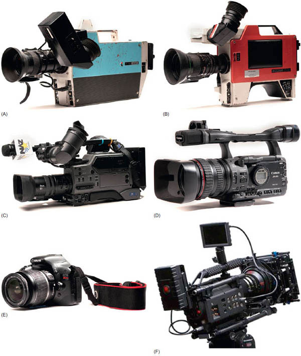
FIGURE 8.14
(A) This Ikegami ITC 350 camera was popular in the very early days of portable video. Note that the camera control switches are on the front panel. (B) This slightly newer Ikegami camera had a built-in shoulder mount and switches on the side of the camera. Both A and B used vacuum pickup tubes, which resulted in a “hump” at the top to accommodate one of the pickup tubes. (C) A more recent camera used for ENG has solid-state image sensors, built-in VCR, side controls, and a built-in shoulder cushion. (D) This small and lightweight Canon camera can shoot in either SD or HD and stores images on a mini-DV videotape. (E) This camera, a DSLR, is small, light, and is designed very differently from traditional video cameras. (F) This high-resolution RED digital camera is designed to replace traditional film cameras.
Camera Basics
We have taken the light that makes up a real image, traced its progression though the lens, and seen how the lens may manipulate it. It is now time to transform that image into a form we can use.
In a film camera, this would be as simple as having a light-sensitive material on a celluloid backing exposed to the image. The camera would simply be a device that moves and positions the film. For a video camera, recording the image is a more involved and complicated process. The inside of a TV camera is filled with computer chips, circuit boards, wiring, and at least a dozen places to make adjustments. Since making a change in any one of the adjustments causes a change in the remaining unadjusted areas of the camera, the proper equipment and the proper training are required of anyone who touches anything on the inside of the camera. Unless an experienced maintenance person has shown you how to make adjustments inside your camera, do not try it.
In the new world of digital cameras, making adjustments is considerably easier. A digital camera is software driven. In older cameras, adjustments were made by turning tiny screws. In today’s digital cameras, they are made by calling up menus in the viewfinder screen and using buttons to raise or lower selected values. (See Figure 8.15.) If you don’t like the way your changes look, you can always go back to the default settings and start over. Anyone can adjust the camera parameters and be able to reset the camera to its normal setup.
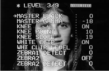
FIGURE 8.15
This is one page of a setup menu on a digital video camera. Buttons or other controls on the camera allow you to scroll through the pages and the individual menu items to change their values.
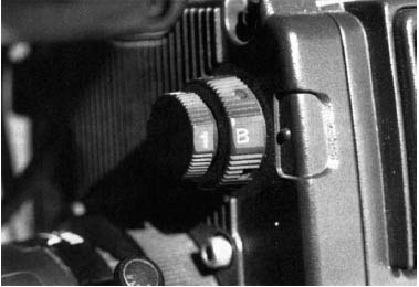
FIGURE 8.16
The front of this professional camera has two filter wheels. Here, they are set in the “1” and “B” combination.
FILTER WHEEL
As it comes from the lens, the first thing an image passes through in a network-quality camera is a filter wheel. This wheel (sometimes two wheels) contains typical photographic filters, just like those on the front of a film camera lens. (See Figure 8.16.) Normally, there are three types of filters in the wheel: clear, color correction, and light reduction. The electronics of a camera are similar to a roll of film: film has a specific speed or level of sensitivity to light, known as the ASA (from the American Standards Association), and is designed for a specific color of light.
All video cameras are designed to work their best with light at 3,200°K (Kelvin), the color temperature of typical TV lights. Cameras produced for today’s consumer or prosumer market adjust to varying color temperatures by changing a menu setting. In many professional cameras, adjusting to varying color temperatures requires changing the setting on the filter wheel(s).
Shooting a scene lit by TV lights is done with the filter wheel dialed to the clear (3,200°K or indoors) position. If the shoot is outdoors in sunlight, then the filter wheel is turned to a daylight or 5,600°K position. This filter is nothing more than an orange-colored filter designed to convert daylight color temperatures to that of tungsten (TV lights).
Video cameras can be balanced to any light temperature, but assume it is operating at its factory-designed optimum (or preset) of 3,200°K. As the amount of sunlight increases, a video camera can increase shutter speeds to regulate the amount of light it receives if the range of the iris has been exceeded. This usually has an adverse effect on any movement in the picture, however. The most effective way for a video camera to handle high brightness levels is to simply select a neutral-density filter (ND) on the filter wheel. In single–filter wheel cameras, NDs are usually combined with a daylight color-correction filter.
The standard one-wheel camera has four positions on its wheel:
• Clear (3,200°K): Used for interior shoots, or exterior at night.
• Daylight (5,600°K): Used outdoors in moderate amounts of sunlight intensity or in shaded areas.
• Daylight + ¼ ND: Used for open sunlit areas on clear days.
• Daylight + ⅛ ND: Used for very bright daylight scenes, such as a sunny day at the beach or the ski slopes.
A ¼ ND allows 25 percent of the light to pass through it without affecting it in any other way. A ⅛ ND allows 12.5 percent of the light to pass through. Although each camera model has different nomenclature or different combinations in its filter wheel, they all operate on the basic principles stated earlier. These filters allow a camera to shoot in any typical lighting condition.
PRISM
The light forming the image passes through a prism after going through the filter wheel. Unlike most consumer and low-end industrial cameras, which have only one pickup device, a professional camera will split the beam of light into its three primary additive colors for TV, which are red, blue, and green. These are not the primary subtractive colors for mixing colors; red, yellow, and blue are the colors for mixing paint and should not be equated to the primary additive colors (for mixing light) in any way. The way a TV camera arrives at all the colors of the rainbow is considerably different from the way an artist does on a canvas or even from the way a filmmaker does in making a color print. The camera prism delivers a very pure blue, green, and red picture to three targets or light-sensitive surfaces. These three colors can be recombined later to represent the true colors of the object being photographed. It is the intensity of each TV primary color that determines the true color when the information is recombined into a video picture.
CHARGE-COUPLED DEVICES
In the 1980s, cameras were designed to use charged-coupled devices, or CCDs, from the older methods of using light-sensitive tubes. The CCDs became known simply as chips. After about 1990, camera manufacturers stopped making cameras with tubes, because the chip technology far surpassed tubes. Many problems that were inherent in tubes, such as smear, lag, and burn-in, were eliminated by the use of chips.
Most chips are rated by the number of pixels each chip has. Each pixel is like a grain of emulsion on a film; the greater the number of them present, the sharper the image. The more pixels present on a chip, the more sensitive the chip is to light. Newer cameras can almost see in the dark. They are capable of making good pictures in no more light than that of a single candle. This is something a tube camera could never do.
Two kinds of image sensors are common in video cameras: CCDs and CMOSs (complementary metal-oxide semiconductors). The technology for both of these image sensors changes rapidly, but as of 2012, CCDs are more expensive and less susceptible to noise in the picture. CMOSs are cheaper to manufacture and have led to lower prices in digital cameras, but they are more susceptible to noise in the picture and are less light sensitive than CCDs. CCDs however, require more battery power for proper operation than CMOSs.
Advances in CMOS technology have resulted in new video cameras that can produce a film-quality image. Sony intends for cameras like these to be appropriate for independent filmmakers, where budgets and crew size are much smaller than Hollywood feature films. The Sony F3 and similar cameras have high sensitivity and allow a shallow depth of field to give a cinematic look. The camera allows interchangeable lenses (single focal length) and records onto an S × S card, a recording format that is both faster and is physically smaller than its predecessors.
VIDEO SIGNAL
Electronic impulses from the chips are sent on to the rest of the camera, called the processor. Much of the camera’s insides make up the video processing unit of the camera. This complex series of boards and circuits shapes the video image into its many parts, mainly chroma (color) and luminance (brightness). Before that information leaves the camera, it can be recombined into one composite signal or left separate in its component state to be recombined later. Component video carries the chroma and the luminance or brightness signal in separate wires. (See Figure 8.17.)
FIELDS AND FRAMES
The images of the video signal are relayed in a similar manner to that of film. Each video image is just like a frame from motion picture film. Video is recorded at a rate of 30 frames per second, however, instead of 24 frames like the movies. Each video frame is made up of two fields, sometimes called odd and even. These fields are essentially half pictures that are combined through a process called interlacing. Video shot at 60i means that 60 fields of video are shot per second and combined to make 30 frames of video per second.
Progressive scanning shows each frame of video in sequence rather than alternating odd and even fields. Old CRT-type displays were capable of showing interlaced video only, while newer digital monitors and TV sets are designed to show progressive scanning, but are capable of showing interlaced scanning video.
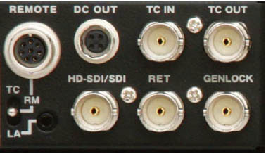
FIGURE 8.17
This view of the side of a digital camera shows a variety of inputs and outputs for time code (TC) and Genlock. The connector labeled HDSDI/ SDI is capable of carrying HD video and four channels of audio and is similar to the BNC connector used for many years.
NTSC, PAL, AND SECAM
Whether a video signal is component or composite, it is based on a reference system. In the United States the reference system used from the late 1940s until 2009 was NTSC, named after the National Television Systems Committee. Only a few other countries used the NTSC system, most notably Canada, Mexico, and Japan. NTSC had 525 lines of resolution and scanned at 59.85 fields (29.97 frames) per second. Common practice for discussing frame speed is to round off to 30 frames per second. One drawback to the NTSC system was that it allowed the viewer at home to adjust the color on their TV set. This led NTSC to be jokingly referred to as “Never Twice the Same Color.” Having no guarantee that the viewer’s set is properly adjusted can mean a great deal of loss for the artistry of video.
The other two reference systems in the world were the PAL and SECAM standards. Phase Alternation Line (PAL) was developed by Germany, England, and Holland in 1966. PAL had 625 lines of resolution and scanned at 50 fields (25 frames) per second, but the system did not have color controls on the TV receivers like NTSC. Consequently, PAL had less color distortion than NTSC, but because of the slower scan rate, many NTSC viewers saw PAL pictures as flickering too much. In 1962, France introduced the Sequentiel Couleur À Memoire (SECAM) system, which was later adopted by the Soviet Union and several other European countries. SECAM had 625 scanning lines at 50 fields (25 frames) per second, like PAL.
These three systems were not compatible with each other. A special device was necessary to translate one system to another when making copies of programs.
DIGITAL VIDEO
The system adopted by the United States, Canada, Mexico, South Korea, and other countries is referred to as ATSC, for the Advanced Television Systems Committee that helped develop it. Digital video’s aspect ratio is 16:9, wider than the NTSC 4:3. The system is capable of producing 1,080 lines of resolution—far more video information than the 525 (480 displayable) lines in NTSC. The 1,080 resolution is only one version of digital television, which will also support SDTV, standard-definition television (480 or 576 lines), or EDTV, enhanced-definition television (720 lines).
In digital video, images and sound are captured using digital sampling technology, delivering a movie-quality experience, multicasting, and interactive capabilities. All full power television stations in the United States switched from analog to digital broadcasting on June 12, 2009. The FCC made this decision to improve the technical quality of broadcast television because digital video:
• Is free of ghosts and snow
• Allows multicasting (several channels of programs instead of just one)
• Can be compressed and stored easily
• Allows multiple generations of copies without noticeable decline in quality
Digital video also differs from analog video in the way the picture is shown on the screen. Digital video can use progressive scanning, while analog video only used interlaced scanning. In progressive scanning, the image is displayed on a screen by scanning each line (or row of pixels) in a sequential order rather than an alternate order, as is done with interlaced scanning. Progressive scanning scans the image lines (or pixel rows) in numerical order (1,2,3) down the screen from top to bottom, rather than in an alternate order (lines or rows 1,3,5, etc. followed by lines or rows 2,4,6). Progressively scanning the image onto a screen every 60th of a second, rather than using “interlacing” alternate lines every 30th of a second, produces a smoother, more exact image on the screen that is perfectly suited for viewing fine details, such as text. Progressive scanning is also less susceptible to image flicker, which is common with interlaced scanning.
Digital Video Broadcasting-Terrestrial or DVB-T is the system adopted in many European countries for digital broadcast television systems.
CAMERA FUNCTIONS
On the outside of every professional-quality camera are the operational controls. These switches and buttons are the primary means of controlling the electronics inside the camera. Each model and each camera manufacturer can have widely varying controls and placement of controls on the camera body. (See Figure 8.18.) Although cameras generally don’t have many switches, just one of those switches being in the wrong position can affect the quality of the video or even prevent the camera from operating.
Power Switch There is always a main power switch on the camera that sends energy to all parts of the camera or camcorder. Another switch on the camera may control the power to the record device and also acts as a power saver to the camera itself. This switch can be a three-position switch: Standby, Save On, and On. Standby is used when you do not need to operate the camera but want to start up the camera suddenly. A trickle current from the power source keeps the circuits warm and allows the camera to be ready to shoot in just a couple of seconds when it is turned on from the standby position. Save On gives you a picture in the viewfinder, but if the camcorder has a VCR, it prevents the VCR’s tape servo motors from coming up to speed, thus saving power. If you try to record when the camera is in this mode, it will take a couple of seconds for the VCR servo to come up to speed before the recording can begin. In a news situation, this is clearly a disadvantage, but if you are spending quite a lot of time lining up or waiting for a shot, this function lets you work with the camera picture without running down the camcorder battery until you need to record. But more important, if the servo is left running without recording, you are needlessly wearing down the video record heads and the drums of the tape machine and running an increased risk of damaging the tape itself. Digital recorders do not need this function because very little power is needed to keep the DTE recorder or flash memory recorder ready to record. The On position is when everything is up and ready for instantaneous recording as soon as the button is pushed.
Camera/Bars Switch This switch makes the output of the camera either the picture or the color bar generator contained within the camera.
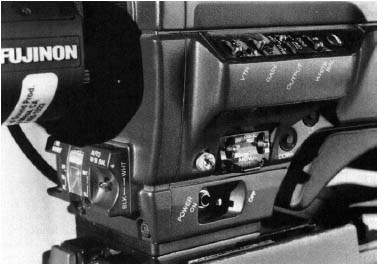
FIGURE 8.18
All the camera function switches are located on the lower front and side of this professional camera.
Gain Switch Most cameras offer the user three choices of gain in the sensitivity of the chips. Gain, which is measured in decibels (dBs), is usually left at zero or normal for most shooting but can be raised as high as 48. To raise the level of exposure if the lens is wide open, you can shift the gain switch by one position. Under extreme low light, you can go to the last position of the gain switch. Each position increases the sensitivity of the chips by the amount labeled on the switches or on some cameras by the amount you have predetermined. Gain increases also increase the picture noise (graininess). Although some newer cameras can boost the gain up to 48 dB, even an 18-dB picture gain is not considered to be of professional quality unless it is a news shot under terrible conditions. Even a 9-dB gain can be objectionable in some news and almost all EFP situations. Use gain only when you cannot get a picture without it.
White Balance Button To allow the camera to work under any type of light, each professional camera has a white balance circuit. By showing the camera something white (zooming in on a white card, wall, or paper) and pressing a button or flipping a switch, the camera sets the reference volts on each chip to make a white picture with that color of light. An indicator in the viewfinder tells the operator when the white balance is done (usually in two or three seconds, or less). Some cameras also show you what the color temperature is after the white balance procedure has been completed.
Some cameras have a black balance switch to set the black reference in the camera. This is done automatically in most cameras, but heat can affect the black balance. If your camera has a black balance, you should use it every time you white balance, or any time the atmospheric (hot/cold) temperature changes even if the light does not. A good camera should white balance under most colors of light when the proper filter wheel or setting is selected. Again, in consumer and prosumer cameras, the white balance function can be automatic. The automatic setting is great for saving time and avoiding mistakes, but it relinquishes creative control to the computer in the camera and can lead to subjects being shot in the wrong color.
White Balance Channels Many professional cameras have three channels of white balance circuits from which to choose. The first two are normally called A and B. They both work the same way and allow you to balance for two scenes. If a shot requires you to follow a subject from a sunlit area to a room lit with only incandescent light, you can set the white balance on A for daylight and on B for incandescent. As you follow the subject from one room to the other, only a quick flip of the switch is needed to maintain the proper colors. The third position is Preset. This setting puts the camera in its factory-preset white balance of 3,200°K, the TV lights’ normal color temperature. The camera now acts like a film camera with a constant color reference (i.e., it is the same as using a selected film stock); any correction for color temperature has to be done by means of filters in or on the camera or on the lights themselves.
Shutter Selection Video cameras have variable shutter speeds, much like still cameras. The normal shutter speed of a video camera (controllable by an electronic shutter setting accessible through the setup menu) is ![]() of a second. Speeds of
of a second. Speeds of ![]() ,
, ![]() , and
, and ![]() of a second are usually available. These additional shutter speeds allow the camera to achieve certain special effects or let the operator shoot at low f-stops in bright light, but they are not useful in most situations. The most common use is when using an isolated sports camera. The faster shutter speeds allow for brilliantly clear and sharp slow-motion pictures and freeze frames of fast-moving objects. The trouble is that when these pictures are played at normal speed, they appear to stutter or show a strobe effect on the screen. You should only use the faster shutter speeds for shots to be played in slow motion or frozen, or for shots with little movement.
of a second are usually available. These additional shutter speeds allow the camera to achieve certain special effects or let the operator shoot at low f-stops in bright light, but they are not useful in most situations. The most common use is when using an isolated sports camera. The faster shutter speeds allow for brilliantly clear and sharp slow-motion pictures and freeze frames of fast-moving objects. The trouble is that when these pictures are played at normal speed, they appear to stutter or show a strobe effect on the screen. You should only use the faster shutter speeds for shots to be played in slow motion or frozen, or for shots with little movement.
CLEAR SCAN
You may have noticed that when computer screens are shown on video, they often have an annoying flicker or rolling, as though the horizontal hold is broken. Computer monitors do not scan their screen at the same rate as normal television monitors (59.85 Hz). They can scan at rates both higher and lower than that of video. Many professional cameras can change their own scan rates to match any computer monitor by use of a selection switch, usually as part of the shutter switch, called clear scan. This option allows the camera to show very clear, flicker-free computer screens. Matching rates to some monitors with really low scan rates can leave the camera’s ability to shoot moving subjects greatly reduced, and any movement by the camera, such as a pan, will result in blurred pictures.
MONITORING THE PICTURE
Up to this point we have only discussed the inner workings of the camera and the means of controlling those functions. Now it is time to see the results of what the camera is doing, starting with what the camera sees and analyzing the quality of the video output.
Viewfinder In some early video cameras, the viewfinder was simply a glass window with some crosshairs in it. The operator never even looked through the lens. Today’s cameras have high-resolution video mini-monitors as viewfinders. When looking through the viewfinder, you will see exactly what the recorder or any output destination of the camera sees because the picture appears after it has been processed. Note that most viewfinders on professional video cameras are black and white. The viewfinder has brightness and contrast controls that need to be set at proper levels. The contrast control should be turned up all the way, and the picture quality should be adjusted by the brightness control only. A good picture should show whites as white and any deep shadows as a rich black.
The viewfinder also shows information in addition to the video. Some information is contained in the picture itself, such as the zebra striping. The zebra bars that appear over parts of the picture are a graphic display of the exposure level. Most cameras come from the factory with the zebra bars that can be set at levels between 70 percent video, or 70 IREs (Institute of Radio Engineers’ standard measure), and 100 percent, or100 IREs, of video. This means that any portion of the picture with an exposure of 70 units or above, as measured on a waveform monitor, will have these stripes. This measure, 70 units, corresponds to the proper exposure of skin-tone highlights on a subject with a light complexion or the proper exposure of a white piece of paper. If a person’s face is the part of the picture that needs proper exposure, then the zebra bars should appear over the brightest highlights on the face, usually the cheeks and center of the forehead. (See Figure 8.19.)
Many videographers prefer that skin tones be more in the 55- to 65-unit range to avoid that video look, and they back off the iris (reduce the exposure) just until the zebra bars are removed from a face. Some videographers prefer to set the zebra pattern at 100 units to better see overexposed portions of the picture, especially when people are not in the shot. Anything above 100 IRE will lose all detail and be seen as a white glow. Zebra bars can be set at any level by an experienced videographer or service person, and many cameras can show two different sets of zebras at the same time; for example, one a standard crosshatch at 70 units, and the other a square mosaic set at 100 units.
Other warning lights or indicators show low battery power, end of tape/memory, low-light levels, filter selection, and shutter speed.

FIGURE 8.19
Zebra bars appear on the face of the subject as seen through the LCD viewfinder of the camera. These bars are set at 70 IREs, and their appearance on the highlight areas indicates proper exposure.
LCD Viewer Consumer and prosumer cameras now come standard with a fold-out liquid crystal display (LCD) viewer. This display, although somewhat low in resolution, provides the videographers with a good color picture of the shots as they are recorded. The LCD displays are thin and consume a small amount of power compared to old cathode ray tube (CRT) monitors. When shooting with the LCD display in use, the viewfinder is often disabled. This may cause problems for some videographers who choose not to get too close to the camera because of their vision, because the image may appear fuzzy. This alters the shooting style a bit, especially for those experienced shooters who are used to direct contact with the viewfinder. Instead of pressing an eye to the rubber cup to see into the viewfinder, the videographer views the image in the LCD at a distance of 6 inches or more. LCD viewers will show all the same information that can be seen through the viewfinder.
Color Bars The color bars are the most common reference point in video work. Most professional cameras have a switch that turns on a color bar generator and feeds the color bars to the camera output. This internal color bar system is essential to track down any problems in the video system, because it is a known reference. If the color bars do not look right, nothing else in the video will either.
ASSOCIATED TEST EQUIPMENT
Waveform Monitor A waveform monitor is needed to make adjustments on the electronics of a camera. (See Figure 8.20.) In the past, only camera maintenance people used this device, but the data it provides are needed for any high-quality work with cameras, recorders, digital devices, microwave or satellite transmitters, or time-base correctors. Many professional camcorders now have this function built into the camera, allowing the videographer to view the waveform. The waveform monitor is the window to the inner parts of the video signal. Problems with the video signal can be found by analyzing the different information available from the waveform monitor. A videographer who wishes to truly master a video camera should learn to read and use the waveform monitor.
Connecting a camera to a monitor and experimenting with exposure should give some information on how a video signal works and how to recognize problems in the camera.
Vectorscope The vectorscope also checks the color or chroma of the TV signal. (See Figure 8.21.) If reds in the picture do not look right, this scope can identify whether it is the operator’s eye, the TV set, or the camera that is wrong. The waveform monitor and vectorscope are the two most important means of analyzing the quality of your video signal. Some video cameras now come with built-in waveform and vectorscope information.
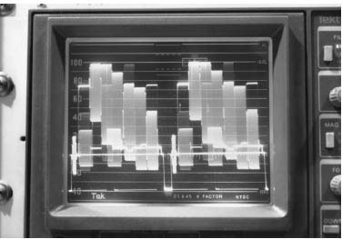
FIGURE 8.20
The waveform monitor shows what color bars look like when everything is working properly. This picture looks at both fields of one frame of video and shows both chroma and luminance.
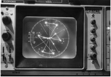
FIGURE 8.21
This vectorscope shows how color bars are represented when the video signal is optimum.
Color TV Monitor The most common, but technically weakest, form of monitoring the video picture is the color TV monitor. It is good for showing composition to others such as the director, producer, or reporter. Unless the monitor has been carefully set up and adjusted, and viewing conditions are optimal (e.g., no glares or high room light), any other information such as true color reproduction or even exposure cannot be judged from the picture on the screen. The viewfinder and the waveform and vector monitors are the most accurate indicators.
A small color monitor (5–9 inches diagonal screen size) is also good for the cameraperson to use as a viewfinder on lengthy shoots when the camera is in a fixed place on a tripod. The strain on the eyes, neck, and back can be greatly reduced by having a conveniently placed monitor (to line up and maintain the framing).
Maintenance To maintain your camera, protect it from shock and keep it clean. There is virtually nothing inside a camera that the typical operator can repair or adjust. Take good care of the camera and notify qualified maintenance personnel if there is a problem. It is the operator’s job to keep the outside of the camera in the best possible shape. All screws, especially those holding the side panels in place, must be checked for tightness on a regular basis. Protect the camera from the elements as well as from bumps, jolts, and drops. Although most cameras are somewhat water resistant, none of them are waterproof. A rain jacket, a plastic protector shaped to fit the camera and keep moisture out, should be taken on the shoot if you are shooting outdoors.
Troubleshooting You must be able to tell when something is not right with your camera. When your car makes unusual noises, you bring it in for a mechanic to check it out. When your video camera starts giving substandard pictures or strange colors, have a technician test it. Sometimes a thorough checking by the camera operator can isolate problems to certain areas of the camera, which can lead to a very simple operator-capable fix. A switch in the wrong position is the most common error. Know where all switches should be set, and check them first in case of trouble. Check your power source. Put up color bars and see how they look. If the bars look good, then you know the problem is not in the output of the camera, but in the input before the image gets to the video processor section of the camera. Unfortunately, most internal problems cannot be fixed in the field. Identify a good maintenance person or factory service center if you do not have an in-house repair facility or when you are out of town.
VIDEO RECORDERS
Cameras designed for portable video (excluding webcams or surveillance cameras) have some type of video recording device as part of the design. While it is easy to see the unit as one piece of equipment, it is necessary to think of each component as separate. Cameras are combined with digital videocassette (DVCPRO, XDCAM, or mini-DV), DVD, hard drive, or flash memory storage.
THE FORMAT WARS
The following discussion about formats and videotape sizes is thankfully becoming less relevant than it used to be. The history of formats described next has been frustrating to videographers because as the technology has changed, so has the associated equipment. As formats come and go, expensive equipment becomes obsolete. Currently, devices are being marketed that will convert HD video to the needed format. Channels and networks have varying requirements for resolution and frame rate, so the introduction of converters that can be mounted on the camera and allow video to be recorded in the format required by the client are a welcome technological innovation.
NEW VIDEO FORMATS
Recent changes in the way video is recorded have both helped and hindered portable video shooters. In the picture below, you can see a digital cinema style camera, the Sony F3 which has a 4/3 image sensor for excellent video reproduction. The device on the right, behind the camera, is a digital video recorder, the AJA Ki Pro Mini Compact Field Recorder that records video in the correct format for editing on Final Cut Pro. The device records directly onto a Compact Flash card.
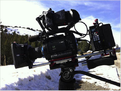
In the early days of videotape, the standard was a two-inch reel-to-reel tape developed by Ampex. The recorder was as big as a desk, and editing was accomplished by using a magnifying glass and a razor blade. It was never practical for field use. A one-inch tape format (known as type C) was developed, and it became the studio standard for many years. It had very good resolution and allowed special effects like slow motion without distortion. This one-inch type C format had very limited use in the field. Although portable one-inch decks were made, they were just barely portable and certainly not dockable with a camera. They were usually mounted on a cart and could not be subjected to any movement, such as being carried, while recording.
Because of the size of the tape, the amount of storage space it required, and the cost of the tape, other, more practical formats were developed.
From its introduction in 1982 until about 10 years ago, the Sony Betacam dominated the professional world of videotape for portable recording. But as video slowly converted to digital, a host of new formats arrived on the scene. It is likely that more formats (and recording media) will be introduced in the near future. If this process of advancing technology follows the computer world, then any prediction today as to what the future will bring will be wrong. No one knows the future. The only thing you can say for certain is that the future is digital. The following is a brief rundown of the formats in use, past and present.
Older Formats: Hi8, S-VHS, and ¾-Inch SP
The biggest revolution in the video world came when broadcast-quality equipment became available to the average consumer. By the mid-1980s, the average citizen could produce a TV program that was equal to the technical quality of broadcast quality. The Hi8 and Super-VHS (S-VHS) formats had the minimum 425 lines of resolution necessary to be considered broadcast quality. In the early 1990s, network news turned to these formats during the Persian Gulf War because of their small size, light weight, and relatively high quality. Parts of one episode of a popular TV sitcom, Growing Pains (1985–1992), were shot on Hi8 without any noticeable dip in quality. Both the Hi8 and S-VHS formats came in models that featured all the options of a professional format in a slightly larger package than the regular consumer models, and both made dockable decks that could go on camera heads designed to be used with higher-quality formats.
The ¾-inch U-Matic format was the standard of the portable video world for more than a decade and was the first easy-to-use format that allowed nonbroadcast users the ability to shoot and edit in a format that was relatively inexpensive. The quality approached broadcast quality when the format was enhanced to U-Matic SP using metal tape. However, this format was quickly replaced in the professional world when higher-quality formats (e.g., Betacam) emerged. U-matic machines are no longer being manufactured. Because of the vast libraries of ¾-inch tapes in the world, playback machines in U-matic format stayed around for a long time, but the machines are scarce now because both the tapes and the machines are bulky and the quality cannot compete with newer formats.
Standard Analog Videocassette Formats: Beta SP and MII
In 1982, Sony developed a ½-inch videocassette format for broadcast use from their Betamax consumer format. The new format was introduced as part of a one-piece camera recorder unit they called a Betacam. The term went on to mean the Beta format for professional use, as opposed to home-use Beta tapes. Many people still mistakenly refer to any professional camcorder as a Betacam, whether it is made by Sony or not. The original Betacam format is no longer made and was replaced by Beta SP. Like ¾-inch SP, this format enabled the use of the older format tapes but greatly improved the quality of the video when metal particle tape was used.
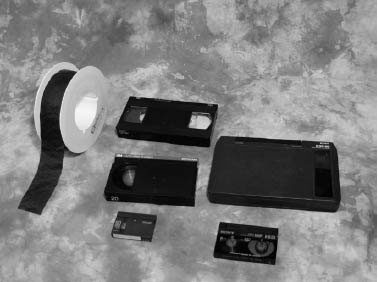
FIGURE 8.22
Video tape sizes: upper left, 2-inch reel-to-reel; upper center, ½-inch VHS/S-VHS; center, ½-inch Betacam; lower center, mini-DV; lower right, Hi8.
Another ½-inch tape, the M format, was introduced by Panasonic in the mid-1980s, about the same time as Betacam. It was an offshoot of VHS but never developed a professional following. In 1987, the MII format was introduced to compete with Beta SP. MII also made use of ½-inch metal particle tape, but used a cassette shell unique to its format, unlike the Beta tapes, which used the original Betamax cassette shell. Blank Betamax tapes purchased at the local discount store worked in a professional Beta machine. The M formats, which never found a wide following, are no longer manufactured. Panasonic replaced them with digital formats.
Digital Formats: D Series, Digital Betacam, Betacam SX, DV, DVCAM, DVCPRO, and Digital S
While digital tape is the only tape format still in use for shooting, no one standard has come to the forefront to dominate the industry. As you’ll see in the descriptions of the different formats that follow, confusion is the best way to describe the situation. As we will keep mentioning in this book, it is unlikely that any of these formats will survive. Just like the MII format, rising technologies will overtake the weaker, less popular forms. But for now, the following is a thumbnail sketch of what’s out there today.
Many postproduction (editing) facilities have been using digital recorders for some time to create the edit master. Earlier ¾-inch cassettes and the later models with ½-inch cassette tape systems were made by both Sony and Panasonic and designated by a “D-x” notation (e.g., D-1, D-2, and so on); these replaced the one-inch tape recorders. These machines were used occasionally in studios, and not taken into the field.
STANDARD ½-INCH FORMATS
In 1993 Sony introduced the Digital Betacam format, using a discrete cosine transform (DCT) recording technique referred to as the ITU-R 601, with a 2.34:1 compression ratio and a recording data rate of 127.76 Mb/s (megabytes per second). The resulting files are similar to JPEG files in the computer world. This format is often referred to as Digi-Beta, and it is commonly in use for broadcast and cable/satellite program work. One version of this format came as part of a one-piece all-digital camcorder, the BVW-D700. In late 1996, Sony also introduced another digital format, Betacam SX, which used 10-bit MPEG-2 digital encoding with a 4:2:2 sampling rate, 10:1 compression format, and an 18 Mb/s data record rate. MPEG-2 is the digital method used in most digital editing and all digital transmission. The 4:2:2 sampling means that for every four luminance samples taken, two red samples and two blue samples are also taken. This format was particularly interesting to news departments, because the signal can be transmitted via microwave at two times normal speed, thus reducing transmission time. Sony also introduced yet another format called MPEG IMX as an edit format, but not for field use. Also, JVC introduced Digital S, also known as D-9, which was based on their S-VHS system and has an 8-bit 4:2:2 sampling rate in a dual-DV recording format (two DV chipset processors used in tandem) and a 50 Mb/s data rate.
THE 6.35 MM TAPE FORMATS
In the 1990s, the consumer and lower-end professional or industrial market transformed to a digital format called DV, using a smaller tape width of 6.35 mm. DV refers to a specific method of recording a digital signal on the tape, similar to JPEG files but differing from other files like MPEG-2 and DCT, a format developed by Ampex. All DV formats use an 8-bit 4:1:1 sampling rate in which only one red and one blue sample are taken for every four units of luminance, a compression of 5:1, and a data recording rate of 25 Mb/s.
The camera and lens will always outperform the recording device, regardless of the format. There is no question that the DV-formatted camcorders look better than their Hi8 and S-VHS predecessors. DV, made by both Sony and Panasonic, became the format of choice for consumers, prosumers, and budget-minded professionals. The development of this format—especially mini-DV cassettes—led to the design of camcorders so small they fit into a shirt pocket, and has brought professional quality to almost any user for a reasonable price.
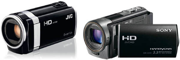
FIGURE 8.23
These camcorders are typical consumer-style cameras. Both feature optical and digital zooms and record images on a flash card.
Sony introduced its DVCAM version of DV to appeal to the industrial or prosumer market. The major difference between DVCAM and Standard DV is a larger spacing of the recording tracks (called track pitch), which requires the tape to run at a faster speed. This change is a benefit in editing, because it enables more accurate edits and fewer audio problems.
Panasonic’s upgraded version of DV is the DVCPRO. Its real difference from DV is the double tape speed, which has a better tolerance of tape drop out. Unlike the larger professional formats, DV tapes can be recorded and played in different manufacturers’ machines. Sony’s DV and DVCAM can be played in Panasonic’s DV and DVCPRO decks, and vice versa. For all practical purposes, there is no quality difference among any of these four formats. DVCAM and DVCPRO are better formats for professionals, because of the increased editing capabilities and other added features of their respective machines, but the actual quality of the recording is the same.
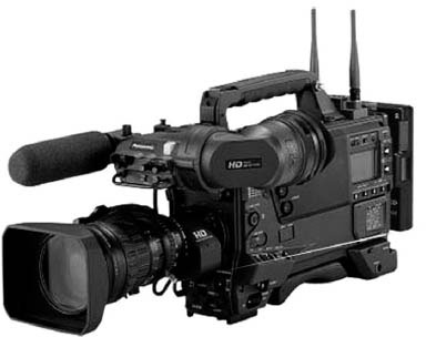
FIGURE 8.24
This Panasonic AJ-HDX900 camcorder brings HD recording within the reach of many video professionals.
Panasonic took the DVCPRO to a new level with their AJ-HDX900 DVCPRO HD camcorder, first introduced in 2006. This camera was designed to provide global content providers (digital cinematography, cable and television program production) with a moderately priced camcorder (under $30,000) that can produce HD images in any of 11 video formats.
If you are confused about formats, don’t worry—most people, even professionals, are also confused. The marketplace for format choices is very confusing. The one thing to carry away from this discussion of formats is their compatibility (or noncompatibility). Close attention must be paid as to where and how the recorded material is to be used. How many points of transfer or translation is that tape going to have to go through? In the transfer/editing/transmission/storage process, the different machines or systems handling the signal can go from 8-bit to 10-bit, DV to MPEG-2, 25 Mb/s to 50 Mb/s, and so on and vice versa, with the resulting picture ending up worse than an old analog picture.
It would be a disservice to you to try to predict which if any of the current formats will survive or dominate in their current form. The acceptance of digital format acquisition methods at the professional level has slowed somewhat because of the previously stated confusion and the mismatching formats. It is likely, however, that we will continue see videotape replaced with several types of random-access media during the next few years. Only then will video be truly digital, free of the limitations presented by the moving parts and mylar-based tape inherent with the use of videotape. The only thing that is certain is that many of the functions of the recording device will remain the same.
Digital Video Recorders
After years of dealing with a multitude of clumsy and sometimes annoying videotape formats, a huge change is occurring. Three types of digital “tapeless” recorders are available for professional, prosumer, and consumer use. Direct to DVD, DTE or direct to edit, and flash card recording are commonplace. Many camcorders, especially at the consumer level, record video directly to a mini-DVD disc. DTE recorders can record video onto a small hard drive or flash memory card and are similar in size and shape to an iPod. Flash memory recorders can record video onto flash cards similar to those found in digital still cameras.
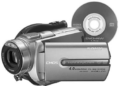
FIGURE 8.25
This Sony camcorder records directly to a DVD.
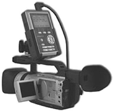
FIGURE 8.26
Small digital recorders like this one mount easily on a video camera and replace bulky videotape recorders. After recording video in the field, this recorder can be directly connected to a nonlinear editing system using FireWire. These devices are also known as DTE recorders.
DVD Recorders DVD recorders are common in many camcorders. A DVD recorder allows digital recording, random access, and easy editing. These camcorders are consumer level and are not good enough for professional work. Hitachi hit the market first in 2000 with the DZ MV100, which featured MPEG-2 compression, basic editing tools, and easy navigation for both playback and record. The recording is made onto a mini-DVD disc (8 cm in diameter, about 3 inches) and could be played back on any DVD machine. One of the criticisms aimed at these camcorders has been the lack of a FireWire output to allow easy input to a nonlinear editor, but this connectivity issue has recently been addressed by the manufacturers. DVD camcorders are now considered “low end” with many models available for less than $300.
DTE DTE digital video recorders are small outboard devices that record onto a hard drive or flash memory and resemble an iPod. Video is recorded onto and from the recorder by using a FireWire cable that can pass audio, video, time code, and other control information. These recorders are designed to facilitate direct to edit by allowing the easy transfer of video to a computer equipped for nonlinear editing. Recording on this type of device allows the user to begin editing without capturing, file transferring, or converting the video files. The device acts as an external hard drive (which it is) and can be accessed easily from the computer.
Flash Memory Many camcorders on the market now have the ability to record directly to a solid-state memory card that is inserted directly into the camcorder. This storage medium is neither tape nor disc. One version that has been on the market since 2007 is the Panasonic P2 card, which is really four flash memory cards combined into one larger card. Many other camcorders and DSLR cameras store video on an SD (secure digital) or CF (compact flash) card. The advantage of this storage method is that it has no moving parts and is not sensitive to extreme temperature, vibration, or shock. The manufacturers claim that the cards are rewriteable up to 100,000 times. Since flash memory cards do not use tape, they are not susceptible to tape dropout, making flash memory cards a clean edit source. Shots can be thought of as computer files and can be transferred and organized into folders, making editing easier.
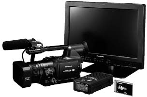
FIGURE 8.27
This Panasonic was one of the first affordable camcorders that recorded on a flash memory card (a P2 card, lower right), which could be inserted directly into a laptop for editing.
Time Code
One of the most important pieces of information in video recording is the time code (TC). Similar to edge numbers in film, the time code allows each frame of the video to be numbered. When a tape is played back, scenes or shots can be referred to and located by their time code number. In older professional analog machines, time code was recorded like an additional channel of audio on the videotape. It had a separate track and its own space on the tape. This type of encoding was called linear time code (LTC). On newer tape formats, there is also a form of time code recorded in the picture portion of the video signal. The numerical information is added to the vertical interval space left as the tracing beam shuts off to return to the top of the picture. This channel of time code is simply called vertical interval time code (VITC).
User bits are stored in yet another portion of the video signal. They can store characters of the alphabet as well as numbers. Whatever is entered into the user-bit channel will be recorded within every frame of video, just like time code. Once set, user bits do not advance or change as the recording takes place. Each frame has the same information. That makes user bits a good way to label video shots. The “reel” number, camera ID number, operator’s name, initials, date, or unit number can be placed in this channel to aid in cataloging later. The limit, however, is eight characters.
On machines that allow it, one of the more popular uses for vertical interval time code is as a clock. While linear time code is usually set on Record Run so the numbers only advance when the tape does, VITC can be set on Free Run so the numbers continue to advance no matter what the VCR is doing. The VITC can be set in sync with any clock, such as a wristwatch. Many news videographers set the VITC in sync with their reporter’s watch. In this way, a reporter can take time code notes using the time of day while the videographer is shooting. During a long interview, soundbites can be noted easily without looking at the recorder. Later in editing, the reporters can simply have the editor switch the playback machine to VITC and search quickly for the sound or shots referred to in their notes. This can save valuable minutes when editing under deadline pressure.
Professional camcorders and decks always have TC in and out ports (see Figure 8.17). On multicamera shoots, one camera or deck can be designated as the master TC source and feed the other units—a process called slaving—so all the tapes will have the same TC while recording. This makes the editing process much easier by allowing the editor to sync up the same scene shot from different cameras and intercut them as if the scene were being edited live at the location.
One disadvantage of the newer DV formats at the prosumer level is the inability to customize time code. Although most recorders have TC, it cannot be set by the user and has no separate in and out ports. Each tape put into the machine starts at 00:00:00, and the machines don’t allow multiple recorders to be synchronized to the same time code during recording. But the good news is that all DV formats have time code, and it can be read by almost all nonlinear editing programs.
Troubleshooting
The advent of tapeless recorders has simplified recording in the field. Although these recorders have fewer moving parts because they have no tape drive mechanism, they still do have some problems.

FIGURE 8.28
A typical cable with the BNC connector. In analog video this cable carried either a video or audio signal. In digital video, this cable carries a video signal with up to four audio channels.
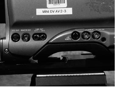
FIGURE 8.29
Some typical input/output connections on a professional camcorder.
The most common reason a recorder or camera will not work is also the simplest: no power. It is often easy to tell when there is no power present, but a drained battery can sometimes work some functions but not others. Check the battery first. In tape decks, the most common problem is the tape itself: Is the record tab in place? (If not, the machine will not record.) Is the tape being threaded? (If not, it may not be seated properly in the tape carriage.) Is the tape rewound? Once these things are checked out, the problem may be in the circuits that control the mechanics, sometimes called the machine’s logic. Shutting off the power to the deck for a minute or two may clear the logic circuits and allow them to reset. The last area of possible trouble is the mechanics of the deck. A dirty pinch roller can cause the tape not to thread properly. Most problems such as these, however, require a trip to the maintenance department. In the digital tapeless recorders, memory must be managed to provide enough space for recording.
You should know the position of every switch on the deck or recorder for every function you wish to use. You may never use some of the switches because of the type of work you do, but if they are in the wrong position for some reason, they may prevent the correct operation of the machine. Study the manuals for your equipment carefully. It is not uncommon to have just the playback function of a deck fail, so in certain circumstances, you may want to play the tape back on another machine, just to be sure. Very little field repair work can be done on a video recorder, although one easy fix is to clean the clogged video heads. They can be easily unclogged without a trip to the shop, even if a head-cleaning tape is not available on location. A new, unused tape can be played or fast-forwarded in the clogged deck. The rougher surface on the new tape can often break the clog loose.
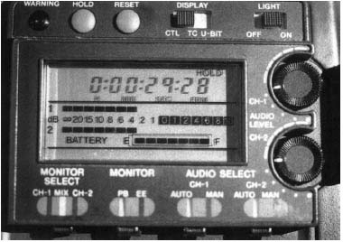
FIGURE 8.30
This display panel on a professional camcorder shows the audio level at −4 dB.
BATTERIES
In recent years camcorders have been available with much lower power requirements than in the past. Today, new technologies are changing the once-heavy batteries into fairly light, compact units. Like the technology used in cell phone batteries, many battery styles are going to nickel metal halide (NiMH) versions. Their power-to-battery-weight ratio makes them a good choice for field use. Additionally, lithium ion technology is also being used in battery production, replacing a Ni-Cad-type battery weighing several pounds with one that weighs several ounces, yet gives the same or even more power.
The battery’s power output must match the power requirements of the equipment to which it is hooked. The most popular battery for network-level camcorders is the clip-on brick battery, a generic name for any cube-style battery. The 18.2- or 14.4-volt capacity of these batteries gives them the reserve power to operate the equipment at its rated volts (12 volts) for the maximum amount of time without harming them.
Battery capacity is rated by ampere hours (Ah). The typical brick battery has a rating of 4 Ah; that is, it can deliver one amp of power for four hours. Your camcorder’s manual will tell its power consumption and how many watts the camcorder uses, say, 18 W. Amps are watts divided by volts. In this case, 18 watts ÷12 volts = 1.5 amps; this means that a 4-Ah battery should run the camcorder for a little longer than 2.5 hours (1.5 amps = 2.7 hours). Of course, the exact time will vary depending on the age of the battery and the operating conditions. Older batteries tend to “fade” and have less capacity than newer batteries. Also, batteries that are operated in extreme cold or hot conditions may not work as efficiently as those operated in more moderate temperatures.
Various types and sizes of packaging are generally used for the batteries used in today’s video productions.
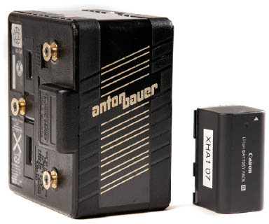
FIGURE 8.31
The “brick” battery on the left was the most commonly used battery style in professional video work for many years. Newer, smaller cameras can now use lithium ion batteries that are smaller and lighter, like the one on the right.
Proper Care
Batteries are very susceptible to temperature, both hot and cold. The ideal temperature for a battery is about 75°F, but as temperatures drop below freezing or go above 100°F, the ability of the battery to deliver power starts to fall off rather quickly. In very hot climates, or when batteries are left in the car for long periods of time, a cooler with a no-leak ice pack is a good way to ensure fresh batteries. The reverse is true for very cold weather: keep the batteries as warm as possible. Temperature also comes into play when recharging the battery. Never try to recharge a frozen or a blazing hot battery. Always allow the battery to reach a normal temperature before putting it through the rigors of charging. When using lithium ion batteries, it is wise to charge them the night before a shoot.
TRIPODS AND CAMERA-MOUNTING DEVICES
Professional portable cameras are designed so they can be used on the operator’s shoulder for handheld photography. Although this is essential, it is not the optimum way to use the equipment. Most professional uses of portable cameras and camcorders involve a tripod mount. The tripod raises the production values of photography more than any other element except lighting. Nothing says “amateur” more than handheld shaky shots.
Fluid Heads
Most professional tripod heads involve a combination spring/fluid mechanism for giving pans and tilts a smooth motion. The fluid acts as a dampening agent to resist movement so that the camera does not simply jerk up and down or to the side. There are two adjustments for the fluid (one for tilt and one for pan) that can make the resistance as heavy or as light as the operator likes. There are also locks for the pan and tilt to keep the camera in one place without drifting. A third function on the head is the counterbalance, which adjusts the internal springs to the exact weight of the camera.
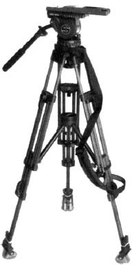
FIGURE 8.32
This standard professional tripod and head has two-stage legs, a midlevel spreader, and a shoulder strap for easy carrying.
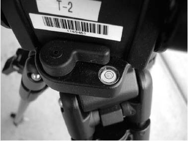
FIGURE 8.33
Fluid heads like this model help the camera operator get smooth pans and tilts. The bubble indicates when the head of the tripod is level.
To make a fluid head work, the camera’s center of gravity must be perfectly balanced on the head. To do this, the head itself must be leveled (using the plumb-bubble bull’s-eye found on the head), the pan and tilt locks must be off, and the pan and tilt friction must be set at the lightest setting. There should be an adjustment on the quick-release plate to slide the camera back and forth to get its center of gravity over the center of the head so the camera stays level without touching it. Lock the sliding plate in this position. A good fluid head should permit you to tilt the camera forward and back with minimal friction dialed into the tilt function, and you should be able to take your hand off the camera at any angle and have the camera stay in that position without drifting. If it does drift, it means the spring portion—the counterbalance—of the head is not adjusted properly. The head must be rated for the weight of the camera. If the camera is too heavy or too light for the head, all the functions of the head will be of little value. Trying different levels of friction can help you find the point where the camera can make very smooth movements with little effort.
Tripod Legs
The days of the wooden tripod or sticks are long gone. Most tripods today are made of alloys, graphite, aluminum, or carbon glass, and are very lightweight. The lightness is a great asset for the news crews, but weight can be helpful to stabilize the camera, particularly on windy days. Never trust a tripod to hold your camera up in a strong wind or in any situation where things are likely to bump into it. Lightweight tripods are made to help the operator, not to take the responsibility for holding the camera. If you walk away from the camera, make sure that the camera cannot fall, or take it off the tripod and set it on the ground until you return. Anchor weights or sandbags to hold the tripod firmly in place are always worth using.
The best tripods have a two-stage leg deployment that can vary from a height of about 26 inches up to around 6 feet. The length of each leg can be set separately so the tripod can be used on uneven surfaces with minimum leveling at the head. Most leg designs make use of the spreader, or spider, to keep the legs from sliding out from under the camera on slick floors. These spreaders have an adjustable span to bring the legs in closer, spread them further apart, or be removed entirely in difficult situations.
Dollies
A dolly is a movable device that allows you to mount the camera on it and shoot steady video while moving. The simplest form of a dolly is wheels on the tripod legs. While this type of dolly may be good for some basic moves, it is hard to control and almost impossible to steer once movement starts. Many dolly platforms are made to use a standard tripod attached to them. The most common dolly, a doorway dolly, accommodates any tripod but is small enough to fit through most doors. This dolly has large inflated tires that give a smooth ride over fairly flat surfaces. For uneven or rough surfaces, the tires can be replaced with special wheels that run along rails laid on the ground.
Common items can be used to make a dolly without much cost or hassle. The most popular is the wheelchair. While the operator sits in the chair with a shoulder-mounted camera, another person can easily roll the chair. Wheelchairs are good for minimizing shocks due to pavement irregularities, because their wheels are large. They are also handy because they can fold up and fit in the trunk of a car to get to the location. Another possibility is the typical grocery store cart. Industrial carts (like the ones you might use at Home Depot or Sam’s Club to move large purchases) can work well. Shooting from a slow-moving car can work for tracking shots, but don’t even think about shooting while driving unless you can operate the camera with a remote control. Shooting through a car window can be difficult because of reflections off the glass. Try not to touch any vibrating surface while shooting. Although it may seem like a good idea, avoid shooting from the back of a pickup truck. If the truck moves with any speed at all, the camera and the operator are at high risk. Just about anything with wheels can be made to work in certain situations; just consider safety in addition to aesthetics.
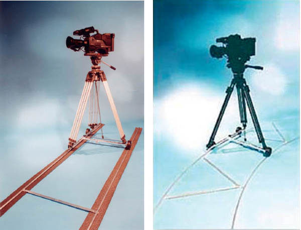
FIGURE 8.34
Two dollies commonly used for location shooting. These dollies can be easily disassembled and packed in a small carrying case.
Cranes and Booms
The crane shot is a favorite of the movie industry. The shot starts out high and wide as the camera slowly descends to eye level in the middle of the action. On a crane, the operator sits on a platform that is raised or lowered at the end of a long arm. A boom has the camera remotely mounted on an arm. All camera functions, such as pan, tilt, zoom, and focus, are done at the base of the boom arm. The smaller versions of these booms are very popular in video field production and can be operated by one person.
Cranes and booms can also add an incredible amount of production value to the shoot by moving the camera through a space where no person could go, such as sweeping over the heads of the crowd.
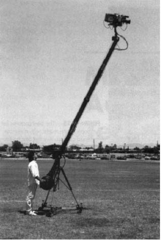
FIGURE 8.35
A video camera mounted on a boom.
Steadicam®
The Steadicam revolutionized the handheld camera. One of its first uses was for shooting the 1976 motion picture Rocky with a film camera. Subsequently, it has been used extensively with both film and video cameras. This complex system of counterbalanced arms is connected to a harness worn by the videographer, with the camera mounted at the end of the armature. Although it is rather strenuous to operate, the Steadicam combines many of the effects of the dolly and crane to achieve an incredibly stable picture, even with the operator running over obstacles or down stairs. In the professional model, the camera operator can view the picture on an LCD screen mounted near the bottom of the mount. A video screen mounted in the arm near the hand grip allows the operator of the Steadicam JR to see the picture from the camera, no matter which way the camera is pointed. A new, smaller version is made specifically for EFP. It is lighter and easier to use, but still takes a considerable amount of practice to learn. Many smaller and less expensive versions of this camera mounting system can be found for home or industrial use.
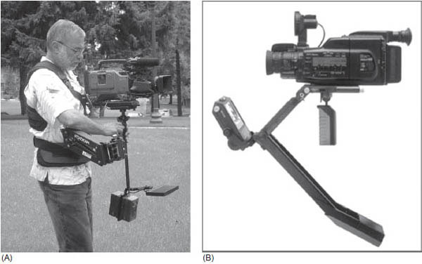
FIGURE 8.36
(A) The Steadicam Flyer model is a professional mount worn by the camera operator and can get great shots even when the camera operator is moving. (Courtesy of Alan Lifton; photo by Julie Bergman)
(B) The Steadicam JR is designed for consumer or prosumer cameras, and can be held by the camera operator.
Shoulder Mounts
The newer DSLR cameras are small and lightweight, but may produce shaky video when the shooting is handheld. Many manufacturers are creating shoulder mounts for these cameras for use when steady shots are desirable, but a tripod limits the camera movement.
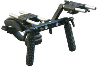
FIGURE 8.37
Shoulder mount for a DSLR camera.
Car Mounts
Shooting in or into moving cars can be very troublesome. If the camera must be mounted outside the car, a suction device with a camera attached grips the hood or door. This mount can provide some dramatic angles, but safety lines should always be used in case the suction doesn’t hold. Sets of bars and clamps that fit almost every car are also available; these allow a camera to be placed almost anywhere.
Aerial Mounts
Shooting from aircraft can be very limiting because of the air turbulence and the vibration of the engines. Even in a helicopter, the picture generally looks steady on wide shots only. As soon as the videographer zooms in, the viewer can see the chop of the ride. One commonly used mount for aerial photography is the Tyler Mount, which functions as a Steadicam in the air. Attached to the frame of the aircraft, this mount removes the vibrations and minor bumps of the ride and lets the camera produce a steady picture, even at long focal lengths. The aircraft must be approved for using it, but the Tyler Mount offers excellent aerial photography.
Several devices available today mount externally onto aircraft that contain the camera in a large spherical housing. The direction and zoom of the camera are controlled remotely by an operator from inside the craft. Freeway chase videos, which have become common news video, especially in large cities, were shot from helicopters using some form of external mounted camera stabilization system.
Special Mounts
Many types of mounts can be made with a little ingenuity. The key is making them strong enough to hold the camera and withstand other forces. If you can think of a place to put the camera, then someone can surely devise a way to get the camera there. (Remember, however, that anything attached to the outside of an aircraft would have to have FAA approval.) With the advent of small HD cameras (some with suction cup mounts like the GoPro Hero camera), it is possible to put a camera just about anywhere. A small camera can be placed at the end of an audio boom to get shots from odd places, such as holding the pole with the camera out of one moving car to shoot another car. You can move the camera from the wheels, up the side, over the hood, and then raise the camera to let the car speed on past under the camera.
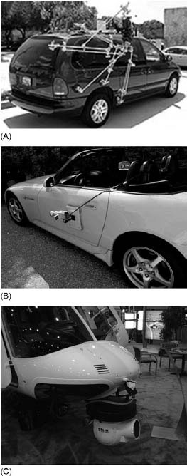
FIGURE 8.38
(A, B) The car mounts allows a camera to be mounted outside the vehicle to get shots of chase scenes and for shooting objects in front of the camera car. (C) The aerial mount on this helicopter allows a camera operator to control the camera from inside the helicopter. This particular camera and mount system is for an infrared camera, which will get usable images even when shot at night with almost no light on the subject.
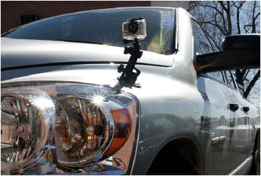
FIGURE 8.39
The HD GoPro camera has suction cup mounts and can be placed on helmets, race cars, or surfboards for great action shots.
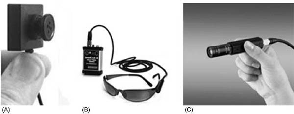
FIGURE 8.40
(A) A button camera, which can be worn as part of the camera operator’s clothing. (B) This camera shoots video from the frame of the sunglasses. (C) This camera is called a “lipstick camera” because of its size and shape. (Photos courtesy of Jones Cam, Elmo)
The key to mounting any camera is always safety—for the camera, the operator, and any members of the crew or public. Mounting a camera on a roller coaster might seem like a good idea, but only if you have taken into account the G-forces of the ride. Is the mount strong enough to withstand being whipped around at several times the force of gravity? It could be a life-threatening disaster to have the mount break and the camera sent flying in the middle of the ride. Safety first.
Miniature Cameras
One of the great benefits of the new DV-format cameras is their small size relative to their quality. Where at one time mounting a Betacam in a difficult situation would be time consuming and possibly dangerous, a small DV camera can be placed with ease and secured safely. Through the use of fiber optics with these small cameras, cameras can now be hidden on a person. No longer is a bag or briefcase necessary; the camera lens can be hidden in a pair of sunglasses and the recorder hidden in a jacket pocket. Many of the numerous poker shows on television use miniature cameras mounted within the customized arm rests of the poker table. These cameras give the audience a view of the players’ “hole” cards, which are dealt face down. Other applications include hidden camera shots during investigative reporting in ENG work.
SUMMARY
Creating professional-looking videos requires the videographer to know about the equipment. This chapter discussed the basic components needed for professional video production in the field using portable video equipment.
Video cameras have complex lens systems that are capable of collecting, magnifying, and controlling the light that goes through them. Lenses can be set wide to get a shot with a long distance from left to right or at telephoto to get a magnified shot that has a short distance from left to right. The amount of light that passes through the lens is controlled with the iris control. Some cameras have auto-iris controls, but these should only be used in special circumstances, because they restrict control over the light entering the camera in a way that may not be appropriate for the shot. Lenses can be adapted to special situations or yield special effects when fitted with a variety of filters added to the front of the lens.
Video cameras, at first equipped with vacuum pickup tubes, now have solid-state devices to change a light image into an electrical signal that can be processed in the camera and then sent to a recorder or monitor. Most consumer and prosumer cameras can perform a number of functions automatically, but professional cameras allow the camera operator to switch off these functions to allow manual control of the video being recorded. A recent innovation in video cameras is the digital single-lens reflex camera. This camera looks like a still-photo camera, but has excellent video recording capability.
Video recorders have changed from analog videocassette recorders to digital videocassette recorders, hard drive recorders (direct to edit), and flash memory recorders. The newer recorders are smaller and higher quality than the older analog versions. In addition, both DTE and flash memory recorders save time by allowing immediate editing after shooting. Video formats have changed from analog to digital, and there are numerous choices available. The use and care of batteries, tripods, and various camera mounts was also discussed in this chapter.