9
ENVIRONMENTAL MODELING
1. What Is Environmental Modeling?
The work of a game audio sound designer doesn’t stop with designing great sounds. Just as important is the ability to create a satisfying audio environment within which those sounds can live and thrive and provide the player with as much information as possible on their surroundings and happenings. Successful environmental modeling is also an important factor for immersion, by helping create a rich and consistent picture of the environment surrounding the gamer.
In Chapter two we outlined some of the ways that sound can provide us with many different cues that can assist the player with critical information on their surroundings. In this chapter we will look at the ways that we can create such environment for our sounds to live in and propagate and ultimately inform and immerse the player.
Calculating and recreating the exact acoustical properties of a space requires a significant amount of computational power, still exceeding the real time capabilities of most machines. Most game engines tend to take the more practical approach of giving us tools that allow us to approximate the acoustics of the worlds we aim to create and transport our players to, rather than simulating the exact acoustical properties of a space. Remember that as game designers our task is not to recreate reality but to create a convincing and engaging environment within which players may find themselves immersed, informed and entertained, serving both gameplay and storyline. In fact, in some cases recreating the actual properties of the space we are in might actually prove counterproductive. A space may require a long, very harsh sounding reverb, but that might make the mix difficult to listen to, and if dialog is present, it might become unintelligible. Over large distances emulating the speed of sound and therefore the delay between a visual cue (such as a lightning bolt) and the aural cue (thunder) might prove distracting rather than immersive, even if technically accurate. There are countless examples where in the context of a gaming experience reality is not the best option. Therefore, when it comes to environmental modeling, focus on the gameplay and narrative first and foremost and realism second. Once you’ve established a set of rules for your level, be consistent and stick to them. Changing the way a sound or environment behaves after it’s already been introduced will only serve to confuse the player and break immersion.
Environmental modeling can be tricky, especially with more complex levels, where the behavior of sound might be difficult to establish even for a veteran audio engineer. This chapter outlines some of the most important elements that the game developer ought to address. This is in no way intended to be a scientific approach but rather an artistic one. There is science to what we do, but as sound and game designers we are, at our core, artists.
1. Reverberation
Too often, Environmental Modeling in a game is summarized to a hastily applied reverberation plugin, often ill chosen. While reverberation alone is not the only aspect of creating a convincing audio environment, it is indeed a crucial cue and one that deserves our full attention. Reverberation provides the user with two main clues as to their surroundings: an impression of distance from the sounds happening in the space and a sense of the space itself, in terms of size and materials. A complete lack of reverberation will make it much harder for the player to properly estimate the distance of objects and will sound artificial. As previously seen, however, distance is not just a factor of reverberation; loss of high frequency content and perceived width of a sound also come into play.
Another common misconception is that reverberation is an indoors only phenomenon, which is of course untrue. Unless our game takes places in an anechoic chamber, any other environment will require the addition of reverberation.
a. Pre-Computed vs. Real Time Computation
Reverberation is a relatively costly process, and resources are always a concern when dealing with real time applications. There may be instances in which you might be able to ‘print’ or bounce audio files with reverb out of your DAW and import them in Unity that way, with rendered reverberation. This may be possible in a few cases, but generally speaking, reverb must be implemented in the level itself in order to sound convincing. Most reverb plugins tend to work in real time, computing reverb at each frame of the game, but some third-party software packages offer non real time solutions that can be quite convincing. Often, these software solutions will need to render a separate reverb map, similar to the way lighting is usually rendered in games. This process of rendering a separate reverb map prior to running the game is known as baking. We shall, however, focus on the solutions available within Unity at the moment of this writing.
b. Absorption Coefficients
Environmental modeling needs not be realistic. Ultimately, as with every aspect of the game, it is second to the narrative. Some reverberation processors, however, usually non real time ones, allow the user to match the materials used for the geometry’s surfaces used in the level to acoustical properties based on real life behavior. These values are usually based on tables used by acousticians, known as the absorption coefficients of various materials. Absorption coefficient tables provide us with a detailed way to understand how various kinds of materials absorb or reflect sounds at a wide range of frequencies. An absorption coefficient of 0 means that all sound was reflected and none absorbed, while a coefficient of 1 will mean that all sound was absorbed and none reflected.
Although Unity at the time of this writing does not natively support such a solution, (third party developers for Unity do provide such solutions) you might want to consult such tables, freely available online if you are unsure as to the reflective properties of various common materials or if you are looking for a reference point to start from.
c. Environmental Modeling With Reverberation in Unity
Unity’s reverberation algorithm allows us enough flexibility to model most situations we will come across in our work, although the way it breaks down parameters may appear confusing initially when coming from a music or audio production background. We will shine a light on these parameters and how to use them shortly, but first, let’s look at how Unity allows us to apply reverberation. Unity offers several ways to add reverberation to a scene:
- Via an audio reverb filter, which is applied as a component to an object with an audio source.
- Via a reverb zone, which is added to an area in a scene.
- Via an SFX reverb effect, which is added to a mixer group.
They differ slightly in terms of the options and the parameters they offer, based on how they are intended to be used, but their features are somewhat similar. The Unity reverberation model breaks the signal down between low and high frequencies, expressed in a range from −10,000 to 0. The model also allows independent control of early reflections and late reflections as well as the overall thickness or density of the reverb. This implementation makes it a practical algorithm to model indoors and outdoors spaces.
d. Unity’s Reverberation Parameters

Figure 9.1
A reverb zone component.
Next, let’s try to understand how some of these parameters may be used most effectively in the specific context of environmental modeling.
2. Best Practices for Environmental Modeling
a. Late vs. Early Reflections
Remember from Chapter five that early reflections are the collection of the first reflections to reach the listener’s ears, prior to the main bulk of the reflections, known as late reflections (the portion of the sound most people associate with the actual sound of reverberation). The early reflections are a good indicator of the room size and shape, as well as the position of the listener in the space. If you are trying to model a large room, such as a train station for instance, a longer pre-delay is appropriate. A small living room will benefit from short to very short pre-delay time. Dense urban environments also generally have strong early reflections due to the large number of reflective surfaces. The smaller the space, the shorter the pre-delay time for the early reflections. The closer to a reflective surface, the shorter the pre-delay as well. No matter how small the space, however, you should never leave the pre-delay time at a value of zero (which, sadly, a lot of reverb plugins tend to default to and users never change). One reason to never leave the pre-delay time set to zero milliseconds is that it is physically impossible for the early reflections to occur at exact same time as the dry signal, as sound travels fast but not that fast. Another reason is that not leaving any time between the dry signal and the early reflections will make your mix muddier than it needs to be. The human brain expects this short delay and uses it to make sense of the environment.
b. Reflections Level
The reflections level parameter controls the level or loudness of the early reflections. This parameter tends to be influenced mostly by the materials that the space is covered in, rather than the size. A room with highly reflective materials, such as tiles, marble or cement, will demand a higher value for this parameter than a room covered in more absorbent materials such as drapes. Adjust it accordingly. You can always refer to an acoustic chart of absorption coefficients for various materials if unsure when tackling a new scene, but your intuition might serve you just as well, and ultimately your ears should decide. Having strong early reflections might be accurate, but could sound distracting and make the mix too harsh or sound modulated. As always, do what you feel best serves the story.
c. Density and Diffusion
Unity allows control over two kinds of reverb thickness and color: the density and diffusion settings. This allows the user to shape the overall tone of the reverb. The diffusion setting controls the number of echoes or delays making up the reverberation. It is recommended to leave this setting at a rather high value for best results and a lusher sounding reverb. As you decrease the amount of echoes that make up the reverberation, you will make the reverb thinner, which means it will allow for more room in the mix for other elements, but, on the other hand, lowering the diffusion also tends to expose each individual reflection more to the listener and starts to decrease the overall perceived quality and fidelity. The diffusion setting is a bit more subtle and acts as a little bit as an overall tone or ‘color’ control. At higher settings the diffusion will yield a rather smooth and interesting sounding reverb. Below a certain point, however, reducing this setting too much will result in the sound of the reverb being a bit more neutral, perhaps even bland and will at lower settings impart a cartoonish ‘boingg’-like quality reminiscent of a bad spring. Use both these parameters to tune your reverb to the appropriate settings, but I do not recommend lowering either setting too much for best results.
d. High Frequencies vs. Low Frequencies
Most real-world materials generally are better at absorbing high frequencies than they are at absorbing low frequencies. For that reason, most real-world reverbs will have a faster rate of decay at high frequencies than lower ones. When high frequencies linger on, they generally sound harsh and can easily pollute a mix and make it sound unpleasant and harsh to listen to. The decay HF ratio allows the engineer to control how the high frequencies decay over time when compared to low frequencies. A value of 1 makes both high and low frequencies decay at the same rate, while a value below 1 will shorten the high frequencies’ decay time, and, inversely, a value over 1 will extend them. You may use this setting to help you model the various materials and their frequency absorption coefficients but also adjust the tone of the reverb itself. A room covered in heavy fabrics will absorb high frequencies faster than one covered in tiles. Use the decay HF ratio setting to model this. Additionally, you can change the point of the crossover from high to low frequencies by adjusting the LF and HF reference parameters.
3. Reverb Zones, Effects Loops and Audio Reverb Filters
As noted previously, Unity offers multiple ways to add reverb to your levels. Reverb zones, which are similar to audio sources, represent spherical areas with a minimum and maximum range within which the reverberation is applied.
Reverb may also be added via a mixer, as an insert or effect loop, via a traditional aux-send structure.
Lastly, we can also add an audio reverb filter as a component, as long as that object also has an audio source attached. In this case the reverb will only be applied to the audio source it follows in the inspector.
a. Reverb Zones
Reverb zones work similarly to audio sources. They can be added as a stand-alone game object or as a component to an existing object. I would suggest creating an empty game object to add the reverb zone to or creating it as a standalone object and clearly naming it, as it will make keeping track of where your reverb objects are much easier. Once added to an object you will find a sphere similar to that of an audio source, with a minimum and maximum distance. As you might expect by now, the maximum distance tells us when the reverb will start to be heard in relation to the position of the listener, and the minimum distance denotes the area where the reverb will be heard at its peak.
Right below the minimum and maximum distance you will have the option to select a setting from several presets, which I recommend you explore, as they can be used as starting point and modified by selecting the ‘user’ setting.
Adding a Reverb Zone to a Level
- Create an empty game object from the GameObject menu: GameObject/Create Empty.
- In the inspector, rename the object Reverb Zone.
- Adjust the minimum and maximum distance for the zone, and select a preset from the dropdown menu.
- Still in the inspector, click the Add Component button; select Audio Reverb Zone.
- Using the Move, Scale and Rotating tools, place the Reverb Zone in its desired position.
The benefit of working with reverb zones is that they are easy to map to geographical areas in your level and can overlap, which can be used to create more complex reverb sounds and make transitions from one acoustical space to another much easier, such as when dealing with transitions from one place to another, each with different reverberant qualities, where we want the reverb to smoothly change as we move from one to the other.
Every audio source also has a Reverb zone mix, which can be used to control how much of that audio source is sent to the reverb zone. This parameter can also be controlled using a curve on the distance graph, which can be used to control the wet/dry mix ratio based on distance. This makes it very convenient to easily map the amount of wet vs. dry signal you wish to hear when moving away from an audio source in a given space.
A major drawback of reverb zones is that they are spherical, a shape that does not bode well with most geometry in a level. Adding a lot of individual reverb zones can also become a little unwieldy to manage and can translate to a lot of CPU activity.

Figure 9.2
Effect Loops for Reverberation
The method to choose when implementing reverb in your project depends on several factors. Working with reverb zones does have some advantages but also a few drawbacks when compared to an effect loop-based reverb configuration. On the plus side, reverb zones are easy to use and can be dropped easily on any part of a level. They are relatively easy to match to a geographical area since they get placed on a scene in the same way as an audio source, clearly outlining its range. On the other hand, they suffer from the same shortcoming of being spherical in shape, and make covering an entire rectangular room without spilling over the walls impossible. Additionally, a large level may require the use of many different reverb zones, which can become difficult to manage and keep track of and can become somewhat inefficient. Another drawback of working with reverb zones is that it makes it difficult to have independent control over the dry and wet signals, which, as we will see when discussing obstruction and exclusion, can be desirable.
b. Adding Reverb as an Effect Loop Using the Mixer
Note: the following is explained in further detail in Chapter twelve, but it is also included in this chapter for convenience.
- If a mixer isn’t already present in your project, add one, under the Assets/Create/AudioMixer.
- Create two new groups by clicking the + button to the right of the word Groups in the Audio Mixer window; name one SFX and the other Reverb. We will route the dry signal through the SFX group and apply the reverb on the reverb group. Your configuration here may vary widely based on your mix configuration. Both groups ought to be children of the master group, which always sits at the output of the mixer.
- In the reverb group, click the Add … button at the bottom of the group, then select the option receive. Adding a receive component allows us to grab a signal from a different group and run it through the selected group and whatever processes happen to be on that group.
- Still in the Reverb group, after the Receive component add an SFX REVERB effect in the same manner you added a receive component in Step 3.
- Since we are going to run our dry signal from the SFX group I recommend turning the Dry Level slider all the way down on the SFX reverb component. This will ensure that we only have the wet signal playing through the reverb group.
- Now we need to send the audio from the SFX group to the reverb group. In order to do so, we will create a send on the SFX group, by clicking Add … then selecting Send from the dropdown menu.
- In the send component, using the dropdown menu to the right of the word Receive select the receive plug in from the reverb group labelled Reverb/Receive (or something different if you named your groups differently). You may now select the desired amount of reverb you wish to hear by using the send level slider. To make sure the send is working I recommend using an obvious setting initially, by raising the slider close to the 0dB level then adjusting to the desired level. BE CAREFUL! Do make sure to turn the volume down a bit prior to raising the send level to make sure that you don’t get any loud surprises.
- Lastly, route the output of at least one audio source in the level to the SFX group. Mind your monitoring levels, as always, and press play. You should now hear a lot of reverb. You may adjust the Send to the reverb on the SFX group while in Play mode, by enabling Adjust in Play Mode.
It’s also possible to change the amount of reverb by creating several snapshots, each with the appropriate send value, or by changing the send value via script directly.
c. Audio Reverb Filters
Audio reverb filters can be added as any other components via the component menu
Or by selecting the game object you wish to add the Audio Reverb Filter to and clicking the Add Component button in the inspector then selecting audio -> audio reverb filter.
2. Distance Modeling
1. Filtering as a Product of Distance
As mentioned in the introduction to this chapter, air, over long distances, acts as a gentle low pass filter. Combined with the right reverberation effect/setting, this can create a convincing impression of distance, especially for loud sounds that can be heard from afar. Thankfully Unity allows us to add a low pass filter as a component and control its cutoff frequency easily from the audio source component.
a. Adding a Low Pass Filter That Will Modulate its Cutoff Frequency Based on Distance
- Add an audio source to an empty game object or to the game object that you wish the sound to be attached to: component -> audio -> audio source
- Add an audio low pass filter component to that object: component -> audio -> audio low pass filter
- Make sure the game object you added the audio source and low pass filter components to is still selected. In the inspector, find the audio source component, open the 3D source settings, and at the bottom of the distance graph, click on the Low-Pass text at the bottom. This should now only display the low pass filter graph.
- Keep in mind the x axis in this graph represents distance, while the Y axis, in this case, represents the filter cutoff frequency. Moving the graph up and down with the mouse by simply clicking and dragging anywhere in the line should also adjust the frequency of the low pass filter in the low pass filter component.
- Move the line to the frequency you wish the filter’s cutoff to be when the listener is close to the audio source (usually fully open or closed) then double click the line where you wish the filter to be at its lowest cutoff frequency. This should create a second anchor point. Move the anchor point to the desired cutoff frequency. You’re done!

Figure 9.3
You may have to adjust the curve and actual cutoff frequency through trial and error.
The rule here is, there is no rule. Adjust the curve and cutoff frequencies of the low pass filter until the transition is smooth and feels natural as the player walks toward the audio object. The point of low pass filtering here is to accentuate the sense of distance by recreating the same filtering that occurs naturally.
b. Width Perception as Product of Distance
The spread parameter controls the perceived width of an audio source in the sound field. Out in the real world, when one is moving toward a sound source, the perceived width of the sound tends to increase as we get closer to it and get narrower as we get further away from it. Recreating this phenomenon can be very helpful in terms of adding realism and overall smoothness to any sound.
The spread parameter of Unity’s audio sources component allows us to address this phenomenon and vary the perceived width of a sound for the listener. By default, an audio source in Unity has a width of 1, and the max value is 360. The spread parameter is expressed in degrees. As we increase the spread value the sound ought to occupy more space in the audio field. The spread parameter will also affect how drastically the panning effects will be for 3D sounds sources as the listener moves around the audio source. At low values, if the audio source is set to 3D, the panning effects will be felt more drastically, perhaps at times somewhat artificially so, which can be distracting. Experimenting with this value will help mitigate that effect.
The spread parameter can also be controlled using a curve in the distance box in the 3D sound setting of an audio source like we did with the low pass filter component. Increasing the perceived width of a sound as we move toward it will likely increase the realism of your work, especially in VR applications where the player’s expectations are heightened.
To modulate the spread parameter based on distance:
- Select an object with the audio source you wish to modulate the width of, or add one to an empty game object: component -> audio -> audio source.
- In the inspector, find the audio source component, open the 3D source settings and at the bottom of the distance graph, click on the spread text at the bottom. This should now only display the spread parameter in the distance graph.
- Keep in mind the x axis in this graph represents distance, while the y axis, in this case, represents the spread of the sound or width. Moving the graph up and down with the mouse by simply clicking and dragging anywhere in the line will adjust the width of the audio source.
- Move the line to the width you wish the sound to occupy when the listener is close to the audio source (usually wider), then double click the line where you wish spread to be at its narrowest. This should create a second anchor point. Move the anchor point to the desired width. You’re done!
Keep in mind that as the spread value increases, panning will be felt less and less drastically as you move around the audio source, even if the audio source is set to full 3D. When the spread value is set to the maximum, panning might not be felt at all, as the sound will occupy the entire sound field. Although Unity will by default set the spread parameter to a value of one, this will make every audio source appear to be a single point in place, which is both inaccurate with regard to the real world, and might make the panning associated with 3D sound sources relative to the listener jarring. Adjusting this parameter for your audio sources will contribute to making your work more immersive and detailed, especially, although not only, when dealing with VR/AR applications.

Figure 9.4
c. Dry to Wet Ratio as a Product of Distance
We know that, in the real world, as we get closer to an audio source, the ratio of the dry to reflected signal changes, and we hear more of the dry or direct signal, as we get closer to the source and less of the reflected sound or reverberated signal. Implementing this will add an important layer of realism to our work.
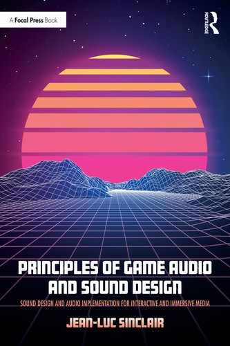
A lot of models have been put forth for reverberation decay over distance by researchers over the years. One such was put forth by W.G. Gardner for Wave Arts inc. (1999), which suggests that for a dry signal with a level of 0dB the reverb signal be about −20dB when the listener is at a distance of zero feet from the signal.
The ratio between both evens out at a distance of 100 feet, where both signals are equal in amplitude, the dry signal dropping from 0 to −40dB and the reverberant signal from −20 to −40dB. Past that point, the proposed model suggested that the dry signal drop by a level of −60dB at a distance of 1,000 feet, while the reverberant signal drops to a level of −50dB or an overall drop of 30dB over 1,000 feet. In other words:
- At a distance of zero feet, if the dry signal has an amplitude of 0dB, the wet signal should peak at –20dB.
- At a distance of 100 feet, both dry and wet signals drop to –40dB; the ratio between both is even.
- At a distance of 1000 feet, the dry signal drops to −60dB while the wet signal plateaus at –50dB.
It is important to note that this model was not intended to be a realistic one but a workable and pleasant one. A more realistic approach is costly to compute and is usually not desirable anyway; if too much reverb is present, it may get in the way of clarity of the mix, intelligibility, or spatial localization.
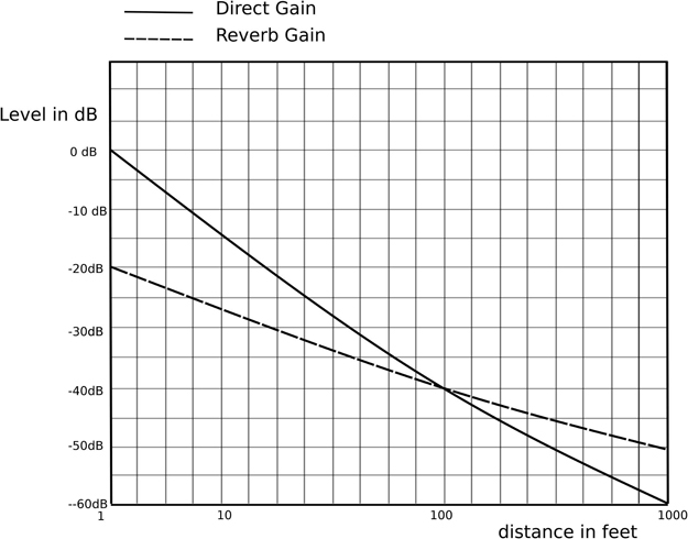
Figure 9.5
Illustration of dry vs. wet signal as a product of distance
Unity’s audio sources include a parameter that allows us to control how much of its signal will be processed by an existing audio reverb zone or zones, the reverb zone mix slider. A value of zero will send no signal to the global audio reverb bus dedicated to reverb zones, and the signal will appear to be dry. A value of 1 will send the full signal to the global bus. The signal will be much wetter and the reverb much more obvious.
This parameter can be controlled via script but also by drawing a curve in the distance graph of an audio source as we did with the low pass filter and spread parameter. When working with reverb zones, this can be a good way to quickly change the dry to reflected signal ratio and increase immersion.
If you are using a mixer setup for reverberation in your scene, you must use automation, discussed in the adaptive mixing chapter.

Figure 9.6
d. Distance Simulation: Putting It All Together
All and all, convincing distance simulation of audio sources in games is achieved by combining several factors, each addressing a specific aspect of our perception of sound. These are:
- Volume: the change in level of an audio source with distance.
- Reverb: the ratio of dry to reverberant signal with distance.
- Frequency content: low pass filtering the audio source with distance,
- The change of perceived width of the audio source with distance.
Figure 9.7
Most game engines will give you the ability to control these parameters, and their careful implementation will usually yield satisfying and convincing results. By carefully implementing these cues, you will create a rich and subtle environment and give the player a consistent and sophisticated way to gauge distance and establish an accurate mental picture of their surroundings via sound.
3. Additional Factors
1. Occlusion, Obstruction, Exclusion
As we’ve seen so far, Unity does not account for geometry when it comes to sound propagation, which is to say that an audio source will be heard through a wall from another room as if the wall wasn’t there, as long as the listener is within range of the audio source. The issue of obstacles between the audio source and the listener uses a combination of raycasting from the audio source to the listener and low pass filtering. This scenario was used to recreate the phenomenon known as occlusion.
There are, however, a number of situations that we should consider when dealing with a physical barrier or barriers between the listener and an audio source and whether the direct, reflected sound or both are obstructed.
a. Occlusion
Occlusion occurs when there is no direct path or line of sight, for either the direct or reflected sound to travel to the listener. As a result, the sound appears to be muffled, both significantly softer as well as low pass filtered. This can be addressed by a combination of volume drop and low pass filtering, as seen in with the smart audio source script. In order to detect an obstacle between the audio source and the listener, we can raycast from the audio source to the listener and look for colliders with the tag ‘geometry’ (the name of the tag is entirely up to the developer; however, it is recommended to use something fairly obvious). If one such collider is detected, we can update the volume and the cutoff frequency of a low pass filter added as a component to the audio source.

Figure 9.8
b. Obstruction
Obstruction occurs when the direct path is obstructed but the reflected path is clear.
The direct path may therefore be muffled, but the reflections ought to be clear. A common scenario would be someone standing behind a column listening to someone speaking on the other side. It’s important to know that, in spite of the obstacle, not all the direct sound is usually stopped by the obstacle. The laws of physics, refraction in particular, tell us that frequencies whose wavelength is shorter than the obstacle will be stopped by the obstacle and not reach the listener, while frequencies whose wavelength is greater than that of the obstacle will travel around the obstacle. Since low frequencies have very long wavelength, a 20Hz sound has a wavelength of approximately 17 meters or 55.6 feet; they tend not to be obstructed while high frequencies are much more easily stopped.

Figure 9.9
Obstruction, as with many aspects of our work, needs not be real-world accurate in order to be convincing and can be approximated by low pass filtering the direct sound but leaving the reflected sound unaffected.
c. Exclusion
Exclusion occurs when the direct path is clear but the reflected path is obstructed.

Figure 9.10
A common scenario would be walking past an open door leading to a reverberant space, such as a large church or cathedral, while the preacher is speaking facing the open doors. If you are on the outside, the path of the direct sound is unobstructed, while the path of the reflected sound is mostly contained within the space.
This can be approximated by lowering the level, possibly filtering the reflected sound and leaving the direct sound unaffected.
Out of these three cases, occlusion, obstruction and exclusion, obstruction is usually the most noticeable and therefore the most critical to implement. The reader is encouraged to refer back to Chapter eight, in the section on smart audio sources in order to look for an instance of occlusion implementation.
2. Distance Crossfades
Sounds that can be heard from a distance, such as a waterfall or thunder, present us with a few unique challenges. That is partly due to the fact that sounds can appear quite different from a distance than they do up close. As we get from afar to very close, naturally loud sound sources, such as a waterfall, tend to exhibit differences in three categories: amplitude, spectral content and spatial perception.
In addition to the obvious effect of distance over amplitude, spectral differences will also appear as a sound gets further and further away. It will sound more and more filtered; high frequencies tend to fade and while low frequencies remain. Indeed, especially over long distances, air acts as a low pass filter. The amount of filtering is a factor of distance, and atmospheric conditions such as air temperature, humidity level and atmospheric conditions. In addition to the overall amplitude dropping and the low pass filtering with distance, so do the details of amplitude modulation present in a sound. That is to say that the differences between the peaks and valleys present in the amplitude of a sound also tend to fade away, and the sound may appear to be slightly ‘washed out’, partly due to the combination of loss of high frequencies and the ratio of dry to reverberant sound increasing with distance. Reverberation can indeed have a smoothing effect on the dynamic range of a sound.
In addition to amplitude and spectral changes, sounds that can be heard over large distances also change in how they appear to be projected spatially. In the case of a waterfall, for instance, from a distance the sound is clearly directional, and you could use the sound itself to find your way to the waterfall. From up close, however, the same sound may not be so easy to pinpoint and, in fact, might not be localizable at all, as it might appear to completely envelop the listener. In other words, from a distance the waterfall might appear to be a 3D sound, but from up close it would turn into a 2D sound. The transition is of course gradual, and as the listener gets closer to the source of the sound, the apparent width of the sound will appear to get larger.
Rather than try to manipulate a single recording to fit both up close and afar sounds, it is usually much more satisfying and believable to crossfade between two sounds – a faraway sound and a close-up one – and change the mix in relation to the distance of the listener to the source. This technique is known as a distance crossfade. To implement it in Unity requires two audio sources and keeping track of the distance of the listener to the source. Distance crossfade implementation was discussed in detail in Chapter eight.
3. Doppler Effect
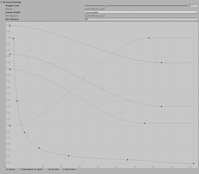
The doppler effect is the perceived shift in pitch as a sound source moves relative to a listener. This is an extremely common occurrence, one that we’re all familiar with. Perhaps the most common example is that of an emergency vehicle with sirens on, driving fast past a person standing on a sidewalk. As the vehicle moves toward us, the pitch of the siren seems to increase, then decrease as the vehicle moves away. This can of course provide us with important information as to the location of moving objects relative to the listener in games. The change in pitch is due to the wavelength of the sound changing as the vehicle or sound source is moving.
Figure 9.11
As the vehicle moves toward the listener, the oncoming sound waves are compressed together, reducing the wavelength and therefore increasing the pitch. Conversely, as the vehicle moves away, the movement from the vehicle stretches the waveform and extends the wavelength, lowering the pitch.
Note: the relationship between frequency and wavelength is given to us by the formula:
Figure 9.12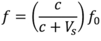
Although the math is helpful to understand the underlying phenomenon, it is provided only as a reference to the reader, since in the game audio business, we are storytellers first and foremost, and accuracy is always second to the narrative.
Unity offers doppler shift control on each audio source individually, and a global control is found in the project settings: Edit->Project Settings->Audio-> Doppler Factor.
The Doppler factor acts as a global setting to emphasize or de-emphasize the Doppler effect on every audio source in the game, the default value being one. The higher the value, the more pronounced the effect will be overall. Values under 1 will reduce the perceived effect.
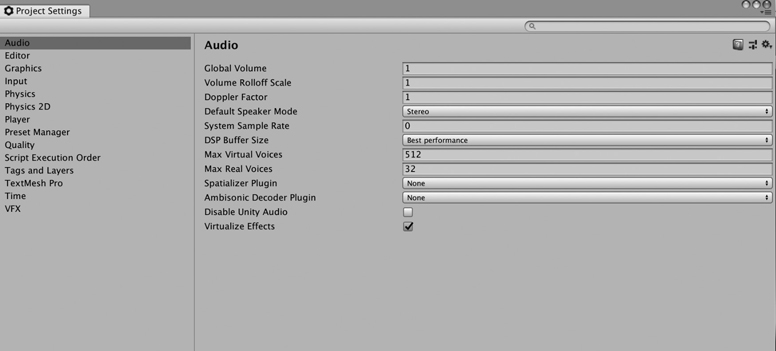
Figure 9.13
Additionally, each audio source’s doppler effect, labelled Doppler Level, can be adjusted individually from the audio source’s 3D settings:

Figure 9.14
The default value for Doppler Level is 1. Increasing this value will increase or exaggerate the perceived shift in pitch for moving audio sources, and, conversely, lowering will make the effect less obvious to nonexistent.
When thinking about how to use the Doppler feature in Unity or any other game engine, remember our motto from Chapter two: inform and entertain. Use the Doppler effect to let the player know when critical elements are in motion and in which direction they are moving, either toward or away from the player. This can be applied to enemy vehicles or drones, large projectiles and anything else the user would benefit from.
Adjusting the value of the Doppler effect for each audio source is to be done on an individual basis in the context of the game and mix. Experimentation is key. Usually you’ll be looking for a balance where the doppler effect is easily noticeable, yet not distracting or even comical. Remember our conversation on immersion in Chapter two; if the effect is too obvious and jumps out in the mix, it will break immersion.
Conclusion
Environmental modeling is as important to game audio as sound design and implementation. Increasingly, as we develop more and more immersive, realistic looking levels and games, the ability for our sounds to exist within an environment that makes their propagation and behavior believable has become all the more important. Being able to address the main issues of distance simulation, spatialization, occlusion and Doppler shift will make every experience you design all the more enjoyable for the user and make your work stand out.