
8.4. PACKET START AND CONTROL SYMBOL DELINEATION
The control framing signal used to delineate the start of a packet or a control symbol on the physical port is a no-return-to-zero, or NRZ signal. This frame signal is toggled for the first 8- or 16-bit datum of each packet and for the first 8- or 16-bit datum of each control symbol (depending on the width of the interface). In order for the receiving processing element to sample the data and frame signals, a data reference signal is supplied that toggles on all possible transitions of the interface pins. This type of data reference signal is also known as a double-data-rate clock. These received clocks on devices with multiple RapidIO ports have no required frequency or phase relationship.
The framing signal is toggled once at the beginning of a packet header or at the beginning of a control symbol. However, it is also toggled for all idle control symbols between packets. This means that the maximum toggle rate of the control framing signal is every four bytes, and the framing signal is only allowed to toggle on every fourth byte. Therefore, the framing signal is aligned to a 32-bit boundary as are all of the packets and control symbols.
Figures 8.6 and 8.7 show the relationship between the data, clock and frame signals for the 8- and 16-bit parallel interfaces, respectively. The framing signal should always toggle on the rising edge of the clock signal.
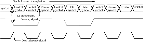
Figure 8.8 shows how consecutive control symbols would be delineated on a 16-bit interface. On the 16-bit interface the control symbol is two beats of data in length and will be transmitted during one clock cycle. The framing signal is an NRZ signal that transitions at the beginning of every control symbol, packet or every fourth Idle packet.
Figure 8.6. Framing signal maximum toggle rate for 8-bit port

Figure 8.7. Framing signal maximum toggle rate for 16-bit port

Figure 8.8. Control symbol delineation example for 16-bit port
Errors on the framing and data reference signals can be detected either directly by verifying that the signals transition only when they are allowed and expected to transition, or indirectly by depending upon detection of packet header or CRC or control symbol corruption, etc if these signals behave improperly. Either method of error detection on the framing and data reference signals allows error recovery. For simplicity, the data reference signal will not be included in any additional figures. It is always rising on the 32-bit boundary when it is legal for the frame signal to toggle.