
7.8. THE ELECTRICAL INTERFACE
It is beyond the scope of this book to present the details of the Serial RapidIO electrical interface. This section will present a brief overview of the techniques used to connect Serial RapidIO devices together and to achieve the extremely high signaling rates of Serial RapidIO. The 1x and 4x links are electrically identical, except for the use of more lanes in the 4x link. Figure 7.24 shows the signal interface diagram connecting two 1x devices together with the RapidIO serial interconnect.
Figure 7.25 shows the signal interface diagram connecting two 4x devices together with the RapidIO serial interconnect.
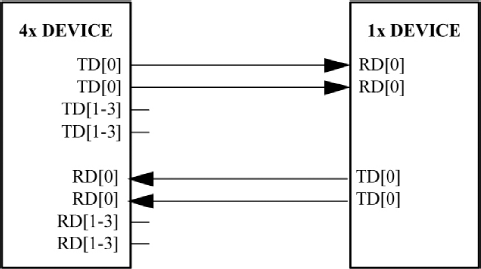
Figure 7.26 shows the connections that would be active between a 4x serial device and a 1x serial device.
Figure 7.24. RapidIO 1x device to 1x device interface diagram

Figure 7.25. RapidIO 4x device to 4x device interface diagram

Figure 7.26. RapidIO 4x device to 1x device interface diagram
The RapidIO specification defines two sets of transmitter electrical specifications (short-run and long-run) and a single receiver specification for each of three baud rates, 1.25, 2.50, and 3.125 Giga baud persecond.
Two transmitter specifications allow for solutions ranging from simple board-to-board interconnect to driving through two separate connectors and across a backplane. A single receiver specification is used. The receiver specification will accept signals from both the short-run and long-run transmitter specifications.
The short-run transmitter should be used mainly for chip-to-chip connections on either the same printed circuit board or across a single connector. This covers the case where connections are made to a mezzanine (daughter) card. The minimum swings of the short-run specification can reduce the overall power used.
The long-run transmitter specifications use larger voltage swings that are capable of more reliably driving signals across backplanes. The long-run transmitter is meant to allow a user to drive the RapidIO signals across two connectors and a backplane, with a total distance of at least 50 cm at all the supported baud rates.
To ensure interoperability between drivers and receivers of different vendors and technologies, AC coupling at the receiver input is required.
Serial RapidIO links use differential signaling. This section defines terms used in the description and specification of these differential signals. Figure 7.27 shows how the signals are defined. The figures show waveforms for either a transmitter output (TD and TD) or a receiver input (RD and RD). Each signal swings between A and B volts where A > B. Using these waveforms, the definitions are as follows:
The transmitter output signals and the receiver input signals TD, TD, RD and RD each have a peak-to-peak swing of A - B V
The differential input signal of the receiver VID is defined as VRD - VRD
The differential output signal of the transmitter and the differential input signal of the receiver each range from A - B to -(A - B) V
The peak-to-peak value of the differential transmitter output signal and the differential receiver input signal is 2(A - B) V

To illustrate these definitions using real values, consider the case of a short-run RapidIO transmitter that has a common mode voltage of 2.25 V and each of its outputs, TD and TD, has a swing that goes between 2.5 and 2.0V. For these values, the peak-to-peak voltage swing of the signals TD and TD is 500 mV. The differential output signal ranges between +500 and −500 mV. The peak differential voltage is 500 mV. The peak-to-peak differential voltage is then 1000 mV.
The parameters for the AC electrical specifications are guided by the XAUI electrical interface specified in Clause 47 of IEEE 802.3ae-2002. XAUI is an IEEE standard for use in 10-Gigabit Ethernet applications. XAUI has similar application goals to serial RapidIO. The goal of the RapidIO work is that electrical designs for Serial RapidIO can reuse electrical designs for XAUI, suitably modified for applications at the baud intervals and reaches as described.