You've constructed your biped robot. Now, your robot can move around. But what if you want the robot to sense the outside world, so you don't run into things? In this chapter, you'll discover how to add some sensors to help avoid barriers.
Specifically, you'll learn:
Your robot can now move around, but you'll want to be able to sense a barrier or a target. One of the ways to do this is with an IR sensor. First, a tutorial on IR sensors is required. An IR sensor has both a transmitter and a sensor. The transmitter sends out a narrow beam of light, and the sensor receives this beam of light.
The difference in transit ends up as an angle measurement in the sensor, as shown in the following figure:
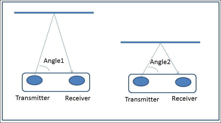
The different angles give you an indication of the distance from the object. The sensor turns these angle measurements into a voltage that you can sense to determine the distance. Unfortunately, the relationship between the output of the sensor and the distance is not linear, so you'll need to do some calibration in order to predict the actual distance and its relationship to the output of the sensor.
Before you get started, you'll need to get a sensor. One of the more popular ones is an inexpensive IR sensor by Sharp. It is available at many online electronics stores, and it comes in models that sense various distances. You'll be using the Sharp 2Y0A02 model, a unit that provides sensing to a distance of 150 cm. Here is a picture of the sensor:

You'll also want to make sure you also get the connector cable for the device; it normally comes with the device. Here is a picture of the sensor with the cable attached:

As noted in the tutorial, the voltage out of the sensor will be a voltage that will be an indication of the distance. However, this is an analog signal, and the Raspberry Pi doesn't have an analog-to-digital converter that can convert this analog voltage to a number that you can read in your program. You'll need to add an analog to digital converter to your project.
There are two choices. If you want an analog-to-digital converter that plugs directly into the USB interface, there is one offered by www.phidgets.com. This board is really quite amazing; it takes the analog signals, turns them into digital numbers using an analog to digital converter, and then makes them available so that they can be read from the USB port. The model number of this part is 1011_0 - PhidgetInterfaceKit 2/2/2 and it is shown in the following:

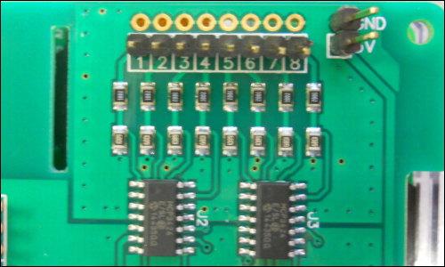
Unfortunately, it takes a bit of programming expertise to get it up and running. The other choice is to use an analog-to-digital converter that connects to the GPIO pins of the Raspberry Pi. There is a part, the ADC pi+ from www.abelectronics.co.uk, that does this. It is pictured here:

This device is easier to program, so this is what you'll use in this project. Now, let's connect the sensor:
- Solder header pins to the ADC Pi+ board to connect it to the ADC, like this:
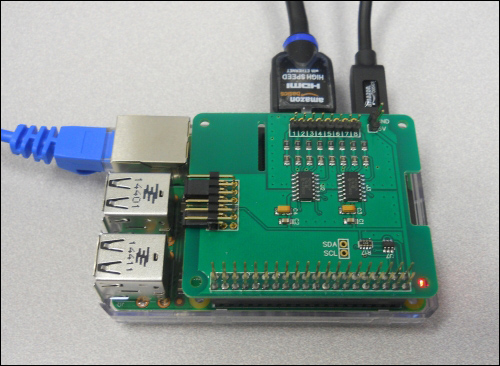
- Now, plug the board into the Raspberry Pi B 2. Here is a picture of the combination:
- Now, you'll connect the IR sensor to the ADC. To connect this unit, you'll connect the three pins that are available at the bottom of the sensor. Here is the connection list:
ADC-DAC Board
Sensor Pin
5V
Vcc
GND
Gnd
In1
Vo
Unfortunately, there are no labels on the unit, but here are the pins you'll connect:

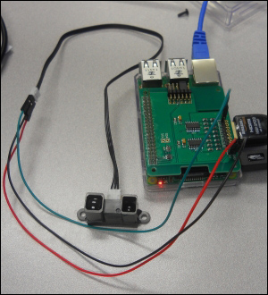
It's easiest to connect to the three-wire cable that normally comes with the sensor. Once the pins are connected, you are ready to access the data from the sensor via a Python program on the Raspberry Pi. The entire system looks like this:
Now, you are ready to add some code to read the IR sensor. You'll need to follow these steps to talk to the ADC:
- The first step in enabling the ADC is to enable the I2C interface. This is done by running
raspi-configand selecting 8 Advanced Options like this: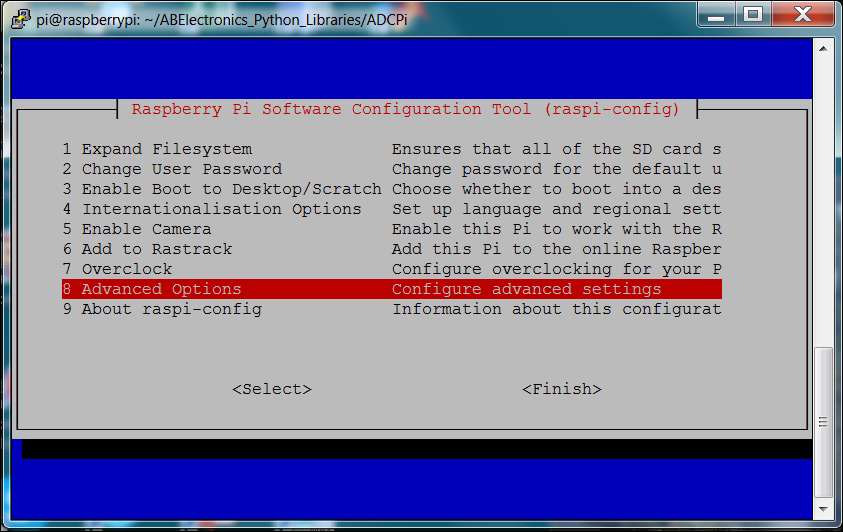
- Once there, go to the A7 I2C selection to enable the I2C like this:
Perform all the selections to enable the I2C interface and load the library, and then reboot the Raspberry Pi.
You'll also need to edit the
/etc/modulesfile and add the following two lines:
Reboot the Raspberry Pi. You can see whether the I2C is enabled by typing
sudo i2cdetect -y 1, and you should see something like this:
The I2C device, your ADC, is available at the 68 and 69 addresses.
- Now, you can download the code. To do this, type
git clone https://github.com/abelectronicsuk/ABElectronics_Python_Libraries.gitfrom the home directory, and the Python libraries will be installed on your Raspberry Pi. - Go to the
./ABElecttronics_Python_Libraries/ADCPidirectory; here are the programs for your specific hardware. Following the instructions in theREADME.mdfile, typesudo apt-get update, and then typesudo apt-get install python-smbus. This will install thesmbuslibrary, which are required for the ADC to work. Also, typesudo adduser pi i2cto addpito the group that can access i2c. - You'll need to edit your
.bashrcfile in your home directory, adding the following lines:
Adding this line will add this library to the path so that you can access the functionality. Reboot the Raspberry Pi.
- Now, you can run one of the demo programs. Type
python demo-readvoltage.py, and you should see something like this:
These raw readings are great, but now you'll want to build a program that takes the data from the first ADC and translates it to the distance. To do this, you'll need a graph of the voltage to distance readings for your sensor. Here is the graph for the IR sensor in this example:

There are really two parts to the curve; the first is the distance up to about 15 centimeters, and the second is the distance from 15 centimeters to 150 centimeters. It is easiest to build a simple mathematical model that ignores distances closer than 15 centimeters and models the distance from 15 centimeters. For more information on how to build this model, refer to http://davstott.me.uk/index.php/2013/06/02/raspberry-pi-sharp-infrared/. Here is the Python program using this model:

The only new line of code is the distance = (1.0 / (adc.read_adc_voltage(1) / 13.15)) - 0.35 line. It converts your voltage to distance. You can now run your program and you'll see the results in centimeters, like this:

Now, you can measure the distance to objects using your IR sensor!