
Now that your biped is up and mobile and able to find barriers, you can now start to have it move around autonomously. However, you'll want to have your robot planed his path, that is, if it knows where it has started and the desired end point, it can move from the starting point to the end point.
In this chapter, you will be learning about:
- How to add a compass to your biped, so you'll have a sense of direction
- Learning some basic path planning techniques for your robot
One of the important pieces of information that might be useful for your robot, it if is going to plan its own path, is its direction of travel. So, let's learn how to hook up a digital compass to the Raspberry Pi.
There are several chips that provide digital compass capability; one of the most common is the HMC5883L 3-Axis Digital Compass chip. This chip is packaged onto a module by several companies, but almost all of them result in a similar interface. The following is a picture of one the GY-271 HMC5883L Triple Axis Compass Magnetometer Sensor Module, which is available from a number of online retailers:
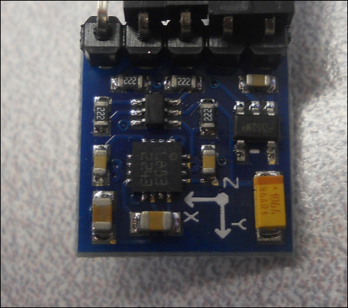
This type of digital compass uses magnetic sensors to discover the earth's magnetic field. The output of these sensors is then made accessible to the outside world through a set of registers that allow the user to set things such as the sample rate, and continuous or single sampling. The x, y, and z directions are output-using registers as well.
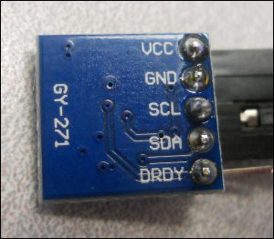
The connections to this chip are straightforward and the device communicates with the Raspberry Pi by using the I2C bus, a standard serial communications bus. The I2C interface is a synchronous serial interface and provides more performance than an asynchronous Rx/Tx serial interface. The SCL data line provides a clock, while the data flows on the SDA line. The bus also provides addressing so that more than one device can be connected to the master device at the same time. On the back of the module, the connections are labeled, as shown in the following image:
You'll then connect the device to the GPIO pins on Raspberry Pi. The following is the pin out of Raspberry Pi:
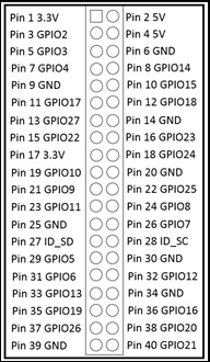
Connect your device to the VCC on the device to Pin 1 (3.3 V) on Raspberry Pi. Connect GND to Pin 9 (GND). Connect SCL on the device to Pin 5 (GPIO 3) and SDA to Pin 3 (GPIO 2) on the device. Notice that you will not connect the Data Ready (DRDY) line. Now, you are ready to communicate with the device.