CHAPTER 6
Solar Thermal Systems – Year-Round Heating from the Sun
The light and warmth of the sun give us a special sense of well-being, which is why summer is eagerly awaited in the colder regions of the world such as Northern Europe. Most people in these countries are also lucky enough to be able to reproduce these conditions even in the depths of winter. Our homes and workplaces are heated to a comfortable level and well lit, and our water is heated, so that we can enjoy hot baths and showers at any time. The luxury of always being able to set the desired temperature is taken for granted today, one of the most pleasant achievements of our prosperous society. It is difficult to imagine the period after the Second World War, when not enough fuel was available in the cold winters to maintain even reasonably bearable temperatures in our dwellings. However, our prosperity and fossil fuels have eliminated these conditions once and for all – not everywhere in the world but at least for us (Figure 6.1).
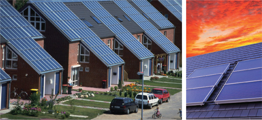
Figure 6.1 Modern solar thermal collector systems are an important alternative to conventional oil and natural gas heating.
Photos: http://www.wagner-solar.com.
But even eliminating fossil fuels will in no way jeopardize our privilege of always being able to select the temperature we want. Solar thermal energy – the heat from the sun – is an important alternative. Solar thermal energy covers a wide range of applications. When sunlight shines through windows, the power of the sun is already helping to warm up the building. For centuries, the sun has been a major source of heat for our homes.
In 1891 the metal manufacturer Clarence M. Kemp from Baltimore was awarded the first patent in the world for a technical solar thermal system. This was a very simply constructed storage collector for heating water. In 1909 the Californian, William J. Bailey introduced an optimized system concept that separated the solar heat collector from the water storage cylinder. Solar heating systems were marketed successfully in certain regions until the Second World War, after which the market collapsed because of competition from fossil fuels.
It was not until the oil crises in the 1970s that solar thermal power was rediscovered. In the years that followed there were still many teething problems, and not all systems ran smoothly. Today a variety of solar thermal system variants are available, and these systems are much more sophisticated than in the past. In combination with optimized heat insulation and other renewable heating systems, such as biomass heating and renewably operated heat pumps, these systems can make an important contribution towards the supply of carbon-free heat.
 Solar Collector, Solar Absorber, Solar Cell or Solar Module
These terms are often used interchangeably, so to avoid confusion it is important to be clear about what exactly they refer to.
A sun collector or solar collector is used to extract heat from the radiation of the sun. Thus, a collector always makes something hot. At the heart of a solar collector is a solar absorber. The solar absorber absorbs the radiation of the sun and converts it into heat. Solar collectors are used to heat domestic water, supplement space heating and produce high-temperature process heat. Thermal power plants can even generate electricity from high-temperature heat (see Chapter 7). However, even then solar collectors are first used to produce the heat.
A solar cell is a photovoltaic cell that converts solar radiation directly into electric energy (see Chapter 5). Although a solar cell can also get hot, it is different from a solar collector in the sense that this is an undesired side effect. The heat actually reduces efficiency during the production of electricity. A solar module consists of a large number of solar cells and also generates electric energy from sunlight.
6.1 Structure and Functionality
Solar thermal energy is a technology for converting solar radiation into heat. The field of application for this technology is extensive. The higher the temperatures are required to be, the more complicated the technical implementation. The principle is similar with all solar thermal systems. A solar collector first collects the sunlight. The term collector comes from the Latin word ‘collegere’, which means to collect. The main component of a collector is the solar absorber. It absorbs the sunlight and converts it into heat (Figure 6.2). It then transfers this heat to a heat transfer medium.
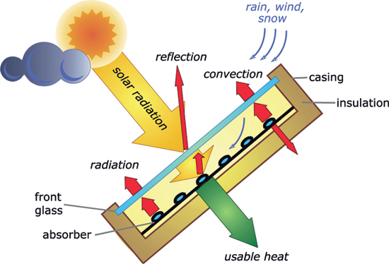
Figure 6.2 Processes in a solar flat-plate collector [Qua13].
The heat transfer medium may simply be something like water, air, or even oil or salt. Heat loss is unavoidable during the conversion. Part of the solar radiation is reflected and does not even reach the absorber. A certain amount of heat is lost before it can be transferred to the heat transfer medium. The trick is to construct a collector, so that heat loss is as low as possible, but the collector is still cost-effective to produce. Appropriate collectors should be used depending on the field of application and the desired temperatures.
The efficiency curve describes the performance of a collector. Research institutes measure collectors under strictly defined conditions to determine the curve. These characteristic curves can then be obtained from the manufacturer of the collector or over the Internet.
![]()
|
Swiss collector test reports German collector test reports (in German) |
 Collector Efficiency
The efficiency and efficiency curve of a solar collector can be determined using the three parameters |0, a1, and a2. The optical efficiency |0 describes which portion of sunlight is converted into heat by the absorber. The absorber itself or the front panel of glass actually reflects a portion of the sunlight before it can even be absorbed. Depending on the type of collector, optical efficiency is between 70% and 90%. The two loss coefficients a1 and a2 indicate how high the heat loss is in the collector. The hotter the collector is, the higher the heat loss and the less useful heat the collector can emit. High loss coefficients also mean high heat loss. The formula for collector efficiency is as follows:
Here Δϑ indicates the temperature difference between the collector and the environment and E the intensity of the solar radiation.
With an ambient temperature of 25 °C and a collector temperature of 55 °C, the result is a temperature difference of Δϑ = 30 °C or 30 K. On a pleasant summer's day with a solar radiation intensity of E = 800 W m−2, the calculation of a flat-plate collector with an optical efficiency of η0 = 0.8 and the loss coefficients k1 = 3.97 W (m2 K)−1 and k2 = 0.01 W (m2 K2)−1 gives a collector efficiency of
A collector 4.88 m2 in size then supplies 2500 W of power. This is sufficient to heat 100 l of water from 33.5 to 55 °C in one hour.
The collector efficiency curve describes the relationship between the efficiency and the temperature difference between the collector and the environment (Figure 6.3). It shows that efficiency drops as the temperature rises until the collector reaches an efficiency of zero and zero output.
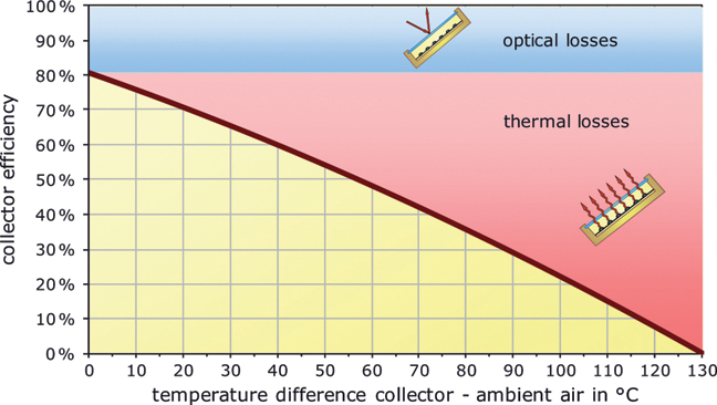
Figure 6.3 Collector efficiency curve.
Almost all thermal solar systems require storage in addition to a collector. There are very few cases when the sun shines at exactly the same time as heat is needed. Even a simple water tank can function as a thermal store. It should be well insulated to reduce heat loss. The storage size depends mainly on the heat requirement and on how long the heat needs to be stored. Daytime storage cylinders for hot water systems in single-family homes are designed to bridge a few days of demand and usually only hold a few hundred litres. If, in addition to hot water, very large quantities of heat also need to be stored for heating, then seasonal heat storage cylinders are required. These store heat in the summer and then release it again in the winter. Large heat storage cylinders for small housing estates reach sizes of several hundred or even thousand cubic metres. Large storage cylinders generally have less specific heat loss than small ones. The storage volume increases considerably faster than the size of the storage surface. However, storage losses depend only on the size of the surface of the storage.
6.2 Solar Collectors – Collecting the Sun
6.2.1 Swimming Pool Absorbers
Different types of collectors are available for different purposes. The simplest type of collector consists of only one absorber. Placing a dark garden hose filled with water in the sun for a time produces enough heated water for a short but warm shower. A garden hose thus already has the characteristics of an absorber. In principle, a professional swimming pool absorber is also nothing more than a simple black plastic pipe that absorbs the sunlight almost optimally due to its dark colour. Weather-resistant plastics that cope well with UV light and chlorinated pool water are used for this purpose. The materials that are suitable are polyethylene (PE), polypropylene (PP) and ethylene-propylene-dien-monomere (EPDM). PVC should be avoided for ecological reasons. In winter it is futile trying to use a garden hose to extract warm shower water. The same applies to swimming pool absorbers. Although an absorber continues to absorb the sun's radiation, the heat loss in the absorber pipe itself is so great that hardly any heat can be drawn from the end of a pipe. Technically more sophisticated collectors are required to use the sun's heat during winter and the transitional periods of the year or when water temperatures should be warmer than the water in a swimming pool.
6.2.2 Flat-Plate Collectors
With flat-plate collectors a front panel of glass reduces heat loss considerably. Unfortunately, the front glass also reflects some of the sunlight. Therefore, when collector temperatures are very low, the efficiency of a swimming pool absorber can be higher than that of a flat-plate collector. However, flat-plate collector efficiency increases considerably as temperatures rise.
In summer, there are times when solar thermal systems do not need any heat. For example, when a heat storage cylinder is completely full the system does not pump any more water through the collector. This is referred to as a collector standstill. The temperatures in collectors can easily rise above 100 °C. Very good flat-plate collectors reach standstill temperatures between 150 and 200 °C. This therefore rules out the use of plastic pipes for absorbers. The absorbers of flat-plate collectors usually consist of copper or aluminium pipes fixed to a thin metal plate (Figure 6.4). The absorber itself is located in a collector enclosure that is well insulated at the back to minimize rear heat loss.

Figure 6.4 Cross-section of a flat-plate collector.
Image: Bosch Thermotechnik GmbH.
Metallic materials by nature do not have a black surface that absorbs the sun's radiation well, so they need to be coated. The first option that is usually considered for the coating is black paint. Although temperature-resistant black paint is good for this purpose, there are other, far better materials for absorber coating. When a black surface gets warm, it sends out some of the heat energy in the form of thermal radiation. This can be observed with an electric hot plate that has been switched on. One can feel the heat radiating from the hot plate without even touching it. The same effect occurs with a black-painted absorber. The absorber only radiates part of its heat to the water flowing through. Another part is emitted back into the environment as undesirable thermal radiation.
Thermal radiation losses can be minimized through the use of selective coatings (Figure 6.5). These coatings absorb the sunlight just as well as a black-painted plate. However, they emit a much lower amount of thermal radiation. Materials for selective coatings can no longer simply be painted or sprayed onto a surface. More complicated coating methods are now necessary.
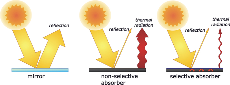
Figure 6.5 Principle of selective absorbers.
6.2.3 Air-Based Collectors
In most cases, solar collectors heat water. However, for space heating what we actually require is warm air. With conventional heating systems, radiators or heating pipes installed under the floor transfer the heat produced from hot water to the air. Instead of water, air can be heated directly by a solar collector.
As air absorbs heat considerably less effectively than water, much larger absorber cross-sections are required. Otherwise, in principle, air-based collectors differ very little from liquid-based flat-plate collectors. Figure 6.6 shows an air collector with a ribbed absorber. An integrated photovoltaic module can deliver the electricity to drive the fan motor. Air-based collectors are a particularly interesting alternative for auxiliary heating. However, heat storage is more difficult with systems that use air-based collectors.
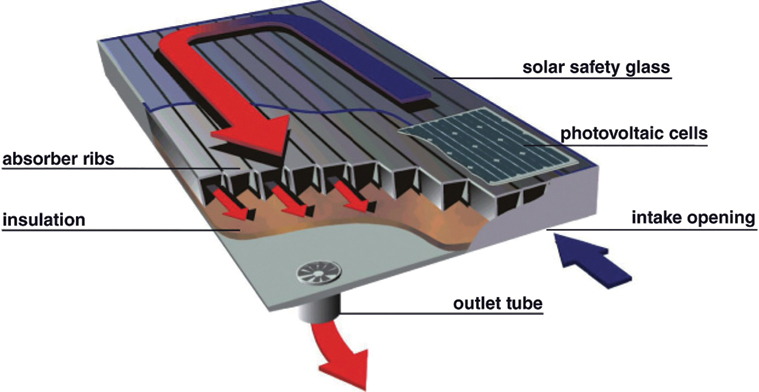
Figure 6.6 Cross-section of an air-based collector.
Image: Grammer Solar GmbH.
6.2.4 Vacuum-Tube Collectors
With flat-plate collectors the air between the absorber and the front glass panel is the source of most of the heat loss. It causes convective heat loss and continuously transports the heat from the absorber to the glass panel. This then emits the heat unused back into the environment.
How an Inflated Plastic Bag Can Be Evacuated
The term vacuum originates from the Latin word ‘vacus’, which means ‘empty’ or ‘free’. A vacuum is generally thought of as space empty of matter. However, it is practically impossible to produce a totally air-less space on earth.
In technology and in physics a vacuum is interpreted merely as air pressure that is considerably lower than normal air pressure. To produce a vacuum, one uses a vacuum pump to pump the air out of a stable space. In principle, it is also possible to use one's mouth to produce a rough vacuum – for example, by sucking the air out of a glass bottle. However, a plastic bag cannot be evacuated – at least not in any normal environment on earth. On the other hand, an almost perfect vacuum exists in space. If one opens an empty plastic bag in space and then closes it again, there will also be a vacuum in the blown-up bag. If one returns to earth with the bag, the ambient air pressure compresses it again.
Ambient air pressure originates through the power of the weight of air columns above the earth's surface. The atmospheric air weighs around 10 t m−2 of earth surface. The question is, why doesn't this enormous pressure simply smash the glass of a collector? The answer is simple: the space under the glass is also filled with air, which produces the necessary counterpressure. On the other hand, if the air in the space behind the glass is evacuated, the glass will normally bend and shatter.
Heat losses can be reduced considerably if a vacuum exists between the absorber and the front glass due to the air movement in the collector. This is the principle used by vacuum flat-plate collectors. As the outer air pressure would press the front covering against the absorber, spacers are needed between the underside of the collector and the glass covering. The vacuum cannot be kept stable for a long period because penetration of air where the glass and collector housing intersect cannot be completely prevented. Therefore, vacuum flat-plate connectors must be evacuated again at certain intervals. This is done by attaching a vacuum pump to a special valve on the collector. These drawbacks were the reason why vacuum flat-plate collectors never became popular.
Another type of collector available is the vacuum-tube collector, which does not have the same disadvantages as the vacuum flat-plate collector. With vacuum-tube collectors, a high level of vacuum is completely enclosed in a glass tube. Consequently, these collectors are considerably easier to produce and maintain for long periods than vacuum flat-plate collectors. The shape of the glass tubes enables them to better withstand outside air pressure so that metal rods are not necessary for support.
In the enclosed glass tube of a vacuum tube collector is a flag absorber, which is a flat metal absorber that has a heat pipe integrated in the middle (Figure 6.7 left). A lightly vaporizing medium like methanol is enclosed in this heat pipe. If it vaporizes due to the heat of the sun, the vapour rises upwards. The heat pipe sticks out of the glass tube at the top end. This is where the condenser, which condenses the heat medium again, is located. In the process, it transfers the heat energy over a heat exchanger to the water flowing through. After condensation the once-more liquid medium in the heat pipe flows downwards. For maximum functionality the tubes should be mounted with a certain minimum tilt.
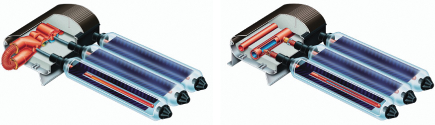
Figure 6.7 Vacuum tube collectors. Left: Collector with heat pipe. Right: Tube with direct flow.
Images: Viessmann Werke.
With this system the heat carrier liquid flows directly through the collector. A heat exchanger is then not required, and the collector does not necessarily have to be mounted at an angle.
Because hydrogen molecules are extremely small, atmospheric hydrogen cannot be totally prevented from penetrating the vacuum. With time this also destroys the vacuum. So-called getters, which can chemically bind the hydrogen that penetrates the vacuum over a long period of time, are built into a collector to prevent this from happening.
The advantage of vacuum-tube collectors is a very high energy yield, especially during the cooler seasons of the year. Compared to one with normal flat-plate collectors, a solar system with vacuum-tube collectors requires less space for the collector. The disadvantage is the substantially higher cost of the collector (Figure 6.8).

Figure 6.8 Comparison of flat-plate and vacuum-tube collectors.
Photo: Viessmann Werke.
6.3 Solar Thermal Systems
6.3.1 Hot Water from the Sun
The sun can be used to heat water to a high temperature. This is something we learned from Archimedes, who used a convex mirror to bring water to the boil as far back as 214 BCE. That's not surprising, some will say, because Archimedes was not from Hamburg, London, or Vancouver. In Southern Italy it is simply easier to use the sun's energy. This is quite correct, but only up to a point.
Average temperatures in the Mediterranean region are much higher than in Germany, Great Britain, or Canada and there is no worry there about frost damage to hot water systems. Systems that use solar energy to produce hot water can be constructed more simply and thus more cheaply in frost-free regions than in colder climates. However, even at high latitudes solar energy is an excellent option for producing useful heat.
6.3.1.1 Gravity Systems
However, the fact that the use of solar energy should be virtually obligatory in southern countries has not yet spread everywhere. In other words, at similar latitudes the number of systems installed varies considerably between countries. Thermal solar systems are common in Cyprus, Turkey, and Israel but not in Spain or the southern USA, although these areas also have a sunny climate.
Gravity systems are mainly used in countries that do not get frost (Figures 6.9 and 6.10). A flat-plate or vacuum-tube collector collects the solar radiation and heats water that flows through the collector. A hot water storage cylinder is installed at a higher level than the collector. As cold water is heavier than warm water, it sinks down from the storage cylinder to the collector. Here the water is heated by the sun and then rises to the top until it reaches the storage cylinder again. If no more solar radiation is available, the cycle stops until the sun starts it up again.

Figure 6.9 Left: Demonstration model of a gravity system. Right: Gravity system in Spain.
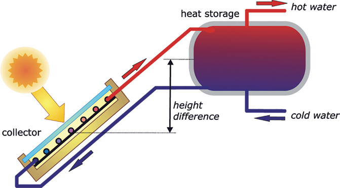
Figure 6.10 Solar gravity system (thermo-syphon system).
If properly designed, this kind of solar system can cover almost all the hot water needs of a family living in a warm, sunny, southern climate. It is only during some of the sun-starved weeks of the year that the water will not completely reach desired temperatures. Either this is accepted in those countries or a supplemental heater, for example, with natural gas, is installed. If on occasion the heat of the sun is not sufficient, a supplemental heater then takes over.
In China solar thermal systems for heating water have gained a high market share. In remote rural regions there is almost no access to fossil fuels. The inhabitants of these regions do not have the possibility of heating their water as and when required if there is no sun. China uses mainly vacuum-tube collectors because of the need to guarantee high supply reliability from solar systems at low ambient temperatures.
6.3.1.2 Systems with Forced Circulation
A system should be technically optimized if the sun is to be used to produce hot water in areas with low outdoor temperatures. It would be too risky to heat up water for domestic use directly in a collector because the water would freeze in winter and therefore could destroy the collector. Consequently, the water that flows through the collector is mixed with an antifreezing agent. However, antifreezing agents cannot be used in the water supply, as they have negative effects on health. A heat exchanger therefore separates the water circulation from the solar circulation and transfers the heat to a hot water storage cylinder. The storage cylinder is normally designed so that it can provide enough hot water for two to three bad days until a major supply of heat comes from the solar collector (Figure 6.11).

Figure 6.11 Single-family house with photovoltaic system (left) and flat-plate collectors for heating water (right).
Photo: SunTechnics.
Flat roofs are less common in Central and Northern Europe and North America than they are in Southern Europe. Hot water storage cylinders are traditionally located in a basement or in a utility room. If the hot water storage is situated below the collector, the water must be pumped through the collector. A pump moves the water in a solar circuit through the collector and a control mechanism ensures that the pump only starts when the temperature of the collector is higher than that of the storage cylinder (Figure 6.12). A conventional boiler heats up the water during the transitional seasons and in winter, so that a hot shower is possible all year round. It can happen that during the summer a solar collector will heat up an entire storage cylinder to a predetermined maximum temperature. This maximum temperature is usually set at 60 °C to prevent large deposits of lime from forming. If the cylinder is full, the control interrupts the incoming supply from the collector. Despite full irradiation from the sun, no more water will flow through the collector. The collector can then heat up to temperatures well over 100 °C and evaporate the water. If the expansion tank is large enough, it absorbs the expansion of the water volume.
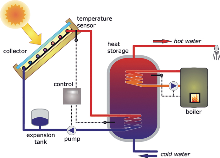
Figure 6.12 Pumped solar thermal system for heating domestic hot water.
6.3.2 Heating with the Sun
Solar thermal systems can be used to provide not only hot water but also heating. In principle, this only requires increasing the sizes of the collector and the storage cylinder and connecting them to the heating cycle. As no provision is normally made for domestic hot water in the heating cycle, two separate heat storage cylinders are needed – one for hot water and the other for drinking water. Combined-storage tanks can integrate both storage elements and reduce heat losses (Figure 6.13).
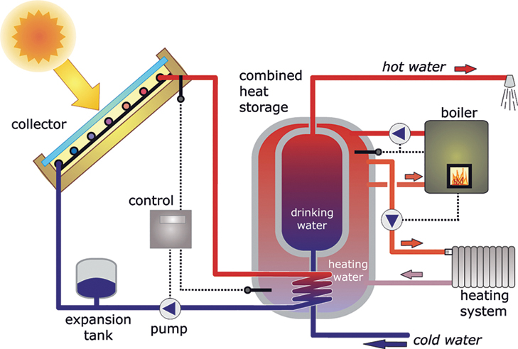
Figure 6.13 Solar thermal system for domestic hot water heating and auxiliary space heating.
In places like Germany and Great Britain the sun is only able to meet heating demand during the transitional periods of spring and autumn. Consequently, these systems are usually designed so that solar energy only serves as a supplemental heat supply. The output of the collectors is not sufficient to cover the heat needed during the winter. In principle, the sun could be used to cover all heating requirements. However, this necessitates a very large storage cylinder that stores thermal heat from the summer for the winter and due to its size can usually only be integrated into new buildings. Although this considerably increases the costs for the solar system, there is then no need for an additional heating system. For economic reasons, current practice tends to use tanks that can cover only a few days. Such systems enable between 20% and 70% of the heat demand to be covered by the sun (Figure 6.14).
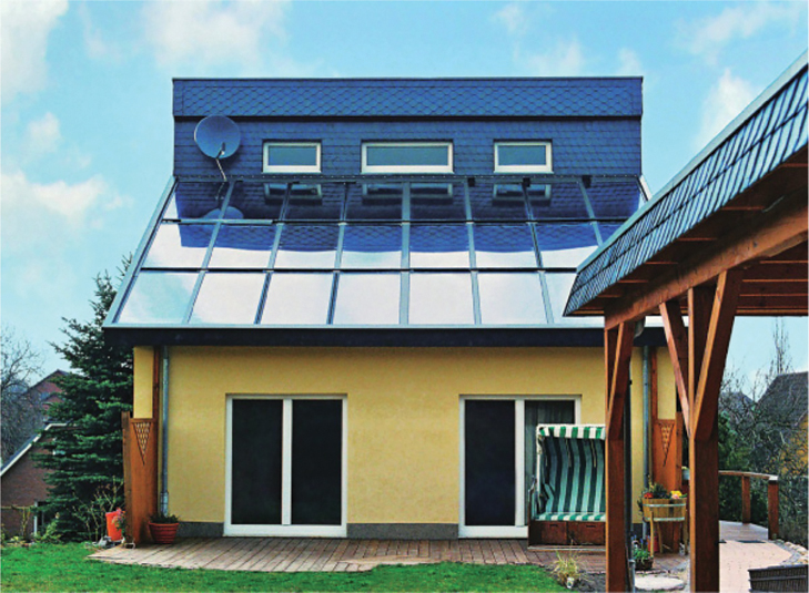
Figure 6.14 Large roof-integrated solar thermal system for heating water and providing supplementary heating.
Photo: SunTechnics.
Solar coverage rates of 20–30% are relatively easy to achieve for standard new buildings and even renovated old buildings. However, buildings with higher solar fractions are also needed in order to completely convert the heating sector to renewable energies for effective climate protection throughout Germany and elsewhere. To achieve this, the building must be optimally insulated and brought up to passive house standard. In a normal single-family house, 40–50 m2 of collector surface and around 10 000 l of storage volume are then sufficient to achieve a solar fraction of 65%, even in less sunny locations. The remaining heating energy demand can then be covered quite easily with a wood-burning stove, for which 1–2 m3 of firewood per year are sufficient. The annual heating bill is then usually less than €200 (Figure 6.15).
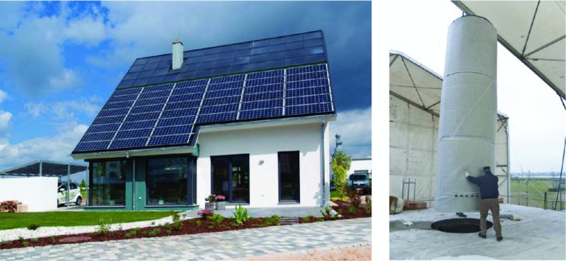
Figure 6.15 In the energy self-sufficient solar house (left) in Lehrte, a 46 m2 solar thermal system with a 9300 l buffer storage tank (right) covers 65% of the heat demand and an 8 kW PV system covers the entire electricity demand.
Photos: HELMA Eigenheimbau AG.
If the entire heating energy demand is to be covered by the sun, even larger collectors and storage tanks are required. Numerous successful solar houses in Germany and Switzerland have already proven that this is possible in principle. In a normal single-family home, the required collector size is around 80 m2 and the storage tank size around 40 000 l.
6.3.3 Solar Communities
If many houses in a community have solar collectors, these can be integrated into a solar district heat network. This can also involve setting up a large central collector complex. At the heart of such a heat network is a central heat storage tank. Its size helps to minimize heat losses, thus also enabling heat to be stored for longer periods. However, the extensive tube systems involved can result in disadvantages, such as higher costs and the possibility of major line losses.
Several solar district heating systems have already been successfully installed. Europe's largest solar thermal project is currently located in Marstal, Denmark. A collector area of around 19 000 m2 has been installed in the project, which has been implemented in various construction phases. A storage capacity of 15.5 million litres is available through a combination of a storage tank, a storage pond and a gravel store. The solar heat is distributed via a local heating network and covers around 32% of the heat demand of over 1400 customers (Figure 6.16).

Figure 6.16 Solar community heating system.
6.3.4 Cooling with the Sun
As paradoxical as it may sound, the heat from the sun can also be used to provide excellent cooling for buildings. In the hot and sunny regions of the world large numbers of energy-hungry air conditioning systems ensure that room temperatures are pleasantly cool. The sunnier and hotter it is, the greater the need for cooling. As the radiation from the sun increases, the output of a thermal collector also increases. In contrast with the requirement for heat, cooling load demand coincides almost perfectly with the supply of the sun.
Along with a large and efficient collector, an absorption-refrigerating machine is an essential element of a solar cooling system (Figure 6.17). In this context, the term absorption does not refer to a solar absorber. An absorption-refrigerating machine utilizes the chemical process of sorption. A chemist interprets sorption or absorption as the absorption of a gas or a fluid by another fluid. A popular example is the dissolution of carbon dioxide gas in mineral water.
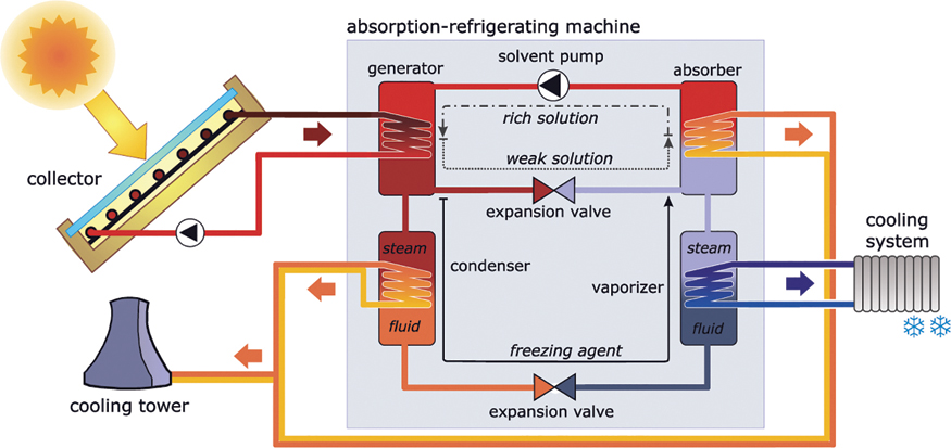
Figure 6.17 Principle of solar cooling with absorption chillers.
Absorption-refrigerating machines use a cooling agent with a low boiling point, such as ammonia, which is later dissolved in water. Even aside from ammonia, water itself under low pressure can be used as a cooling agent. Lithium-bromide is then suitable as the solvent.
The cooling agent boils in a vaporizer at low temperatures. In the process it extracts the heat from the cooling system. The cooling agent must then be liquefied again so that it can provide continuous cooling through renewed evaporation. With the help of a few tricks and an indirect way through sorption, the liquidation also succeeds through the use of solar heat.
The cooling machine absorber first mixes the cooling agent vapour with the solvent. This produces sorption that releases the heat. This heat is either used to heat the water or is transferred to a cooling tower. The liquid solution, which has been enriched with a cooling agent, is transported to the generator by a solvent pump. The generator separates the cooling agent and the solvent on the basis of their different boiling points. Heat from efficient solar collectors is used for the boiling process. Temperatures of 100 –150 °C are optimal. The separated vaporous cooling agent then enters a condenser, which liquefies the cooling agent. The condensation heat is also dissipated either as useful heat or over a cooling tower. The liquid cooling agent enters the vaporizer over an expansion valve and the solvent returns again to the refrigerating machine absorber. The cooling agent cools down considerably through the expansion in the expansion valve, and can again deliver cooling to the cooling system over the vaporizer.
6.3.5 Swimming with the Sun
During the outdoor swimming season in Central Europe water temperatures normally reach 16–19 °C. The water is only warmer than this for a few days during the height of summer, although this period is becoming longer because of global warming. These water temperatures are a result of swimming pool water being heated by the sun. The following example shows how enormous is the energy content of the sun. The example uses Lake Constance, a lake popular for swimming that is visited by millions of tourists annually. In winter the lake cools off quite considerably and in 1880 and 1963 it was even completely frozen over. In summer, in contrast, it reaches a temperature high enough to attract hordes of swimmers. If the entire supply of coal consumed in Germany each year were used to heat the water, it would only be enough to heat up the 50 km3 of water of Lake Constance just once to a temperature of 9 °C. Looking at the USA, the whole US American primary energy supply of one year would only suffice to heat up Lake Michigan by less than 5 °C on a single occasion.
The sun, on the other hand, can provide pleasant water temperatures without a problem and can do so over many weeks. Despite the heat of the sun, many bathers still find swimming pool temperatures too low in summer, so that pools are artificially heated. And because we only have to heat up a small swimming pool, and not all of Lake Constance or Lake Michigan, many places pull out all the stops. In Germany there are about 8000 public outdoor and indoor swimming pools. In addition, there are around 500 000 private pools. In the USA there are about 8.6 million pools in total and 270 000 commercial pools. Several hundred million euros are spent each year alone to heat public pools. Yet alternatives are available that would definitely enable us to use the sun to save fuel costs and considerably reduce the emission of carbon dioxide.
Outdoor swimming pools are particularly suitable targets for the use of solar energy. The popularity with bathers and the supply of solar energy are a perfect match. Simple swimming pool absorbers heat up pool water directly. A pump conveys the water through an absorber and a simple control ensures that water is only pumped when the sun actually can heat it up (Figure 6.18). If the water were pumped through the absorber tube at night as well, this would result in the pool water being cooled again. A good half-square metre of solar absorber surface is needed per square metre of pool area. The surface space that is needed is often found on buildings near the pool. Covering a pool at night can save further energy.
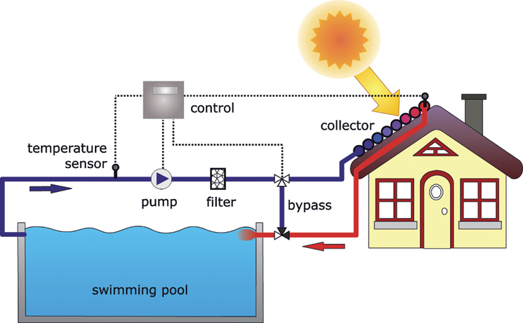
Figure 6.18 System for swimming pool heating using solar energy.
6.3.6 Cooking with the Sun
In many countries cooking is still often done on an open wood fire. About 2.5 billion people around the world use this traditional method to prepare their meals. From the energy point of view, however, an open fire is anything but efficient. Firewood does not last long. In many countries wood is cut down at a faster rate than trees can grow back. Furthermore, the smoke produced by open fires is responsible for many illnesses. In sunny countries solar cookers offer an alternative to traditional hearths.
A solar cooking box is a very simple cooking system: a wooden box painted black inside that is covered with a sheet of glass angled in the direction of the sun. This very simple solar collector is actually capable of heating water and food. However, it is not very efficient, and the glass cover makes it difficult to prepare food. An efficient solar cooker is a neater solution. With a solar cooker, the cooking pot is situated in the middle of a convex mirror. The mirror is moved approximately every quarter-hour, so that it is directed optimally towards the sun. With a mirror diameter of 140 cm and good sun radiation, it is possible to bring 3 l of water to the boil in about half an hour (Figure 6.19).
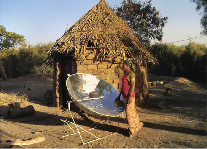
Figure 6.19 Solar cooker in Ethiopia.
Photo: EG Solar e.V., http://www.eg-solar.de.
6.4 Planning and Design
Of all the solar thermal systems described, the systems that use solar heat to heat up domestic water and to supplement other heating systems are the most widely used. The planning tips are therefore limited to these two variants.
6.4.1 Solar Thermal Heating of Domestic Hot Water
6.4.1.1 Outline Design
In Germany, Britain and other temperate regions, solar thermal domestic hot water systems are normally designed so that on a yearly average the sun covers 50–60% of the hot water demand. As the amount of sunshine in these regions fluctuates considerably during the year, a solar system can usually only cover the total hot water demand during the summer months. In the winter, the solar share can fall below 10% (Figure 6.20). A conventional heating system then has to cover the rest. In sunny regions like California and Southern Europe the solar share can easily reach more than 80%.
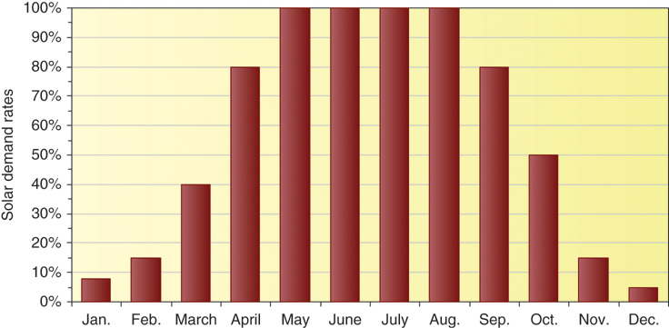
Figure 6.20 Typical solar fractions of solar thermal drinking water systems over the year.
In order to further increase the solar fraction over the year, the expenditure would have to be increased significantly. Doubling the size of the system will not double the solar fraction. Only in the summer months could the solar system meet double the demand. With the usual relatively small storage tanks, however, this surplus heat cannot be used. In winter, the share of solar energy would also increase. But if you double less than 10%, the share remains low.
A simple rule of thumb for designing solar thermal systems to provide domestic hot water, based on the number of people in a household, is:
- collector size. 1–1.5 m2 flat-plate collectors per person; and
- storage capacity. 80–100 l per person.
If vacuum-tube collectors are used, the collector size can be around 30% smaller. The collectors should not be less than 3–4 m2 in area, because below this size the losses in the tubes increase to above average.
6.4.1.2 Detailed Design
The hot water demand has to be determined before a detailed design can be drawn up. Ideally, the system should include a hot water meter that provides a direct reading of actual consumption or a record listing hot water use over a long period of time. As a rule of thumb, the demand can be approximated based on a hot water temperature of 45 °C:
- Low consumption. 15–30 l or 0.6–1.2 kWh per person per day
- Average consumption. 30–60 l or 1.2–2.4 kWh per person per day
- High consumption. 60–120 l or 2.4–4.8 kWh per person per day.
Storage Capacity and Hot Water Demand
The storage capacity, Vstorage should be about twice the total demand of P persons with a daily requirement Vperson per person:
Based on the hot water demand Qperson per person per day, the annual hot water demand QHW for the supply of hot water can be calculated as:
The tank size for a four-person household with an average consumption of 45 l or 1.8 kWh of hot water per day would thus be:
Typical tank sizes are 300 or 400 l. A 400-l tank would be more than adequate in this case. A 300-l storage falls somewhat below the calculated demand but is still sufficient. The annual heating demand is:
Collector Size
Once the size of the storage cylinder has been established, the collector size Acollector is calculated. This calculation also requires the annual figures for radiation Hsolar and tilt gains ftilt (cf. Section 5.4). With an annual solar fraction sf and an average system efficiency of 30% with systems using flat-plate collectors, the collector size Acollector can be calculated as follows:
In this formula a solar fraction of 0.6 should be chosen for European climates (e.g. Berlin or London) and 0.9 for very sunny climates such as California. In this scenario, the collector size for flat-plate collectors should be calculated on the basis of a roof in Berlin orientated about 20° towards the south-southwest and tilted by 30°. The annual solar radiation in this case amounts to 1075 kWh (m2 a)−1 and the southern orientation produces tilt gains of ftilt = 110% = 1.1. As a result, the required surface for flat-plate collectors is calculated as

The results, of course, depend heavily on the quality of the collectors and can vary considerably. Some online tools are available to help with system design (see web tips). Sophisticated computer programs are necessary to improve the detailed planning. Professional firms specializing in this field should also be able to provide detailed system designs. In addition to determining the size of the collector and the storage, their services include the design of other components such as pumps, controllers and pipes.
![]()
|
Online calculations for solar thermal systems |
6.4.2 Solar Thermal Auxiliary Heating
A large collector surface is needed if a solar thermal system is to provide support heating in addition to domestic hot water. In contrast to the supply of hot water, this option requires optimal building insulation to enable the sun to provide a larger share of the heat requirement. Whereas hot water use is relatively constant throughout the year, heating needs are concentrated in the winter months. However, the yield from solar collectors is low in the winter. Therefore, solar thermal systems that supply support heating are usually designed so that, in addition to hot water, they can cover only a portion of the heating required during the transitional period from March to October. In winter conventional heating systems essentially provide the heating required (Figure 6.21).
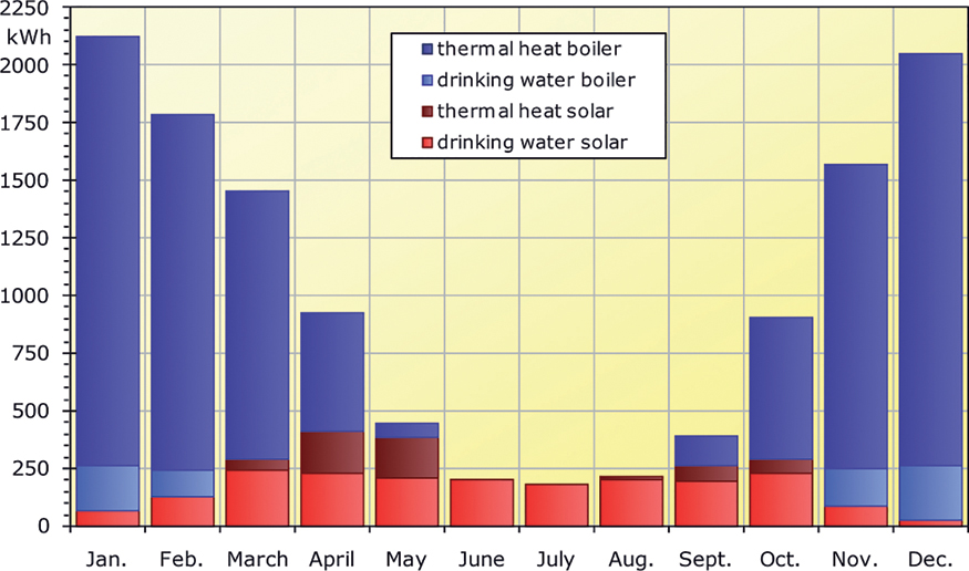
Figure 6.21 Typical monthly space heating and hot water demands in Germany and proportion of solar system versus conventional heating based on the demand of an old building with a total solar fraction of 20%.
The size of the collector surface and the storage also affect the degree of solar coverage, and thus the proportion of heat covered by the sun. This also reduces the share a conventional heating system provides. If a fossil system fired with oil or gas is used, then the carbon dioxide emissions drop in accordance with the size of the solar system. However, a very large system also produces a higher surplus that cannot be used. Therefore, as a rule, large systems are less economical than small ones. So, when it comes to design, one must consider whether the priority is maximum input from the sun or economic viability.
The following two design options provide the basis for an outline design in Central European climates:
Option 1. Small system for good efficiency
- Collector area with flat-plate collectors: 0.8 m2 per 10 m2 living space;
- Collector area with vacuum tube collectors: 0.6 m2 per 10 m2 living space;
- Tank size: at least 50 l m−2 of collector area.
Option 2. Medium-sized system for higher solar fraction
- Collector area with flat-plate collectors: 1.6 m2 per 10 m2 living space;
- Collector area with vacuum tube collectors: 1.2 m2 per 10 m2 living space;
- Tank size: 100 l m−2 of collector area
An optimal design would of course also take into account the actual heating energy demand. The difference in requirements between an old building and an energy-saving three-litre house is considerable. Table 6.1 shows simulation results for optimal systems that were dimensioned according to the outline design described.
Table 6.1 Solar fractions
| Existing building | New building pre-2010 | Three-litre house | Passive house | |
| Domestic hot water demand in kWh | 2700 | 2700 | 2700 | 2700 |
| Heating energy demand in kWh | 25 000 | 11 500 | 3900 | 1950 |
Solar fraction, option 1 (small system) |
13% | 22% | 40% | 51% |
Solar fraction, option 2 (medium-sized system) |
22% | 36% | 57% | 68% |
Assumptions: Berlin location, orientation 30° south without shade, 130 m2 living area, optimal flat-plate collector with combined-storage tank.
Although the collector with the medium-sized system is double the size of the small system and the storage is four times larger, this does not mean that the solar fraction is twice as high. The insulation standard of a building has considerably more influence on the solar fraction than these two elements. Optimal insulation options should be considered when the aim is to increase the solar fraction as a way of contributing towards climate protection.
From Thinking about a Solar Thermal System on the Roof to Installing a System
-
Determine the orientation and tilt angle of the roof.
Is the roof suitable in terms of orientation and tilt angle?
Recommendation: at least 95% according to Figure 5.15.
Does the roof have too much shade? - Decide whether only water for domestic use should be heated or whether solar heating or cooling support is also required.
- Outline design following rule of thumb.
- Possibly detailed design based on manual calculations or using simulation tools.
- Apply for appropriate approvals for listed buildings.
- Request quotations.
- Have the design specified by a specialist company.
- Apply for subsidies or low-interest loans (see following section).
- Award contract for the work.
6.5 Economics
6.5.1 When Does It Pay off?
Depending on type and design, between €200 and €350 m−2 should be estimated for flat-plate collectors and between €400 and €600 m−2 for vacuum-tube collectors in Central Europe. A 300-l heat storage cylinder costs around €700–1100. Installing a solar thermal system can be especially cost-effective in new buildings, or when an existing hot water storage cylinder is old and has to be replaced anyway. The costs for a solar thermal system fall within a wide range. A system purely for domestic hot water with 4 m2 flat-plate collectors and a 300-l hot water storage cylinder can be acquired for as little as €2000, not including installation. The average cost of a European system for a four-person household excluding installation is between €3000 and €l3400; a system including installation is around €5000. Depending on the size of the collector, the cost of a system that provides support heating can be double or even higher. Government grants are sometimes available to help cover the costs.
Even if the investment costs for a solar thermal system are known, getting a handle on the economics is difficult compared to photovoltaics (PV). The output of a photovoltaic system can be tracked accurately through an electricity meter and the statement for the fed-in electricity will show in euros and cents whether a system is living up to the planners' promises.
The output of a solar thermal system can also be monitored with a heat volume meter. However, in practice, these are hardly ever used because of cost. In very sunny countries a solar thermal system can cover the total demand. The cost-effectiveness is also usually high in these cases. In colder climates solar thermal systems are almost always supplemented by conventional heating systems, which make up for what the lack of sunshine cannot cover. No direct compensation is given for the heat output yield of a solar thermal system. A system only pays for itself indirectly through the savings in the fuel costs of the heating system. It is mainly the movement of fuel prices that establishes whether a system is paying for itself and at what rate. The higher fuel prices climb, the faster a solar thermal system will pay for itself. If, on the other hand, fuel prices fall, the economic viability of a solar system is less favourable.
Figure 6.22 shows the payback periods for a typical solar thermal system for heating domestic water. This is the time it takes for the fuel costs a system has saved to break even with the investment costs. If hot water is heated electrically for around €0.25 kWh−1, the system will be pay for itself quite quickly. The payback becomes more challenging with particularly high-quality and expensive systems when fuel prices are low. In this case public grant programmes could be available to improve the economy of these systems.
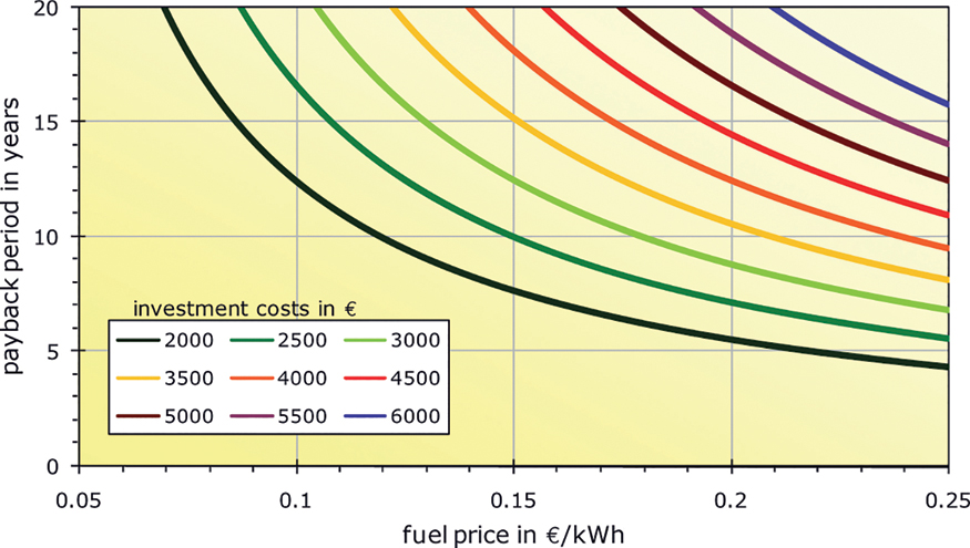
Figure 6.22 Payback periods for a solar thermal domestic hot water system with backup heating system (without interest rate effects and price increases; fuel savings: 2000 kWh a−1, annual operating costs: 2% of capital costs).
6.5.2 Funding Programmes
In Germany, support for solar thermal systems is currently mainly provided through the Federal Government's market incentive programme, which is handled by the Federal Office of Economics and Export Control (BAFA). In the past, the funding rates were regularly adjusted to the number of applications. The application for funding should be submitted before construction begins. The process is relatively straightforward. The subsidy is paid directly, once the system has been installed.
In addition to support at federal level, there are also local support programmes in individual federal states. Low-interest loans, which are granted by the federally owned KfW development bank, can also be considered for some system options.
![]()
Interactive support advisor German Federal Office for Economic Affairs and Export Control KfW development bank |
6.6 Ecology
Solar thermal systems are among the most environmentally compatible renewable energy systems. They normally save on fossil fuels such as oil and natural gas, and thereby actively contribute towards climate protection. The collectors are mostly integrated into buildings and, consequently, do not require any extra land. The materials used in solar thermal systems – such as glass, copper, and plastic – are for the most part just ordinary materials commonly used in standard construction. Although environmentally problematic materials, such as polyurethane foam or PVC are also used in some solar collector systems, many collector manufacturers deliberately dispense with these materials.
Energy is needed to manufacture solar thermal systems. In Central Europe, it takes between six months and two years before a solar thermal system delivers the same amount of energy that was used in its production. This period is shorter in countries with a lot of sunshine. Many manufacturers place a great deal of emphasis on environmental protection and renewable energies during the production of thermal solar systems. The zero-emissions Solvis factory in Braunschweig, Germany, is an example.
Some attention needs to be paid to the size of electrical pumps in solar systems. These pumps require electric energy to operate. However, this requirement for auxiliary energy is usually smaller, by many orders of magnitude, than the energy saved by a solar system. Photovoltaic systems can be used to enable the auxiliary electric energy required by solar thermal systems to be covered directly by the sun.
Many solar thermal systems also use chemicals such as antifreeze or cooling agents. Typical antifreeze products like Tyfocor L have a minimal effect on water quality, and, therefore, are largely safe for the environment.
Special protective measures are required if ammonia is used for solar cooling in absorption-refrigerating machines. Ammonia is toxic and dangerous to the environment. Ammonia that escapes can bind to water. Lithium-bromide is also harmful to human health, but less so than ammonia.
6.7 Solar Thermal Markets
In terms of world markets for solar thermal collectors, one country puts all the rest to shame: China. Around 442 million square metres of collectors were installed in the country in 2015. These collectors deliver about 309 GW of heat power. The Chinese collector market thus accounts for over 70% of the entire world market (Figure 6.23).
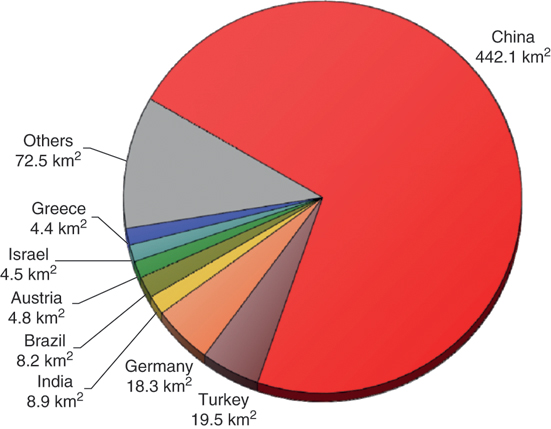
Figure 6.23 Installed glazed collector area in different countries. 2015.
Source: Data: [SHC17].
With its widespread use of solar thermal energy, China has developed into a market leader in collector manufacturing. More than 1000 companies now produce and distribute solar collectors in China. Around 150 000 people were employed in the solar thermal energy sector in the year 2000 in China [EST03]. In contrast to many other countries, China specializes in highly efficient vacuum tube collectors rather than the simple flat-plate collectors. Due to the large number of units produced for the Chinese market, Chinese suppliers are very competitive internationally. Most of the vacuum-tube collectors sold in the world come from China.
In the EU, Germany dominates the solar collector market. If one considers solar thermal collector area installed per head, small countries have the edge. In Cyprus, almost every house has a solar thermal system on it. In 2015 this Mediterranean island had around 679 000 m2 of collector area distributed among just 1.1 million inhabitants. Statistically, this means there are nearly 606 m2 of solar collectors per 1000 Cypriots. In Austria, by comparison, this figure is 595 m2. Greece has around 400 m2. Germany, on the other hand, only reaches 229 m2 per thousand inhabitants and sunny France just 33 m2. Local market conditions and acceptance by the population both have considerably more influence on the amount of installed collector area than the supply of solar radiation.
Germany is an example of how political conditions can affect markets. Until 2001 there was continuous market growth. In 2002 the market suffered a setback because of changes in incentive conditions and associated market insecurity (Figure 6.24). In 2008, the exploding oil price caused a brief boom in solar thermal energy, although this quickly evaporated again with falling oil prices. Since then, the solar thermal market has been under strong pressure due to low oil prices and is declining despite all the climate protection ambitions.
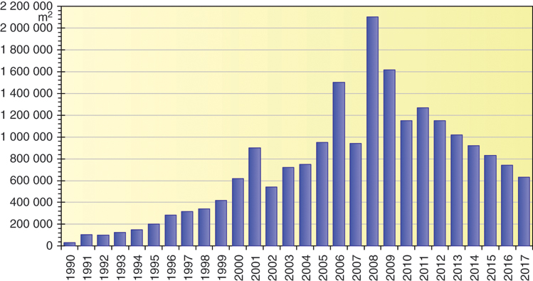
Figure 6.24 Annual newly installed collector area in Germany.
Source: Data: [BSW18].
By the end of 2017, a total of 2.3 million solar thermal systems with a total area of 20.6 million square meters had been installed. In the same year the solar thermal sector in Germany accounted for over 10 000 jobs. The solar systems save the emission of around two million tons of carbon dioxide each year. Although this is an impressive number, it still falls far short of saving the climate.
6.8 Outlook and Development Potential
During the past 15 years the solar thermal market in Europe has increased more than 10-fold. A few years ago, there were still quite optimistic estimates for future market development. According to these, the market for new installations was expected to increase to 8 million square metres per year by 2030 [BSW12] (Figure 6.25).
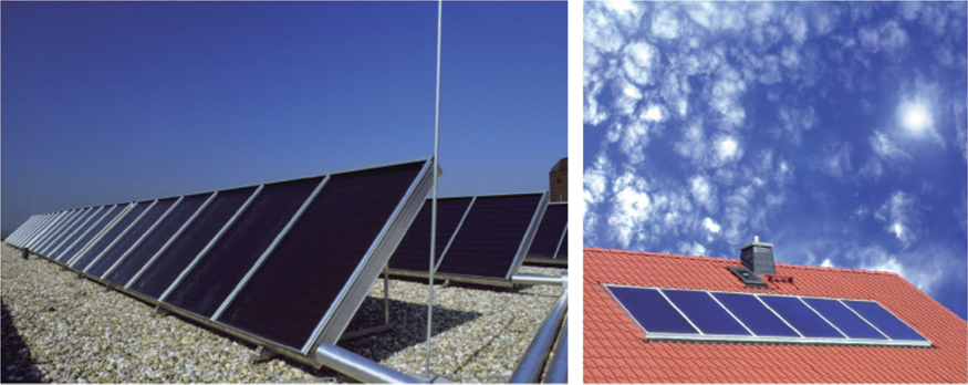
Figure 6.25 Many roofs still have space for solar collectors.
Source: Photos: wagner-solar, http://www.wagner-solar.com
That would be around 10 times as much as in 2017. The number of employees in the solar thermal sector could then grow to over 50 000 in Germany alone. From today's perspective, however, this estimate seems too optimistic. While the costs for PV systems have fallen drastically in recent years, solar thermal energy has only been able to achieve comparatively small cost reductions and thus not achieve a major cost advantage over oil and gas heating.
In the meantime, solar thermal energy in Germany is in direct competition with photovoltaics. It could be that in the future a PV system will be installed on many houses instead of a solar thermal collector system and coupled to the heating system via a heating rod or a heat pump. Ultimately, it does not matter how solar energy is used for climate protection. The key is that our energy supply is completely covered by renewable energies as soon as possible. The potential is much greater in the sun-rich countries of the world. Due to the considerably higher economic efficiency, solar thermal energy could achieve a double-digit percentage share of the heat market there (Figure 6.26).
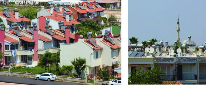
Figure 6.26 In some regions of the world, for example in southern Turkey, simple and thus inexpensive solar thermal systems already cover a large part of the heat demand.