
CHAPTER 11
Heat Pumps – From Cold to Hot
Due to the rise in oil and petrol prices during recent years and increasing public awareness of climate and pollution problems, alternatives such as wood pellet heating, solar thermal systems, and heat pumps are becoming more popular. Manufacturers of heat pump systems have recorded strong growth since 2000.
Yet, the whole principle behind the heat pump is far from modern. Lord Kelvin, a British physics professor, already proved this principle in 1852. He also established that a heat pump uses less primary energy to provide heat than a system that produces heat directly. A heat pump uses a heat source with low temperatures and increases it to a higher temperature (Figure 11.1). This process requires an electric, mechanical, or thermal drive.
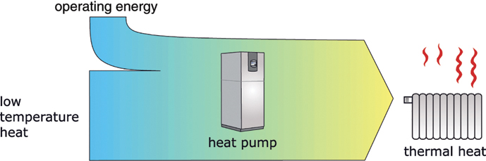
Figure 11.1 Energy flow with a heat pump process.
11.1 Heat Sources for Low-Temperature Heat
A heat pump is basically a machine in which a mechanically or electrically driven pump generates heat from a low-temperature source. This heat is then used to provide space heating or to produce hot water. Before a heat pump can even function, a low-temperature source must be available. The higher the temperature level of the heat source, the more efficiently the heat pump can work.
The following heat sources are available for homes (Figure 11.2):
- Groundwater (water/water);
- Ground, ground heat exchanger/collector (brine/water);
- Ground, ground probe (brine/water); and
- Ambient air (air/water or air/air).
The waste heat from industrial plants can also be used.
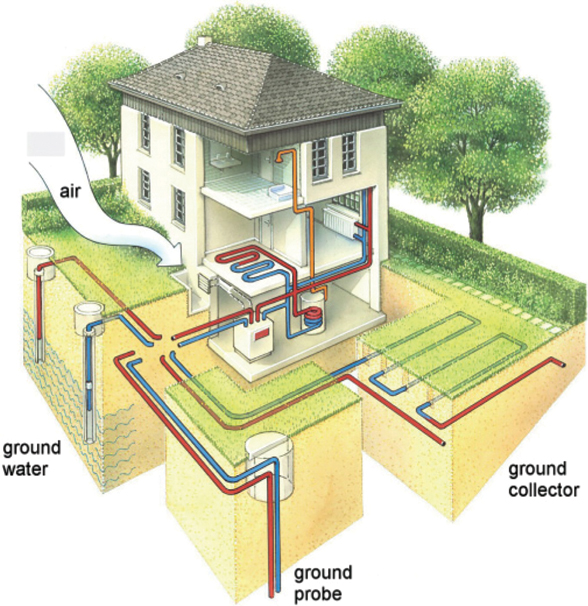
Figure 11.2 Heat sources for heat pumps. Illustration: Viessmann Werke.
Depending on the heat source, heat pumps fall into the categories of air/air, air/water, brine/water, or water/water systems. The heat medium supplied is indicated in front of the forward slash. In the case of ambient air, it is air. In the case of constantly frost-free groundwater, it is water. Because of the risk of frost, a mixture of water and antifreeze, called brine, flows through the pipes in the ground.
The heat medium given after the forward slash is that of the delivered heat. In most cases, heat pumps heat up water for heating and domestic use. They are rarely used to heat the air for air heating systems.
The higher the temperature of the heat source and the lower the temperature needed for heating, the less electric energy is required to drive the heat pump. Due to the low heating temperatures, underfloor heating is preferable to conventional radiators.
 Coefficient of Performance (COP) and Seasonal Performance Factor (SPF)
The ratio of instantaneous transmitted heat flow ̇![]() to instantaneous, usually electrical, input P is called the coefficient of performance or COP:
to instantaneous, usually electrical, input P is called the coefficient of performance or COP:
The electrical input P and the thermal input ![]() of the low-temperature heat source together produce the heat flow
of the low-temperature heat source together produce the heat flow ![]() :
:
For example, if a heat pump with an electrical input of P = 3 kW generates a heat flow of ![]() , the COP is 3. The difference of
, the COP is 3. The difference of ![]() derives from the low-temperature heat source.
derives from the low-temperature heat source.
The COP only applies to instantaneous values. The annual average is interesting and is called the seasonal performance factor, or SPF for short.
A high SPF is essential for the environmentally compatible and economical operation of a heat pump. With an SPF of 4, for example, a heat pump can cover a heating demand of 10 000 kWh yr−1 using only 2500 kWh of electric energy. With an annual performance coefficient of 2, the electric energy consumption rises to 5000 kWh.
Very good systems reach SPF values of around 4. In practice, the values are often below this. Table 11.1 shows typical SPF values for different types of heat pumps from a field test in the Black Forest.
Table 11.1 Typical annual performance coefficients for electric heat pumps [Lok07]
| Heat pump | Heat source | SPF with underfloor heating | SPF with radiators |
| Brine/water | Ground | 3.6 | 3.2 |
| Water/water | Groundwater | 3.4 | 3.0 |
| Air/water | Air | 3.0 | 2.3 |
Heat pumps that draw their heat from the ground produced the best values. The SPF values for groundwater heat pumps were somewhat lower. The reason is that it takes more pumping effort to extract groundwater than it does to exploit heat from a closed brine loop in the ground. Furthermore, dirt traps in groundwater wells eventually become blocked, which further increases the amount of pumping energy needed. As ambient air temperatures in winter are lower than ground or groundwater temperatures, air-based heat pumps work least efficiently at that time of the year.
11.2 Operating Principle of Heat Pumps
All heat pumps need a refrigerant contained in a closed loop. The refrigerant absorbs the low-temperature heat. The heat pump then heats up the refrigerant to a higher temperature, which is then utilized. Based on the operating principles, a distinction is made between:
- compression heat pumps;
- absorption heat pumps; and
- adsorption heat pumps.
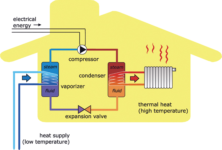
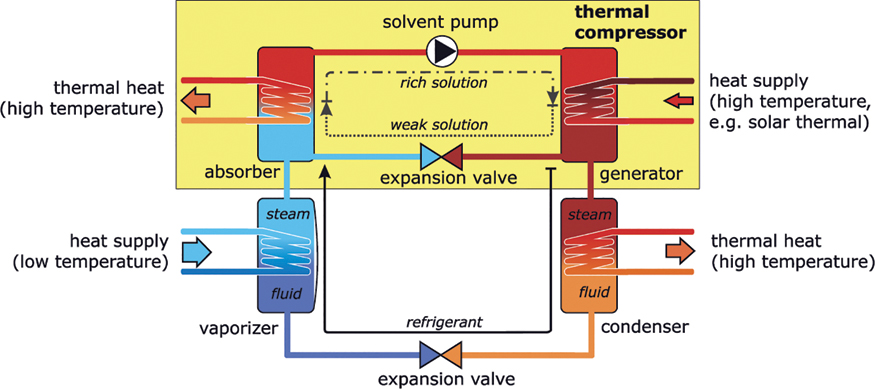
Compression heat pumps are by far the most common type (Figure 11.3). The principle of these heat pumps is based on a refrigerant with a low boiling point that vaporizes at low temperatures and reaches high temperatures when it is compressed (Table 11.2). The heat supplied from the low-temperature source in the vaporizer is sufficient for vaporization. Figure 11.3 Operating principle of a compression heat pump. Table 11.2 Temperature ranges of common refrigerants A compressor (usually electrically driven) brings the vapour-forming refrigerant to a high operating pressure. During this process it heats up considerably. This process is similar to what happens with a bicycle pump when one uses one's thumb to stop the air escaping while energetically pumping a tyre. The heat of the heated refrigerant is then used as useable heat, usually for room heating or heating water. The heat is removed through a condenser that again liquefies the refrigerant. The refrigerant that is compressed expands over an expansion valve, cools off and is transferred to the vaporizer again. Heat pumps are also used in refrigerators, where they act as refrigerating machines. A vaporizer removes the heat from the interior of a refrigerator. The heat is emitted over cooling fins on the back of the appliance. The heat emitted there comprises the heat removed from the refrigerator and the electrical operating energy of the refrigerator compressor. The refrigerator emits more heat at the back than it extracts from the inside, which is why it is not possible to cool down a room in the summer by leaving the refrigerator door open. The first compression refrigerating machine was developed by the American Jacob Perkins in 1834. He used ether, which is no longer used today, as a refrigerant for his ice-making machine. The refrigerant ether has the disadvantage that in combination with atmospheric oxygen it forms a highly explosive mixture. This occasionally caused ether ice machines to explode. Like compression heat pumps, absorption heat pumps use low-temperature heat to evaporate a refrigerant. However, absorption heat pumps use a thermal compressor instead of the electrically driven compressor used in compression heat pumps (Figure 11.4). Figure 11.4 Operating principle of absorption heat pumps. The function of a thermal compressor is to compress and heat the refrigerant. This happens through a chemical process of sorption, for example through the dissolving of ammonia in water. This was explained in the section ‘Cooling with the sun’ in Chapter 6. The heat released through sorption can be used as thermal heat. A solvent pump transports the solution to the generator. The solvent pump, unlike the compression heat pump, does not build up high pressure, so a relatively low amount of electrically driven energy is needed. The generator now has to separate the water and refrigerant ammonia in the solution again to enable the sorption to take place once more. High temperature heat is needed for the expulsion. Solar heat and biogas can be used. The high temperature heat supplied is well below the dissipated quantity of useful heat. The main advantage of absorption heat pumps is that they use a very small amount of valuable electric energy. They are particularly useful for large-scale applications. They are also used as refrigerating machines in refrigerators run with propane gas. The refrigerant ammonia is toxic and flammable. However, it is a widely used chemical and is considered easy to control. Adsorption heat pumps, which only differ by the second letter from absorption heat pumps, likewise use thermal energy as the operating energy. What is meant by adsorption is that a gas like water vapour attaches itself to a solid material, such as activated carbon, silica gel, or zeolite. The process of adsorption, i.e. the bonding of the water vapour by the solid material, creates high temperatures that can be utilized by a heat pump. However, adsorption heat pumps are still at the research stage and therefore will not be covered in detail in this book.11.2.1 Compression Heat Pumps
Abbrev.
Name
Boiling point at 1 bar (°C)
Condensation temperature at 26 bar (°C)
R12
Dichlordifluormethane
−30
86
R134a
1,1,1,2-Tetrafluorethane
−26
80
R290
Propane
−42
70
R404A
Mixture of different HFCs
−47
55
R407C
Mixture of different HFCs
−45
58
R410A
Mixture of different HFCs
−51
43
R600a
Butane
−12
114
R717
Ammonia
−33
60
R744
Carbon dioxide
−57
−11
R1270
Propene
−48
61
![]() The Reverse Refrigerator
The Reverse Refrigerator11.2.2 Absorption Heat Pumps and Adsorption Heat Pumps
11.3 Planning and Design
Today heat pumps are available for almost any thermal output required. Manufacturers usually provide advice on selection and design. The most important aspect in planning is the selection of a low-temperature heat source and how to exploit it.
If a heat pump is to be installed in a groundwater protection area, no groundwater is allowed to be drawn. Approval for the use of a deep-ground probe to utilize the heat from the ground is only given in special cases as the brine could contaminate the groundwater if there were a leak. In Switzerland, for example, there are installations of ground probes in water conservation areas where carbon dioxide (R744) replaces the brine.
Using ambient air as a heat source is the simplest and most cost-effective approach. This is not even a problem in groundwater protection areas. No approvals are necessary to install and operate air/water or air/air heat pumps in these areas. Basically, all these heat pumps need are two openings in a house wall through which the ambient air can be fed to the heat pump. Condensation forms if the outside air is very cold and should be allowed to drain off in a controlled way. Heat pumps can also easily be installed outdoors. Air/water heat pumps function at ambient temperatures as low as −20 °C. A supplementary electric heater helps to ensure that the necessary heat supply is covered when temperatures are particularly extreme. A small buffer storage unit can optimize the operating times of a heat pump. The disadvantage of using ambient air is that the SPFs are relatively low. This significantly increases the electricity consumption compared with other heat sources.
Brine/water heat pumps, in other words heat pumps that extract heat from the ground, use the least amount of electricity. Either ground collectors or ground probes are used to extract the heat. A ground collector usually comprises a set of plastic pipes that are laid in a serpentine pattern in the soil. The optimal depth for the pipes is 1.2–1.5 m, and the gap between pipes should be about 80 cm.
Size of the Ground Heat Collector
The length l and the area A of a ground collector is calculated from the required refrigerating capacity ![]() of the low-temperature heat source, the extraction capacity
of the low-temperature heat source, the extraction capacity ![]() per metre of pipe and the pipe distance dA:
per metre of pipe and the pipe distance dA:
For example, if the required heat output is ![]() 10 kW and the COP is 4, the required cooling capacity
10 kW and the COP is 4, the required cooling capacity ![]() is 7.5 kW. With dry sandy soil the extraction capacity is around
is 7.5 kW. With dry sandy soil the extraction capacity is around ![]() , with dry clay soil around 0.02 kW m−1. As a result, on the basis of this example, the length of pipe needed for clay soil is calculated as
, with dry clay soil around 0.02 kW m−1. As a result, on the basis of this example, the length of pipe needed for clay soil is calculated as
and with a pipe distance of dA = 0.8 m the collector area is
If in doubt, it is recommended to round up the values generously. Since individual pipe lengths should not exceed 100 m, four pipe circuits are recommended, each with a length of 100 m (Figure 11.5).
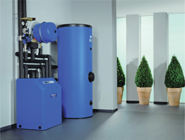
Figure 11.5 Heat pump installation. Source: Bosch Thermotechnik GmbH.
If sufficient space is not available in a garden, or there is no desire to dig up a whole plot of land, ground probes can be used to tap into the ground heat. Vertical boreholes can reach depths of 100 m. Constant temperatures of around +10 °C or more exist at these depths all year round. U-shaped pipe probes are inserted into the boreholes through which the brine of the heat pump will later flow. The depth of the drilling and the number of probes depend on the heat requirement and the composition of the ground below. Geologists and specialized drilling firms can help with the specifications. Depending on the composition of the ground at the bottom, the potential extraction capacity is between 20 and 100 W m−1. A rough estimate could be calculated at about 55 W m−1. Therefore, about 5.5 kW of refrigerating capacity could be extracted from a 100 m deep probe. In order to achieve a higher output several parallel probes with a distance of at least 5–6 m between them would be necessary.
In addition to the ground heat, heat from groundwater can be used. This requires a production well and a reinjection well. The reinjection well transfers the cooled groundwater back into the ground. It should be sited at least 10–15 m downstream of the production well, in the direction of the groundwater flow, so that the cooled water does not flow back to the supply bore (Figure 11.6).
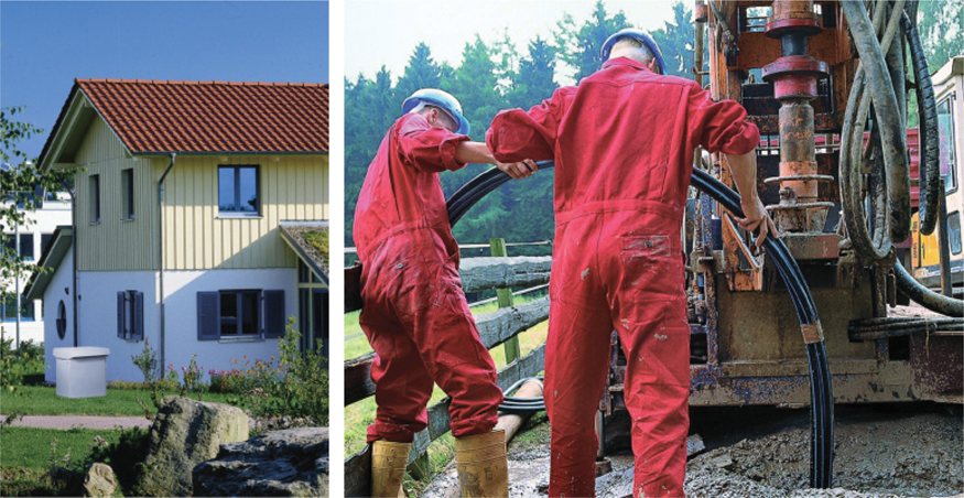
Figure 11.6 Air/water heat pump installed outdoors, without the need for drilling (left). Deep drilling for a water/water heat pump (right). Photos: STIEBEL ELTRON.
In many countries, approval must be obtained from the responsible water authority before groundwater can be extracted. This approval is usually given under certain conditions, except in groundwater protection areas. Permission is also often required to drill the ground probes for closed brine/water systems. In Germany, this is issued by the local water authority for drilling depths of up to 100 m. For deeper boreholes, an additional permit from the responsible mining authority is required. Normally, the drilling company applies for the required approvals.
From the Idea of a Heat Pump to Owning One's Own System
-
Determine possible heat sources:
Ground probe – Does deep drilling require approval?
Ground collector – Can a large section of the garden be dug up?
Groundwater – Is the house located in a groundwater protection area?
Air – Suboptimal solution if no other sources are available
- Calculate heat demand and heating capacity.
Can insulation help to reduce the heat demand?
Can the required temperatures be reduced through underfloor heating or larger radiators?
Request quotations for heat pumps and, if necessary, for the drilling.
Tip: Only hydrofluorocarbons (HFC)-free heat pumps should be used for climate protection reasons.
- If necessary, have the drilling company obtain approval for drilling.
Determine optimal energy tariff, and, if necessary, plan to have a buffer storage unit.
Tip: Choose a ‘green electricity’ option for climate protection reasons.
A photovoltaic (PV) system can cover part of the electricity demand at low cost.
- Examine favourable financing options in the context of wider climate protection measures.
- Arrange for the system to be installed by a qualified company.
11.4 Economics
Investment costs for a typical heat pump installation in a single-family home are between €8000 and €12 000. Added to this are the costs of tapping into a heat source, which are in the order of €3000–6000 for ground collectors or ground probes.
The costs of conventional heating systems are not applicable to new buildings with heat pumps. For example, with gas heating, the costs can include a gas connection and a chimney in addition to the gas boiler. Nevertheless, the investment costs for heat pump systems are usually considerably higher than for conventional gas or oil heating.
In Germany, between 2000 and 2013 heat pumps enjoyed economic advantages but these subsequently stagnated due to sharp increases in mains electricity costs. In particular, the sharp drop in oil prices after 2013 made it more difficult for heat pumps to compete (Figure 11.7). While domestic electricity is heavily burdened with taxes, taxes on heating oil and natural gas are comparatively low, although both energy sources have to be imported and are also questionable from an environmental perspective. It is to be hoped that legislation will intervene and improve the economy of the heat pump at the expense of climate-damaging oil and gas heating.
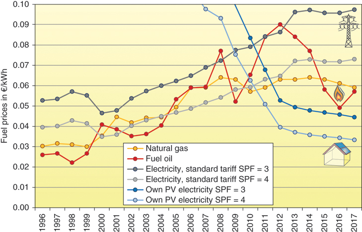
Figure 11.7 Development of domestic prices for gas, oil, and electricity for the operation of heat pumps for different seasonal performance factors (SPF) in Germany.
Due to the enormous cost reductions for PV systems over recent years, the operation of a heat pump with electricity from one's own PV system has been the most cost-effective way of supplying heat since 2012. However, in Germany it is generally not possible to cover the entire heat demand with PV electricity, due to the low solar radiation supply in winter, so in practice there will be a mixed calculation based on expensive grid electricity and low-cost PV electricity. With efficient heat pumps with SPF values of more than 3, in many cases the operating costs are lower than those of oil and gas heating systems. In contrast to the strongly fluctuating oil prices, the combination of a heat pump with a PV system ensures that the heat prices remain stable in the long term.
For large PV systems with a capacity of 10 kW or more, which can be achieved with a PV surface area of 60 m2 or more, German lawmakers have imposed an additional tax on self-consumption of climate-friendly solar electricity since 2014. This further worsens the economy of heat pump systems power from PV electricity compared to oil and gas heating.
If the heat pump is part of a modernisation measure or contributes to achieving the low-energy house standard, it may be possible to obtain low-interest loans through the German KfW Bank. The Federal Office of Economics and Export Control (BAFA) also promotes the installation of efficient heat pumps.
![]()
|
Comparison of heating costs in new buildings KfW Bank BAFA funding |
11.5 Ecology
Heat pumps are generally associated with a positive effect on the environment. But this is not always the case. The Achilles heel of heat pumps is the refrigerant. The range of refrigerants for compression heat pumps is broad. Chlorofluorocarbons (CFCs) were often used during the first heat pump boom. Because of their negative impact on the ozone layer, their use has been banned in new systems.
Today HFC, often called CFC equivalent substitutes, are mostly used. Although they are harmless to the ozone layer, they share another characteristic with CFC that is negative for the environment: both materials have extremely high greenhouse potential. As a result, even small quantities of between 1 and 3 kg of refrigerant in heat pumps for single-family homes are developing into an ecological problem. That is why the EU has restricted the use of climate-damaging refrigerants, with long transitional periods.
If 2 kg of HFC R404A reaches the atmosphere, it develops the same effect on the climate there as 6.5 tons of carbon dioxide. This quantity of carbon dioxide is emitted during the burning of 32 kW h of natural gas. The same amount heats a standard new-build house for three years and a 3-l house for an impressive nine years. The electricity demand of the heat pump itself is not even included in this balance sheet.
If a leakage occurs in a heat pump system, the refrigerants escape quickly because they evaporate under normal environmental conditions. On the positive side, HFC substances are neither toxic nor inflammable. However, in terms of climate-compatibility, the fast volatility of refrigerants turns out to be a problem. Not every heat pump will develop a problem whereby its entire content of refrigerant escapes into the atmosphere. However, refrigerant loss is unavoidable during the filling and disposal of a system and, due to continuous seepage, during regular operation. Nowadays standard heat pump suppliers seldom use refrigerants that can adversely affect the climate. At the same time heat pumps with R290 or propane as the refrigerant are not showing performance data that is any worse that those with refrigerants containing HFC. Special safety measures must be taken due to the flammability of refrigerants R290, R600a, and R1234, but for the most part these are easy to implement. In the past, more pressure to use HFC-free refrigerants was obviously placed on the manufacturers of refrigerators and freezers than on those of heat pumps. As a result, in Europe refrigerants that are not harmful to the environment have become part of the standard range in this area for years, despite their flammability.
In contrast, the HFC problem with heat pumps is still hardly ever discussed. Most manufacturers publicize the HFC they use as being environmentally friendly. One manufacturer is even brazenly claiming on their website that the refrigerant R407C is HFC-free. The layperson will find it almost impossible to distinguish between appliances and devices that contain HFC and those that are HFC-free. Table 11.3 provides some further guidance in this area, while HFCs are still permitted as refrigerants.
Table 11.3 Greenhouse potential of different refrigerants relative to carbon dioxide
| Abbrev. | Name | Material group | Greenhouse potential |
| R12 | Dichlordifluormethane | CFC | 6640 |
| R134a | 1,1,1,2-Tetrafluorethane | HFC | 1300 |
| R404A | Mixture of different HFCs | HFC | 3260 |
| R407C | Mixture of different HFCs | HFC | 1530 |
| R410A | Mixture of different HFCs | HFC | 1730 |
| R290 | Propane | HFC-free | 3 |
| R600a | Butane | HFC-free | 3 |
| R744 | Carbon dioxide | HFC-free | 1 |
| R717 | Ammonia | HFC-free | 0 |
| R1234yf | 2,3,3,3-tetrafluoropropene | HFC-free | 4 |
| R1270 | Propene | HFC-free | 3 |
Suppliers of heating systems often list heat pumps in the ‘renewable energy’ category. But this is only correct up to a point. Although most of the useable energy of a heat pump is in the form of renewable low-temperature heat from the environment, the power almost always comes from an electrical socket. This power is delivered by regular energy suppliers that frequently offer special tariff conditions because of the high quantity of electricity purchased for heat pump systems. In many countries this electricity ends up coming from coal-fired or nuclear power plants. In Norway, however, hydropower plants generate almost all the electricity used in the country. This makes the heat pump there a completely renewable system. Some countries offer the option of changing to green energy suppliers. Also, the heat pump can be powered at least partly by electricity from one's own PV system. In this case, too, a heat pump system is completely renewable and therefore free of direct carbon dioxide emissions.
If conventional electricity rather than green electricity is used to operate a heat pump, the savings in carbon dioxide emissions are significantly lower due to the poor efficiency of fossil thermal power plants compared to modern natural gas heating (Figure 11.8). If the heat pump also uses a HFC refrigerant that impacts the environment, in an extreme case the environmental balance can turn out to be even worse than with a modern heating system using natural gas.

Figure 11.8 Environmental balance of two heat pump heating options and natural gas heating.
11.6 Heat Pump Markets
After the first oil crisis in the 1970s, the heat pump sector experienced a real boom. However, due to technical problems, a drop in oil prices, and a lack of environmental compatibility, the market for heat pumps had collapsed almost completely by the late 1980s.
The market in Germany did not revive until the mid-1990s (Figure 11.9). However, heat pumps are much more popular in certain other countries than they are in Germany. Within the European Union, around one million heat pumps were installed in 2016. The markets in Sweden and Switzerland were significantly ahead of Germany. As the average carbon dioxide emissions resulting from the generation of electricity in Switzerland and Sweden are substantially lower than in Germany, heat pumps in those countries also have a much more favourable environmental balance. Heat pumps are currently used primarily in new residential buildings. Meanwhile, around 30% of all new buildings in Germany are heated with heat pumps.
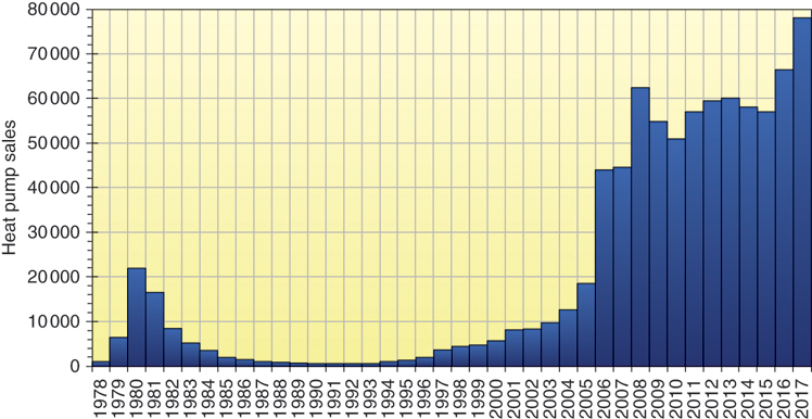
Figure 11.9 Sales of heat pumps in Germany.
11.7 Outlook and Development Potential
The environmental balance of heat pumps is improving continuously as a result of the steady increase in the share of renewable energies used to generate electricity. From an ecological perspective, the heat pump will become one of the most important alternatives to conventional heating systems once HFC-free alternatives start to replace refrigerants containing environmentally harmful HFC.
As renewable heating systems, such as solar thermal systems and biomass heating (see Chapter 12), can only cover a certain proportion of the heat demand in many countries, the heat pump is a key component of a carbon-free heat supply system. Buffer storage can also be used to change the operating times of heat pumps. This would enable heat pumps to be partially centrally controlled, thus helping to reduce service peaks in the electricity network. With a high availability of wind power, for example, heat pumps would fill heat storage tanks and then draw the heat again at times when power supplies were low. These possibilities indicate that a further expansion of the heat pump market can be expected.