CHAPTER 7
Solar Power Plants – Even More Power from the Sun
When we think of power plants, we usually imagine large central facilities with cooling towers and enormous chimneys emitting clouds of smoke. In terms of the concept itself, a power plant is merely a technical installation that converts a particular energy source into electricity. A solar power plant produces electric energy from solar radiation. We have already learned about one type of solar power plant – photovoltaic or PV systems. In principle, a small PV system sited on a single-family house does indeed constitute a solar power plant. However, since most people envisage a power plant as something much larger than a few square metres of solar modules, this chapter is devoted to large-scale systems that generate electricity from sunlight.
PV systems can in fact reach a size that is comparable with conventional power plants. Year after year new PV power plants have been breaking their own records in terms of size. PV systems with a capacity in the region of 5 MW and module areas of around 40 000 m2 have already been installed on the roofs of industrial buildings. However, existing roofs are usually not appropriate for even larger systems. Plants with 50, 100, or even 1000 MW can only be achieved with ground-mounted systems. Large PV plants are technically very similar to the small systems on single-family houses, except that they are larger in scale. This chapter therefore deals with other types of large-scale solar power plants.
Concentrators can be used to increase the intensity of solar radiation. PV cells with very high efficiency then convert the concentrated sunlight into electricity, as this chapter will explain. In addition to PV, other technologies for generating power from sunlight also exist. Solar thermal power plants convert solar radiation first into heat and then into electric energy. A number of different interesting and very promising technologies are available and are particularly suitable for the very sunny regions on Earth because they need direct sunlight, which is far less abundant in temperate climates such as those of Northern Europe.
7.1 Focusing on the Sun
Most of us remember as children trying to set fire to a sheet of paper or a piece of wood using a magnifying glass. Even this simple experiment makes us aware of the energy that concentrated solar radiation can produce. On Earth, sunlight can, in theory, be concentrated by a factor of 46 211 and reach temperatures of 5500 °C at a focal point. In practice, concentration factors of over 10 000 and temperatures of well over 1000 °C have been reached. Large holes can easily be melted into steel plates using concentrated solar radiation in solar ovens. Solar ovens are also suitable for testing materials at high temperatures. Figure 7.1 shows a solar furnace near Almería in Spain, which reaches an output of 60 kW with full sun radiation.

Figure 7.1 Solar furnace near Almería in Spain. Large tracking mirrors direct the sunlight towards a convex mirror (top right) in the interior of a building.
For cost reasons, glass lens systems are normally ruled out for use as concentrators in large-scale technical applications. The reflector, which concentrates sunlight onto a focal point or at the focus, normally has the form of a parabola. Due to their long useful life, glass mirrors have proven to be reliable in practical applications. The reflector must be tracked, so that the sunlight always comes in at a vertical angle. A distinction is mainly made between single-axis and dual-axis tracking systems. Single-axis tracking systems concentrate the sunlight onto an absorber pipe at the focus point, whereas dual-axis tracking systems concentrate it onto a central absorber close to the focal point. The tracking can occur either over a sensor, which catches the optimal orientation to the sun, or through a computer that calculates the sun's position.
 Archimedes – Inventor of the Concave Mirror?
The Greek scientist Archimedes of Syracuse, who was born in 285 BC, is considered the inventor of the concave mirror. Using concave mirrors, Archimedes is said to have set fire to enemy ships while his country was at war with Rome. The truth of this legend has been hotly debated for the last 300 years, but it is now considered unlikely. It would have taken very large and very precisely made mirrors, focusing on the ships over a very long period, to light the fires. Even if the legend is true, it did not do Archimedes much good. He was killed by the Romans when they captured Syracuse in 212 BCE.
Parabolic trough collectors, which concentrate sunlight onto an absorber pipe, are normally used as line concentrators (Figure 7.2 left). A Fresnel collector is one in which the concentrator is distributed over multiple mirrors, each individually lined up in an optimal position towards the absorber pipe (Figure 7.2 right).
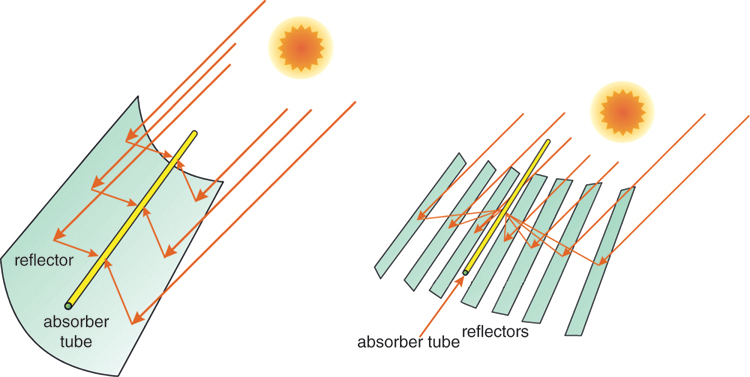
Figure 7.2 Single-axis tracking reflectors for line concentrators.
Concave mirrors are used for concentration onto a focal point (Figure 7.3 left). Distributed mirrors that are individually adjusted towards the sun can also concentrate the sun's radiation onto a central absorber (Figure 7.3 right).
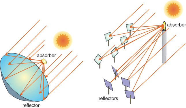
Figure 7.3 Dual-axis tracking reflectors for point concentrators.
7.2 Solar Power Plants
7.2.1 Parabolic Trough Power Plants
As the name indicates, in parabolic trough power plants large trough-shaped parabolic mirrors concentrate sunlight onto a focal point. The collectors are erected next to each other in a row several hundred metres long (Figure 7.4). Many parallel rows in turn form an entire solar collector field.
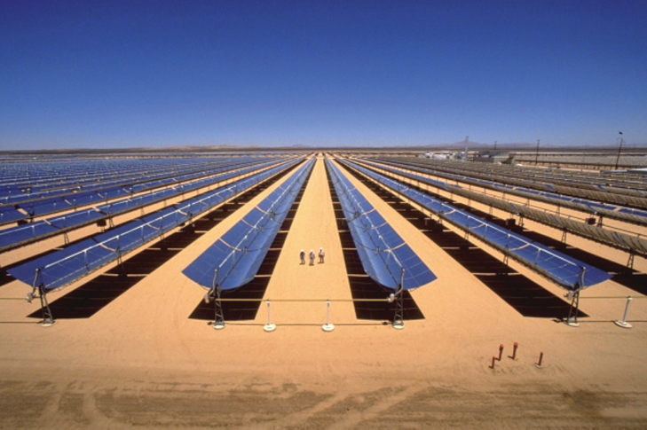
Figure 7.4 View of the Kramer Junction parabolic trough power plant in California (USA).
Photo: Gregory Kolb, SANDIA.
The individual collectors rotate on their longitudinal axis and in this way follow the course of the sun. The mirrors concentrate the sunlight more than 80-fold at the focal point onto an absorber pipe. This is embedded in an evacuated glass casing in order to reduce heat loss. A special selective coating on the absorber pipe reduces the heat radiated from the pipe surface. With conventional systems, a special thermal oil flows through the pipe, which heats up to temperatures of about 400 °C as a result of the solar radiation. The heat is transmitted over heat exchangers to a water-steam cycle, vaporized and overheated again. The steam drives a turbine and a generator, which produces electric power. Behind the turbine it condenses again into water and then returns to the cycle through a pump (Figure 7.5). The principle of producing electricity using steam turbines is called the Clausius-Rankine process, named after its inventors. This process is also used in classic steam power plants, such as coal-fired plants.
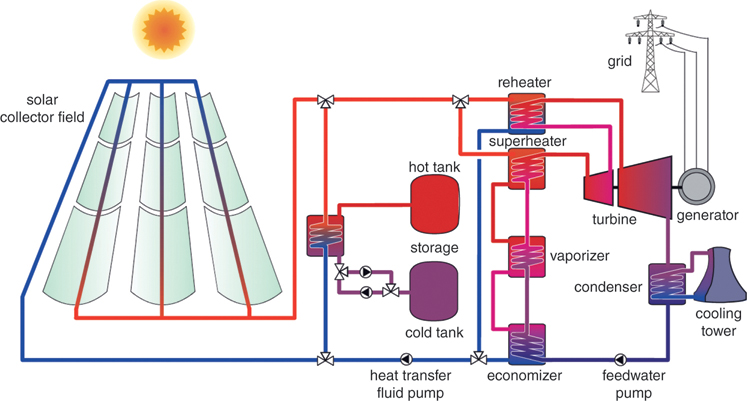
Figure 7.5 Parabolic trough power plant with thermal storage.
During periods of bad weather or at night a parallel burner can also be used to operate the water-steam cycle. In contrast to PV, this guarantees a daily output of power. It also increases the attractiveness of and planning security in the public electricity supply. For totally carbon-free plant operation, either biomass or renewably produced hydrogen can be used as a supplementary fuel, or the burner can be eliminated entirely. Instead a thermal storage tank can be integrated. The solar field heats up the storage during the day using excessive heat. At night and during periods of bad weather the storage feeds the water-steam cycle (Figure 7.6). The storage must be designed to handle temperatures above 300 °C. Molten salt is suitable as a storage medium at this temperature range.

Figure 7.6 Solar thermal power plants with thermal storage can provide guaranteed output around the clock.
The development of solar thermal parabolic trough power plants dates back to 1906. In the USA and near the Egyptian city of Cairo – at the time still under British rule – research facilities were set up and the first tests were successful. Based on appearance, these trough facilities were incredibly similar to those used today. However, problems with materials and other technical difficulties ended this first attempt at large-scale technical generation of solar electric power in 1914, shortly before the start of the First World War [Men98].
In 1978 the foundations were laid in the USA for a resurrection of this technology. The Public Utility Regulatory Policies Act obligated American public electricity companies to buy energy from independent producers at clearly defined costs. After the surge in energy costs in the wake of the oil crisis, the electricity provider Southern California Edison (SCE) offered long-term feed-in conditions. The introduction of favourable tax advantages finally made the construction of plants worthwhile financially. The LUZ Company, which was founded in 1979, negotiated a 30-year contract for the feed-in of solar energy with SCE in 1983. In 1984 the first solar thermal parabolic trough power plant was built in the Mojave Desert in California. By 1991, a total of nine SEGS power plants (Solar Electric Generation Systems) with 354 MW of electric output were installed in an area of more than 7 km2. These power plants feed around 800 million kilowatt hours into the grid each year, enough to satisfy the requirements of 60 000 Americans. Eight power plants can also be operated with fossil fuels, thus enabling them to supply electricity at night or during periods of bad weather. With these plants the annual natural gas portion of the thermal energy supplied is legally set at 25%. The total investment for the plants was more than US$1.2 billion.
In the mid-1980s energy prices fell dramatically again. Then the tax exemptions also ran out at the end of 1990, and the LUZ Company went bankrupt even before construction could start on their tenth power plant. A long lean patch then followed for the planners of solar thermal power plants. It lasted until 2006, when building work was started on new parabolic trough plants in Nevada in the USA and near Guadix in Spain. Today, there are a number of new trough power plants in various countries.
Technical advances made in the meantime have helped to increase efficiency and reduce costs. One option was the use of direct solar steam. With this process water is vaporized at a high pressure by the collectors and heated up to 500 °C. This steam is led directly into a turbine, thereby rendering thermo oil and heat exchangers superfluous.
Temperature and Efficiency
The Achilles heel of solar thermal power plants is not the solar collector that concentrates the sunlight. Collectors easily achieve efficiency of over 70%. However, most of the valuable solar heat is lost during its conversion into electricity. The steam turbines used in this process in solar power plants barely manage to achieve 35% efficiency. In other words, 65% of the heat gained from the sun returns unused as waste heat into the environment.
The efficiency of steam turbines results directly from the temperature difference of the steam between entry into and exit from the turbines. The exit temperature depends on the cooling and even at best is only minimally below the ambient temperature. With parabolic trough power plants, the entry temperature, contingent on the thermo oil, is currently just below 400 °C. With a temperature increase to 500 °C or higher, the efficiency of turbines could easily reach 40%. But this is the maximum even for steam turbines. Combined cycle gas turbine plants (CCGT), which operate at temperatures of over 1000 °C, achieve efficiency of up to 60%. CCGTs with high efficiency can be used, for example, in solar tower power plants.
One question that is often asked is whether simple pipe collectors can be used to generate electricity from general purpose water. In principle, this would be possible. However, due to the extremely low temperatures, efficiency would be too minimal to make this approach economically viable. Even the waste heat in the environment would have limited use. Solar power plants are normally situated in hot, sunny regions. However, a demand for gigantic quantities of low-temperature heat does not really exist in these areas.
7.2.2 Solar Tower Power Plants
In solar tower power plants, hundreds or even thousands of rotating mirrors are arranged around a tower. Called heliostats, these mirrors are individually controlled by computer to track the movement of the sun and are orientated towards the top of the tower. They must be orientated precisely within a fraction of a degree, so that the reflected sunlight actually reaches the focal point. A receiver is located here with an absorber, which, due to the highly concentrated sunlight, heats up to temperatures of over 1000 °C. Air or molten salt transports the heat. A gas or steam turbine that drives a generator ultimately converts the heat into electric energy.
The tower uses open volumetric receivers (Figure 7.7), where ambient air is sucked by a fan through a receiver towards which the heliostats are orientated. The materials used for the receiver are wire mesh, ceramic foam, or metallic or ceramic honeycomb structures. The receiver is heated up by the solar radiation and transfers the heat to the sucked-through ambient air. The sucked-in air cools the front side of the receiver. Very high temperatures only develop on the inside of the receiver. This volumetric effect reduces radiant heat losses. The air, which is heated to temperatures between 650 and 850 °C, enters a waste heat boiler that vaporizes and overheats the water, thereby driving a steam turbine cycle. If required, this type of power plant can be fired by a channel burner using other fuels.
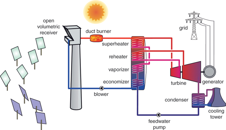
Figure 7.7 Solar tower power plant with open air receiver.
A more advanced version of the tower concept that uses a pressure receiver is now offering promising possibilities for the future (Figure 7.8). With this concept, the concentrated sunlight heats the air to temperatures up to 1100 °C in a volumetric pressure receiver at about 15 bars. A transparent quartz-glass dome separates the absorber from the environment. The hot air then drives a gas turbine. The waste heat of the turbine then finally drives the downstream steam turbine process. The first prototype has shown that this technology functions successfully.
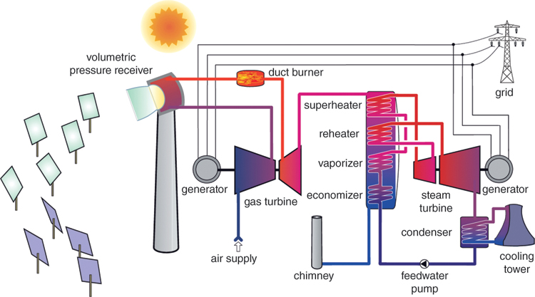
Figure 7.8 Solar tower power plant with pressurized air receiver.
With the combined gas and steam turbine process the efficiency of the conversion from heat to electric energy can be increased from about 35% to more than 50% with a pure steam turbine process. As a result, total efficiencies of more than 20% are possible with this type of conversion of solar radiation into electricity. These prospects justify the additional complexity and cost of receiver technology.
In contrast to parabolic trough power plants, there has not been much experience with commercial plants in the solar tower plant area. Research facilities that are optimizing system components and testing new components currently exist in Almería (Spain) (see Figure 7.9), Daggett (USA) and Rehovot (Israel).
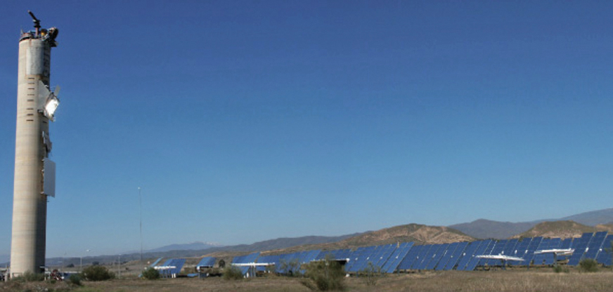
Figure 7.9 Research site for a solar tower power plant at Plataforma Solar de Almería (Spain).
The first commercial solar tower power plant to be put into operation was the 11-MW PS10 tower plant near Seville in Spain in 2006. However, instead of heating up air, the receiver of this plant vaporizes water. Due to the low temperatures it achieves, the efficiency of this power plant is still relatively low. In 2009, the 20 MW PS20 solar tower plant was completed near Sevilla. Several solar tower plants were planned and built in the USA. In contrast to the air-based concepts described above, these mostly use liquid salt as the heat transfer medium.
Before it can be launched successfully in the market, the open-air receiver technology developed in Germany first has to prove its suitability for practical use. This is currently being tested at a newly built solar tower plant in Jülich, Germany. With 1.5 MW of power this demonstration plant is considerably smaller than the commercial Spanish plants. The target in this effort is not the German power plant market but to promote the export of German technology to the sunny countries of the world.
7.2.3 Dish-Stirling Power Plants
Whereas trough and tower power plants are only economically viable in large-scale applications of many megawatts, the so-called Dish-Stirling systems can also be used in smaller units – for example, to supply remote villages or towns. With Dish-Stirling systems a convex mirror in the form of a large dish concentrates the light onto a focal point. To ensure that the light is concentrated as strongly as possible, the mirror is dual-axis tracked very precisely towards the sun.
A receiver is sited at the focal point. This receiver transfers the heat to the actual heart of the system: the Stirling hot gas engine. This engine converts the heat into kinetic energy and drives a generator that ultimately produces electric energy.
A Stirling engine can be driven not only by the heat of the sun but also through combustion heat. In combination with a biogas burner these plants can also generate electricity at night or during periods of bad weather. And the use of biogas also makes them carbon-neutral.
Some prototypes of pure solar systems have been built in Saudi Arabia, the USA, and Spain (Figure 7.10). Compared to tower and trough power plants, the price per kilowatt hour with Dish-Stirling systems is still relatively high.

Figure 7.10 Prototype of a 10-kW Dish-Stirling system near Almería in Spain.
7.2.4 Solar Chimney Power Plants
There is a big difference between solar chimney power plants and the thermal plants described earlier. While solar thermal power plants work by concentrating sunlight, solar chimney power plants function through the heating of air. The collector field is formed by a large flat area that is covered by a glass or plastic roof. A high chimney is located in the middle of the area, and the collector roof rises gently in the direction of the chimney. The air is able to flow in unencumbered at the sides of the enormous roof. The sun warms the air under the glass roof. This air then rises upward, follows the gentle slope of the roof and then flows at great speed through the chimney. The airflow in the chimney then drives wind turbines that generate electric power over a generator.
The ground under the glass roof can store heat, so that the power plant is still able to deliver power even after the sun has set. If hoses filled with water are laid in the ground, enough heat can be stored to enable the plant to provide electric power around the clock.
At the beginning of the 1980s a small demonstration plant with a rated power output of 50 kW was built near Manzanares in Spain. The collector roof of this plant had an average diameter of 122 m and an average height of 1.85 m. The chimney was 195 m high and had a diameter of 5 m. This plant was dismantled in 1988 after a storm knocked the chimney down. However, all the planned tests had been completed and the research plant lived up to expectations. It was the first successful demonstration of a solar chimney power plant.
Because the efficiency of solar chimney plants compared to other techniques is very low, these plants require large areas of land. Furthermore, the efficiency increases in line with the height of the tower, therefore, to be economically viable, plants must be of a certain minimum size. Similar power plant projects have been under discussion in Australia, for example. Consideration is being given to a large-scale 200 MW plant with a tower height of 1000 m, a tower diameter of 180 m and a collector diameter of 6000 m but so far, however, all projects have failed in the end due to funding issues (Figure 7.11).
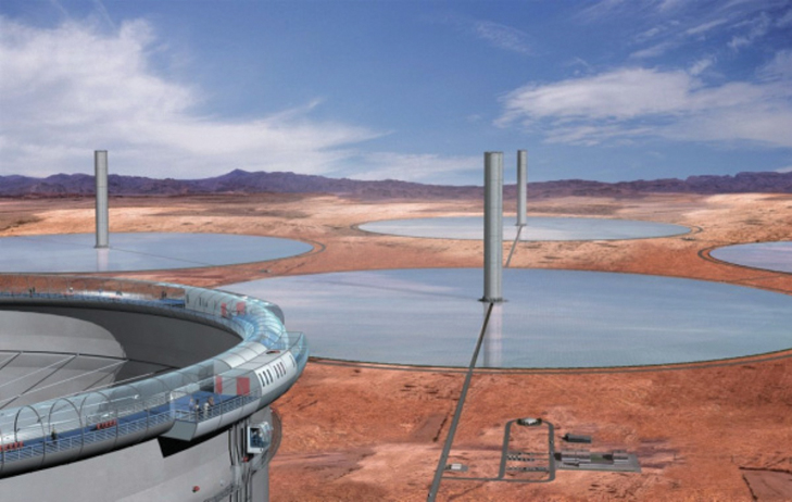
Figure 7.11 Computer animation of a solar chimney power plant park. The towers can also be used as viewing platforms.
Image: Schlaich Bergermann Solar, Stuttgart.
7.2.5 Concentrating Photovoltaic Power Plants
PV cells can also be operated by concentrating sunlight. The main point of this is that the concentration saves on valuable solar cell material. If sunlight is concentrated by a factor of 500, the size of the solar cell can then also be reduced by a factor of 500. The cost of the solar cell therefore becomes much less of an issue. This means materials that ordinarily would be too expensive without solar concentration could also be used. Concentrator cells, therefore, usually have higher efficiency than conventional PV modules.
There are many options for the concentration: for example, concentrator cells can be mounted at the focal point of parabolic troughs or convex mirrors. One of the main problems with this is efficient cooling, because, in addition to the electric energy of the solar cells, a large quantity of waste heat is produced. Flatcon technology takes a different approach. A flat Fresnel lens concentrates the sunlight onto a concentrator cell that is only a few square millimetres in size (Figure 7.12 below right). A copper plate on the back of the cell radiates the heat that accumulates extensively towards the back. A concentrator module comprises a large number of parallel cells. Many modules are then mounted together on a tracking device that orientates the modules optimally towards the sunlight.

Figure 7.12 PV power plant with concentrator cells.
Photo/graphics: Concentrix Solar GmbH.
7.2.6 Solar Chemistry
In addition to providing process heat or generating electricity, concentrating solar thermal energy can also be used for testing materials or in solar-chemical systems. For instance, there is a large solar furnace in the French town of Odeillo, where a large number of small mirrors are mounted on a hillside. These mirrors reflect the sunlight to a concave mirror 54 m in diameter, creating temperatures of 4000 °C in the solar furnace, which is used for research and industrial processes. Solar furnaces have also been built in Almería, Spain, and Cologne, Germany.
In addition to producing chemicals at high temperatures, solar thermal energy can also be used to produce hydrogen. This does not require a circuitous route that starts with generating electricity, followed by electrolysis. At high temperatures hydrogen can be produced through a solar-chemical process. For example, the chemical system could be in the receiver of a solar tower. Hydrogen is treated as an important energy source, particularly in the transportation sector and in fuel cells. If a hydrogen economy ever becomes a reality, concentrating solar-chemical systems could play a major role in hydrogen production.
7.3 Planning and Design
Solar thermal power plants are usually similar to typical large conventional thermal power plants. Due to their size, they cost millions of euros. Solar plants are almost always planned and built by large corporations or industrial companies. The design of these plants is usually very complex. It takes teams of engineers a long time to complete the detailed planning. One of the main goals is to optimize power plants from an economic perspective.
Private individuals are not likely to have any involvement in the planning of solar power plants, unlike the situation with small PV systems and solar thermal systems that heat tap water or provide auxiliary heating. However, the rise in the number of solar power plants is presenting many opportunities for investment in this area. Therefore, it is worth taking a quick look at the planning aspects.
Because concentrating solar power plants suffer a major reduction in efficiency in the partial load area, the aim should be to build them mainly in countries where there is a lot of sunshine. The regions currently of interest are those with an annual total global radiation of at least 1800 kWh m−2. The optimal values are clearly those over 2000 kWh m−2. These areas appear in red or pink in Figure 7.13.

Figure 7.13 World map with annual totals for solar global radiation in kWh/m2.
Source: Meteotest, www.meteonorm.com.
7.3.1 Concentrating Solar Thermal Power Plants
Concentrating solar power plants can only utilize the direct irradiance portion of the sun. This portion of irradiance can be reflected by mirrors to be ultimately concentrated. The global irradiation intensity, i.e. the sum of direct and non-directional diffuse sunlight, is important for non-concentrating solar systems. The efficiency of these systems is therefore related to the global irradiation intensity. With concentrating systems, the direct-normal radiation intensity on a surface orientated vertically towards the sun serves as a reference quantity (see Figure 7.14). In the technical jargon this is abbreviated to DNI, which stands for ‘direct normal irradiance’. The DNI values can lie somewhat below but also somewhat above the values for global radiation.
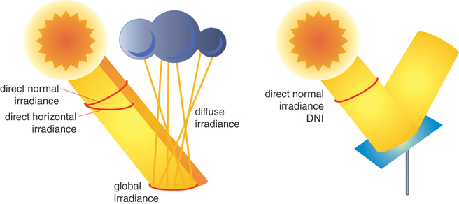
Figure 7.14 Differentiation of types of solar radiation.
 Annual Electricity Production of Solar Power Plants
The annual output yield of a concentrating solar thermal system can be estimated using the average efficiency, the annual total of solar direct-normal irradiance DNI, and the aperture area A of the mirrors:
With an efficiency | of 15% = 0.15, a solar thermal parabolic trough system with an overall aperture area of 500 000 m2 at a Spanish location and a DNI of 2200 kWh (m2 a)−1 achieves an annual yield of:
This is sufficient to cover the electricity needs of around 50 000 Spanish households.
Another interesting aspect of planning is how the land is used. So, that the mirrors do not throw shadows on one another, they can only be installed on about one-third of the available land area. The land area for a concentrating solar power plant must therefore be at least three times bigger than the surface area of the mirrors.
The mirror area should be coordinated optimally with the rest of the plant. If it is too small, the plant will constantly be running in partial-load operation. As a result, both efficiency and yield will drop. If the size of the mirror area is too large, a higher amount of solar radiation will fall onto the collectors than can ultimately be converted into electricity. In this case some of the mirrors have to be turned away from the sun.
The efficiency depends on the technology used. Dish-Stirling power plants and solar tower plants with pressure receivers can reach efficiencies of 20% or more. Solar tower or trough plants with steam turbines are currently at about 15% efficiency. An increase in DNI irradiance values also increases efficiency as a power plant will then be running for shorter periods in partial-load operation. In Germany, efficiency in the order of 10% is all that can be expected from its solar thermal power plants – and this is based on moderate DNI irradiance values of about 1000 kWh m−2 and by year. The annual yield from concentrating solar power plants in places like Spain would be roughly three times higher than in Germany or Great Britain.
7.3.2 Solar Chimney Power Plants
With solar chimney power plants, the annual yield is calculated on an analogous basis. Instead of the DNI, the global radiation is used because these plants can also use diffuse sunlight. The total efficiency is only about 1% – and then only if the tower is more than 1000 m high. Thus, the efficiency of a solar chimney power plant is directly correlated to the height of the tower. At half the optimal tower height the efficiency is also halved. The collector area would have to be doubled in size to achieve the same yield. In contrast to a concentrating power plant, a solar chimney plant can use the entire land area. No unused gaps are necessary to prevent shading.
7.3.3 Concentrating Photovoltaic Power Plants
The annual yield from concentrating PV power plants is also calculated analogously. Compared to non-concentrating PV plants, an efficiency of more than 20% is possible. As concentrating PV plants can only use the direct-normal irradiance portion, the yield in sunny countries rises disproportionally.
7.4 Economics
Until a few years ago, solar thermal power plants were able to produce electricity much more cost-effectively than PV systems. Due to the strong cost reductions in PV, this advantage no longer exists today. In Germany, an economically viable operation of solar thermal power plants is practically impossible (Figure 7.15).

Figure 7.15 Solar thermal power plants (left) can achieve economic advantages over PV (right) when storage tanks are required for high reliability.
The main advantage of solar thermal systems is the simple integration of thermal storage. Small storage units used for a few hours only minimally increase the cost of generating electricity at solar thermal plants. However, they ensure that the power output of the plants can be guaranteed and, as a result, increase the availability and the value of electric energy. In solar thermal power plants, storage can generally be integrated much more cheaply than in PV. As a result, solar thermal power plants in very sunny countries are certainly of economic interest if high reliability is to be achieved through thermal storage.
In Spain, the cost of generating electricity from parabolic trough and solar tower power plants in 2012 was around 20 cents kWh−1; at the top locations in North Africa the cost was about 15 cents kWh−1. As with PV, an increase in installed capacity of solar thermal power plants is expected to result in significant cost reductions. Costs have already been significantly reduced by the construction of a number of new solar trough and tower power plants. Meanwhile, the costs for new plants are in the range of 10 cents kWh−1. In the future, costs in the order of 5 cents kWh−1 seem achievable.
In the case of solar chimney and Dish-Stirling power plants, there are no signs yet of a comparable rapid market development. Different studies show that these plants also have the potential to be competitive in electricity generation in the long term. However, it remains to be seen whether they can meet these expectations.
In the case of concentrating PV, electricity generation costs at locations with high solar radiation are also expected to be similar to those of conventional PV systems. Various suppliers have developed interesting systems in recent years. However, due to the strong cost pressure of standard PV, most suppliers of concentrating systems had to discontinue their activities.
The advantage of PV systems compared to solar thermal systems is modularity. PV systems can be built in any required size – ranging from milliwatts all the way to multi-megawatt plants several square kilometres in area. Solar thermal power plants are always dictated by the minimum output that is needed to make the plant economically viable. With Dish-Stirling power plants, this is around 10 kW. All other solar thermal power plants should have a minimum output of 10 MW. Efficiency is increased even further if output levels are between 50 and 200 MW. Optimally, a system should be 1 km2 or more in total size to make it economically viable.
7.5 Ecology
Solar power plants without fossil fuel backup facilities do not release any direct carbon dioxide emissions during operation. When a fossil fuel-fired parallel burner exists, as is the case with some solar thermal parabolic trough power plants, the natural gas portion should be kept to an absolute minimum. Due to the low temperatures, the efficiency of solar thermal plants for electricity generation is lower than that of optimized pure natural gas plants. This aspect is insignificant when power plants are run purely on solar power. However, if fossil fuels are burnt as well, the carbon dioxide emissions rise. It is accepted that the addition of fossil fuels will increase supply reliability and protect against frost. But the fossil portion should not exceed 10% to ensure effective environmental protection.
Some World Bank projects in developing countries are striving towards an integration of relatively small parabolic trough collector fields into conventional gas and steam power plants run on natural gas. Due to technical restrictions, the solar portion is clearly below 10% there. This type of ISCCS (Integrated Solar Combined-Cycle System) is not suitable for effective climate protection.
The production energy required for thermal solar power plants is lower than that of conventional PV systems. Within a year a solar power plant will deliver more energy than was originally used to produce the plant.
Unlike small PV and solar thermal systems, solar systems cannot be integrated into buildings. Instead they need large open areas of space comprising many hectares. Ideally, solar plants should be erected in thinly populated areas where the land is not needed for other purposes. Fortunately, many sunny regions on Earth have just these characteristics. Very little grows in hot deserts where the sun shines almost all year round, and the human populations tend to be low. Solar thermal power plants built on suitable desert sites would easily be able to meet the electricity demands of the entire planet a hundred times over.
The main problem with thermal systems is the need for cooling water. Water is often a scarce resource in sunny regions. The small number of power plants installed until now have always been able to find local water reserves for cooling. On a larger scale, freshwater cooling in regions with little water is a problem. In principle, a solar thermal power plant can also operate with dry cooling. In this case, efficiency drops a little and the costs increase slightly. On a long-term basis, solar thermal power plants with dry cooling should also become economically interesting enough to resolve the water-cooling issue. If solar thermal plants are installed near the sea, the water from the sea can provide effective cooling. The waste heat of solar thermal facilities can also be used to desalinate sea water. It should be possible to produce carbon-free electric energy and drinking water at the same time, but until now this has not been done on a large scale.
7.6 Solar Power Plant Markets
The biggest markets for solar power plants exist in countries that have good solar radiation conditions and offer favourable energy credits. The largest installed solar power plant capacity is currently in Spain and the USA.
This is mainly due to the local economic conditions. Energy credits for solar thermal power plants in Spain are high and above the typical market prices for electric energy. The USA uses Renewable Portfolio Standards (RPSs). These vary from state to state and establish quotas for renewable energy plants. Plants are being built or planned in certain US states such as California and Nevada. Other sunny and hot US states could follow suit.
![]()
| Information on solar thermal power plant projects |
In the meantime, there are also larger solar power plants in Morocco, India, South Africa, Egypt, Mexico, and the United Arab Emirates. Further projects are underway in China, Australia, and Chile, among other countries. All large solar power plant projects are trough or tower power plants.
In Germany the focus has been mainly on developing the appropriate technology. Germany has been among the market leaders in the world, specifically in the area of components for solar thermal parabolic trough power plants. A prototype for a solar tower power plant, built in 2008 in Jülich, aims to showcase German technology and attract new export markets (Figure 7.16).
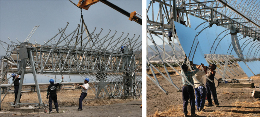
Figure 7.16 Construction of a parabolic trough collector prototype in Andalusia. Spain is currently one of the largest markets for solar power plants alongside the USA.
7.7 Outlook and Development Potential
Although the expansion in solar thermal power plants came to a standstill between 1991 and 2006, a few new facilities are now either at the planning stage or under construction. The current renaissance in the area of solar thermal power plants is likely to lead to further cost reductions. The main competitor of solar thermal power plants is PV, which is now much cheaper. At present, solar thermal power plants still have cost advantages in situations where storage is to be integrated. But there are also rapid cost reductions in PV systems with batteries. At the moment, therefore, it is not clear which technology will prevail in sunny countries when it comes to reliable electricity production with the aid of storage facilities.
There is enormous potential for the construction of solar power plants in North Africa. Even with a generous exclusion of unsuitable areas, such as sand dunes, nature reserves and mountainous and agricultural regions, about 1% of the remaining area of North Africa would theoretically be able to produce enough electricity to meet the demands of every country on Earth. Figure 7.17 shows the areas available there.
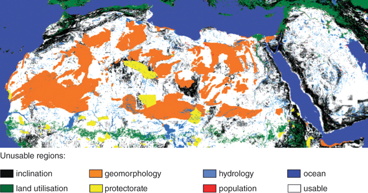
Figure 7.17 Suitability of different regions in North Africa for building solar power plants. Suitable areas shown in white. Unsuitable areas colour-coded.
Graphics: DLR.
The question is, how can reasonably priced electricity from Egypt or Mauretania help us to solve our energy problems? The solution to this problem is simple. The cheap electricity would merely have to be transported to us. Figure 7.18 shows the top locations for obtaining this electricity and the possible transport routes to Europe.
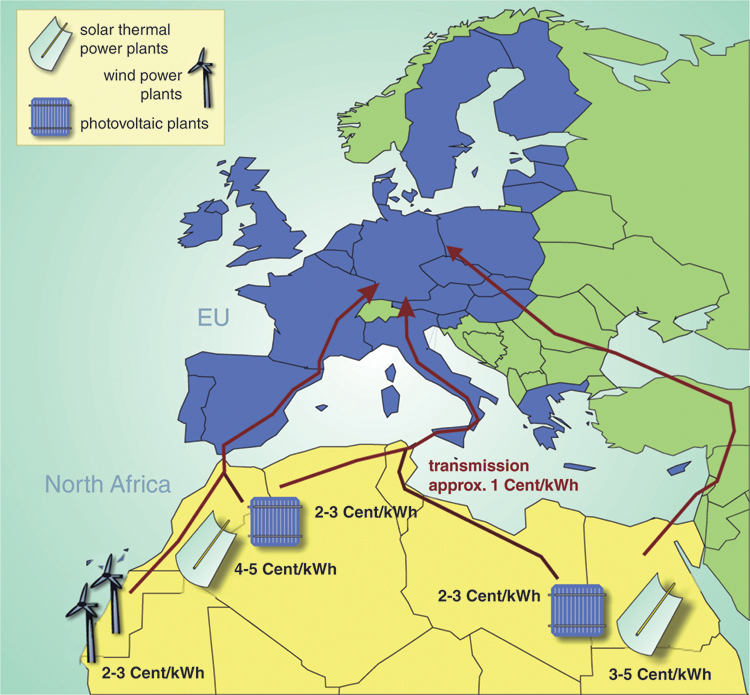
Figure 7.18 Options for renewable electricity imports from North Africa to the EU and electricity generation costs feasible in the medium term.
Technically as well as financially, the transport of this energy is already viable today through high-voltage-direct-current transmission (HVDC). Transmission over a 5000 km long HVDC cable with losses of less than 15% is possible. These losses amount to around 0.5 cents kWh−1, based on the possible electricity generation costs of 2–3 cents kWh−1 for PV and around 5 cents kWh−1 for solar thermal power plants. Added to this is the cost of the lines, which works out to between 0.5 and 1 cent kWh−1. Altogether renewable energy could be produced at 3–6 cents kWh−1, transported to Europe and, in combination with PV, wind or solar thermal power plants and integrated storage, guarantee high supply reliability.
This concept became known some time ago under the name DESERTEC and was promoted in 2009 with the participation of large corporations. In the meantime, many companies have since withdrawn. The Achilles' heel of the concept is the construction of long transmission lines, which is causing resistance in Germany and elsewhere, and the rather uncertain political situation in some North African countries.
Independently of the DESERTEC developments, some countries such as Morocco are in the process of establishing their own large solar power plant capacities. However, these primarily serve to cover the rapidly increasing electricity demand of their own country. If, in the future, solar power plant capacities reach dimensions where significant surpluses occur, they can certainly also be exported to southern European countries. The extent of new transmission lines required for this would be comparatively low. In the meantime, the costs for solar and wind power plants have fallen so sharply that they can also generate electricity in central Europe for well below 5 cents kWh−1. It therefore remains to be seen to what extent an electricity import from Africa will contribute to the supply of electricity in Germany and neighbouring countries in the medium or long term.