
CHAPTER 9
Hydropower Plants – Wet Electricity
Today there are far fewer hydroelectric plants than there were in their heyday at the end of the eighteenth century. At that time between 500 000 and 600 000 water mills were running in Europe alone [Köni99]. In those days France was the country with the highest number, although thousands were also being used in other parts of Europe. Water wheels not only drive mills but also power a number of other tools and machines. Flowing waterfalls were harnessed by watermills with wheels up to 18 m in diameter. At five to seven horsepower the average power of water mills at that time was still comparatively modest (Figure 9.1).
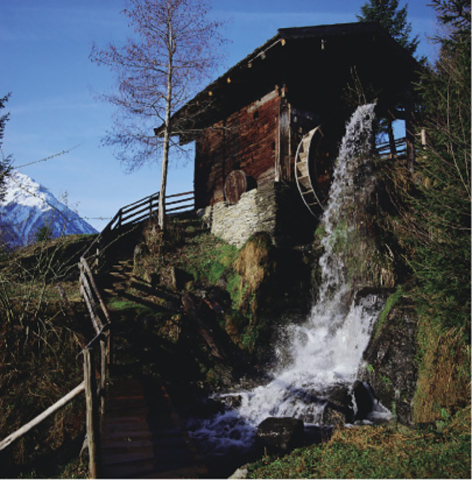
Figure 9.1 Historic watermill in the Alps. Source: Verbund, www.verbund.at.
As more and more mills were built on rivers and streams, the activity was strictly regulated, and mill operators were instructed on how long mills could be used and how large they could be. This may have been an annoyance for them, but it was a good thing because it promoted technical development and ensured that optimal use was made of existing mills. This constant drive to improve gave rise to the modern, highly efficient turbines used in hydropower plants today.
The introduction of the steam engine slowly displaced water-powered systems. But, in contrast to wind power, the use of hydropower did not vanish with the increased exploitation of fossil energies. When widespread electrification began at the end of the nineteenth century, hydropower was still very much part of the scene. At the beginning small turbines were used to power electric generators, but the size of the systems grew rapidly.
9.1 Tapping into the Water Cycle
The colour of our planet is blue when seen from space. The reason is that 71% of the Earth's surface is covered by water. However, without the sun our blue planet would not be blue. Water, which gives the Earth its characteristic appearance, would be completely solidified into ice, as 98% of water is liquid purely due to the sun's heat.
 A Water-Powered System in the Rain Gutter?
The roof of a house collects many cubic metres of water each year. A rain gutter diverts the water without making any use of its energy. A water powered system for each rain gutter could actually be a good idea.
The annual precipitation in Berlin amounts to around 600 l per square metre, so that a 100 m2 house roof would collect 60 000 l or 6000 10-l buckets of water. Compared with a similar bucket on the ground, the content of a 10-l bucket on a 10 m-high roof has a potential energy of 0.000273 kW h. Six thousand buckets together create around 1.6 kW h, just enough to boil water for 80 cups of coffee, but unfortunately too little to make it worthwhile to harness. Thus, considerably larger quantities of water than are available in a rain gutter are necessary to produce viable quantities of energy.
Altogether there are around 1.4 billion cubic kilometres of water on Earth. Of this amount, 97.5% is salt water in the oceans and only 2.6% is fresh water. Almost three-quarters of the fresh water is bound in polar ice, ocean ice, and glaciers; the rest is mainly in the groundwater and soil moisture. Only 0.02% of the water on Earth is in rivers and lakes.
Due to the influence of the sun, on average 980 l of water evaporate from each square metre of the Earth's surface and return elsewhere in the form of precipitation. Altogether about 500 000 cubic kilometres of water collect in this way each year. This gigantic water cycle converts around 22% of all the solar energy radiated onto Earth (Figure 9.2).
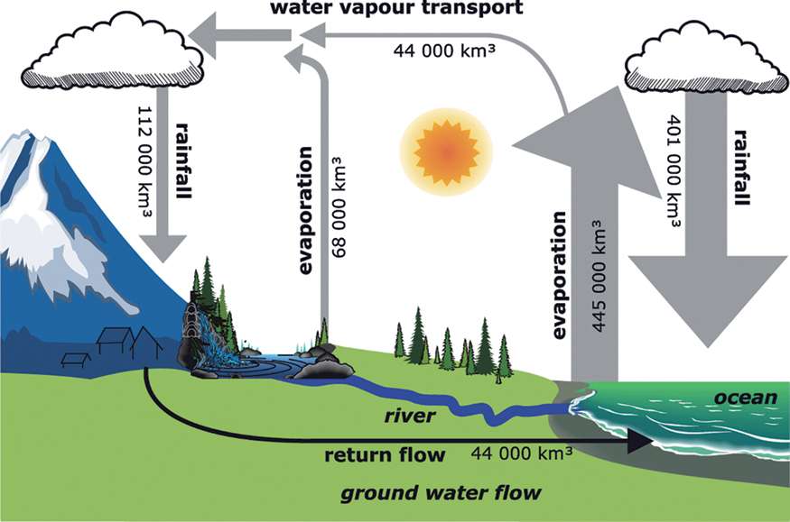
Figure 9.2 Earth's water cycle.
If the evaporation were concentrated onto a single square kilometre on Earth, the water would come pouring out at a speed of over 50 km h−1. The column of water would reach the moon in less than one year. Fortunately, however, the water remains spread on the surface of the Earth, because otherwise we would not have any liquid water left in 3000 years.
The energy that is converted by the sun in the Earth's water cycle is around 3000 times the primary energy demand on Earth. If we were to stretch a tarpaulin at a height of 100 m around the Earth, collect all the rainwater into it and use it to produce energy, we would be able to satisfy all the energy needs on Earth.
Altogether 80% of precipitation comes down over the ocean, while a large amount of the 20% falling on land evaporates. Around 44 000 cubic kilometres of water reach the ocean again as return flow in groundwater or in rivers. This is still more than one billion litres per second. We could be making use of the energy of the water from this return flow without stretching large tarpaulins over the Earth. This water could be delivering some of its energy on its way back to the ocean – energy that it first received from the sun. Yet the usable amount of energy that rivers carry with them comprises only a small fraction of the energy of the water cycle.
To convert water into power, it is not just the amount of water that is important but the height at which water is found. Water in a small mountain stream with many hundreds of metres of difference in elevation can sometimes carry more energy than a large river that only has to descend from an elevation of a few metres to reach the ocean. About a quarter of the energy of water from rivers and lakes can theoretically be used. This equates to around 10% of current global primary energy demand. Ocean currents and waves also contain usable energy.
9.2 Water Turbines
Water turbines form the core of water-powered systems and extract the energy from water. Modern water turbines have very little in common with the rotating wheels of traditional watermills. Depending on the head of the water and the water flow, turbines optimized for the respective operating area are used (Figure 9.3). These turbines reach a power of over 700 MW.
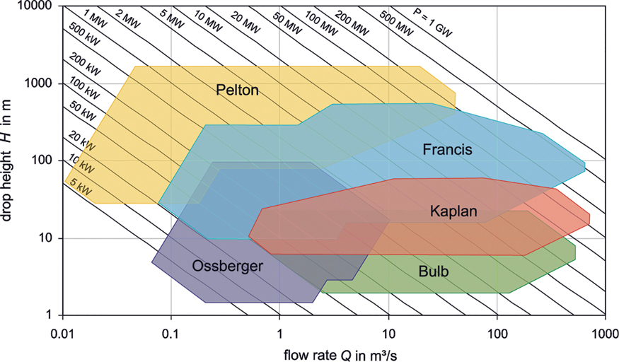
Figure 9.3 Applications for different water-powered turbines.
The Kaplan turbine, developed by the Austrian engineer Viktor Kaplan in 1912, is usually the first choice for low heads – for instance, for power plants on rivers (Figure 9.4). This turbine uses the pressure of the water at the different elevations of barrages. It has three to eight adjustable blades and looks like a large ship screw (propeller) that powers the flowing water. The efficiency of Kaplan turbines reaches values between 80% and 95%.
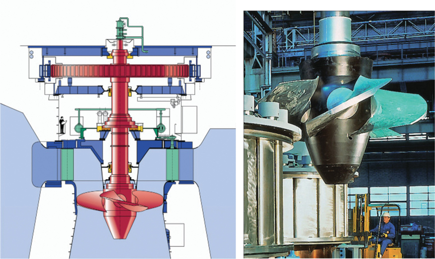
Figure 9.4 Drawing showing a Kaplan turbine with a generator (left) and a photo of a Kaplan turbine (right). Source: Voith Hydro.
The tubular turbine (Figure 9.5) is similar to the Kaplan turbine, except that it has a horizontal axis and, as a result, is suitable for even smaller heads. The generator is placed in a bulb-shaped workroom behind the turbine, which explains why it is also referred to as a bulb turbine.
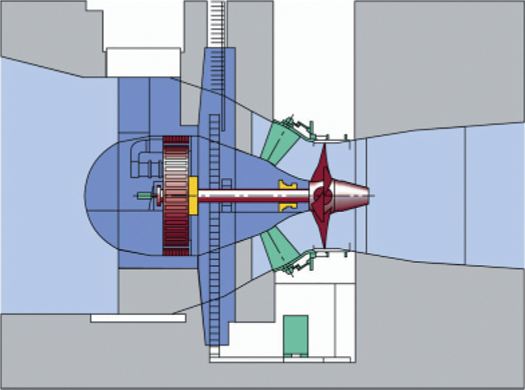
Figure 9.5 Bulb turbine with generator. Source: Voith Hydro.
For larger heads of up to 700 m the Francis turbine is used. It was developed in 1848 by James Bicheno Francis, who was born in England and emigrated to the United States when he turned 18. This turbine also uses the pressure difference of water and reaches efficiencies of over 90%. In principle, the Francis turbine can also be used as a pump and is therefore suitable as a pump turbine for pumped-storage plants (see Figure 9.6).
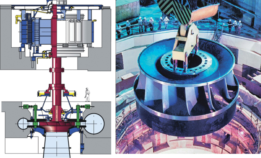
Figure 9.6 Francis pump turbine at Goldisthal pumped-storage plant (left) and a Francis turbine at the Itaipu plant (right). Source: Voith Hydro.
In 1880 the American Lester Allen Pelton developed the Pelton turbine. It is mainly designed for large heads and, consequently, for use in high mountains. This turbine can reach very high efficiencies of 90–95%. The water is supplied to the turbine over a penstock. It then flows through a nozzle at very high velocity to spoon-shaped buckets.
Small plants use the Ossberger turbine, which is also called a cross-flow turbine. These turbines reach somewhat lower efficiencies of around 80%. The turbine is divided into three parts that can be powered separately by water. This helps the system cope with fluctuations in the water runoff of small rivers (see Figure 9.7).
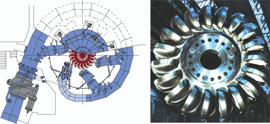
Figure 9.7 Drawing of a six-nozzle Pelton turbine (left) and photo of a Pelton turbine (right). Source: Voith Hydro.
9.3 Hydropower Plants
The energy that can be exploited from water essentially depends on two parameters: runoff volume and the head of the water. Almost all hydropower plants utilize natural elevation differences using technical equipment.
9.3.1 Run-of-River Hydropower Plants
The natural course of a river itself concentrates large quantities of water. A run-of-river hydropower plant can be built anywhere on a river where a sufficient difference in elevation exists (Figure 9.8). A weir then backs up the water. This creates a difference in elevation in the water's surface above and below the plant. At the top the water flows through a turbine that powers an electric generator. Grating at the turbine intake prevents rubbish and flotsam washed along by the river from blocking up the turbine. A transformer then converts the voltage of the generator into the desired mains voltage.
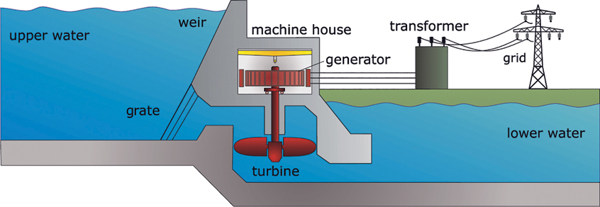
Figure 9.8 Principle of a run-of-river hydropower plant.
Large hydropower plants are usually constructed so that multiple turbines can run in parallel. If the water flow drops during dry periods of the year, some of the turbines can be shut down. The remaining turbines then still receive almost the full amount of water they need. This prevents the turbines from working in partial-load mode with poor efficiency. If, on the other hand, there is flooding, and a river carries more water with it than the turbines can process, the surplus water must be let out, unused, over a weir.
Barrages can present an obstacle for shipping and animals that live in rivers. Locks installed parallel to a barrage enable ships or boats to overcome the difference in water height. A certain amount of residual water flows through a fish bypass system next to the weir. This enables fish and other aquatic creatures to move freely across the weir system.
Germany's largest run-of-river power plants are located on the Rhine. Many plants, such as the run-of-river plant at Laufenberg on the Rhine (Figure 9.9), were built in the first half of the twentieth century. Existing plants that have been modernized have been able to improve performance. The best example in Germany is the Rheinfelden power plant, which was built in 1898 and is currently being modernized. The new facility, due for completion in 2011, will increase power from 25.7 to 100 MW and more than triple electricity production. At the same time modern fish bypasses are improving the ecological situation.
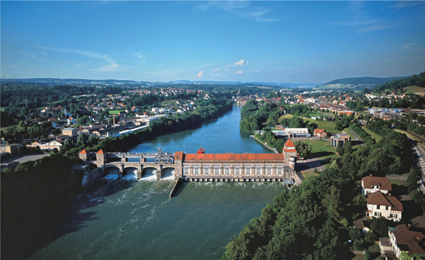
Figure 9.9 Run-of-river hydropower plant at Laufenburg. Source: Energiedienst AG.
Europe has very strict environmental conditions for new energy plants and for those being modernized. Consequently, it is not anticipated that electricity generation from run-of-river power plants will increase substantially.
As the height difference in water levels with run-of-river plants is usually only a few metres, very few plants have an output of more than 100 MW of electric power. Furthermore, run-of-river plants tend to be difficult to regulate. They supply electricity around the clock, but because the currents of a river cannot be controlled, surplus water remains unused if the power is not needed.
9.3.2 Storage Power Plants
Storage or impoundment hydropower plants produce high levels of power output. Dams store huge masses of water at geographically optimal locations. This type of dam makes it possible for storage power plants to be built in the mountains (Figure 9.10). A high-pressure pipeline pumps the water into a machine house, where enormous water pressure of up to 200 bars is created. In the machine house, water powers the turbines that produce energy via an electric generator.

Figure 9.10 Examples of storage power plants in Austria: Malta (left), Kaprun (right). Source: Verbund, www.verbund.at.
It is not unusual to find dams over 100 m high. The tallest dams on Earth are over 300 m high. Reservoirs are often also used to store drinking water and to control flooding. The Rappbode Dam in the Harz Mountains is the tallest dam in Germany at 106 m. It is mainly used for storing drinking water. The power plant output is comparatively low at 5.5 MW.
If storage hydropower plants are designed mainly for power generation, they achieve significantly higher outputs. Power plants with several hundred or even thousand megawatts are not uncommon (Table 9.1).
Table 9.1 The largest hydroelectric power plants in the world
| Power plant | Country | River | Completed | Capacity in MW | Dam length in m | Dam height in m |
| Three Gorges | China | Yangtse | 2008 | 22 400 | 2335 | 181 |
| Itaipú | Brazil/ Paraguay | Paraná | 1983 | 14 000 | 7760 | 196 |
| Xiluodu | China | Jinsha Jiang | 2014 | 13 860 | 698 | 286 |
| Guri | Venezuela | Rio Caroni | 1986 | 8 850 | 7500 | 162 |
| Tucuruí | Brazil | Rio Tocantins | 1984 | 8 370 | 6900 | 106 |
| Grand Coulee | USA | Columbia River | 1942 | 6 809 | 1592 | 168 |
Storage power plants can be constructed with a second basin located at a lower elevation by the machine house. Special pump turbines can then pump the water from the lower basin back up to the higher basin. This is called a pumped-storage hydropower plant.
9.3.3 Pumped-storage Hydropower Plants
Pumped-storage power plants need very specific geographical conditions. To be viable, they need two basins with a significant difference in altitude between them. Some pumped-storage plants have a natural inflow where a river flows into the higher basin. Pumped-storage plants without a natural inflow are purely storage plants.
When electric power is needed, the water of the higher basin is pumped over an intake mechanism through a pressure pipe to the turbine, which drives an electric machine as the generator. Once the turbine has extracted the energy from the water, the water flows into the lower basin. There, a transformer converts the voltage of the generator to mains voltage (Figure 9.11).
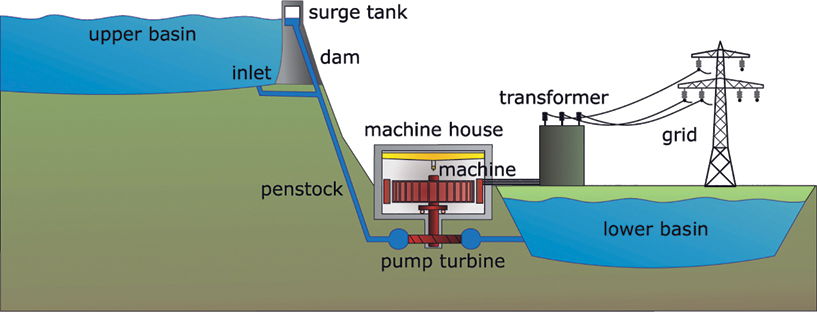
Figure 9.11 Principle of a pumped-storage power plant.
When electricity surpluses occur in the grid, the pumped-storage plant switches over to pumping operation. The electric machine then functions as a motor that drives the pump turbine. The pump turbine pumps the water from the lower to the higher basin once again. Major fluctuations in pressure can occur when the generator is switched to pumping operation, and, in extreme cases, these fluctuations can cause damage to the pressure pipe or other system parts. A surge tank regulates this change in pressure.
Pumped-storage power plants reach efficiencies of 70–90%. A good 70% of the electric energy that is necessary for pumping the water to the higher level can be replaced during the operation of the generator. Despite the losses, pumped-storage plants are very attractive economically. When a surplus of supply exists, electricity can usually be obtained very inexpensively. On the other hand, if electricity is in low supply, a plant can feed the energy back into the grid at a higher price.
Pumped-storage power plants have grown in importance in recent years. They can help to compensate for fluctuations from renewable power plants such as photovoltaic or wind power plants. For a fully renewable electricity supply, however, a considerably larger storage capacity is required than pumped-storage power plants in Germany could supply.
Germany's largest pumped storage power plant is located in Thuringia. The Goldisthal power plant (Figure 9.12), commissioned in 2003, has four generators which together have an output of 1060 MW. The accumulated dam volume of the upper basin is 12 million cubic metres. Based on this volume and with an average head of 302 m, the power plant can work at full capacity for eight hours. This is sufficient to cover the electricity demand of over 2.7 million average households.
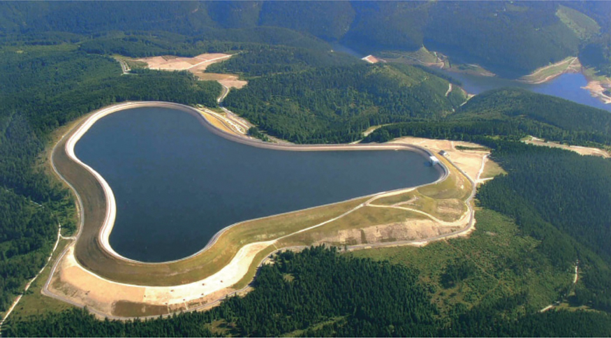
Figure 9.12 The Goldisthal pumped-storage power plant in Germany. Source: Vattenfall Europe.
9.3.4 Tidal Power Plants
Tidal waves are attributed to the interaction of the forces of attraction between the moon, the sun and Earth. As a result of the rotation of the Earth, the forces of attraction are continuously changing their direction. The water masses of the oceans follow the attraction. As a result, a tidal wave with a height difference of more than 1 m can form on the open sea. Tidal waves caused by the moon occur approximately every 12 hours at some point on Earth. In extreme cases, they can reach more than 10 m in height. Tidal power plants could use these changes in water level to generate energy.
In regions with a high tidal hub, a reservoir can be built so that water flows into it at high tide. The incoming water flows into the reservoir through a turbine in the dam wall, and at low tide it flows back again. The turbine and the connected generator convert the energy of the water into electric energy. The energy output is not continuous, so output drops to zero when the tide goes out.
Tides were used by tidal mills even during the Middle Ages. Worldwide there are only very few modern tidal power plants in operation today. The best-known one is the Rance power plant in France, which is situated on the estuary of the river of the same name and came into operation in 1967. It has a power output of 240 MW. The dam wall that seals off the 22 km2 basin is 750 m long. The environmental impacts of the separation of the estuary from the ocean are considerable. Corrosion by salty sea water is also causing some problems.
Tidal power plants are comparatively expensive to operate, so it is not likely that many new plants will be built. Due to the relatively minor differences between ebb and flow, most countries do not have suitable locations for these plants.
9.3.5 Wave Power Plants
For decades, high hopes have been pinned on the development of wave power plants. A study of the potential of wave energy indicates that large amounts of energy could be generated. However, only coastal regions with low water depths are appropriate for the use of wave energy. Due to the comparatively small usable sea areas available in many countries, this technology has relatively low potential.
Basically, a distinction is made between the following functions:
- Float systems
- Chamber systems
- TapChan systems
Float systems use the energy potential of waves. A floating body follows the movement of waves. Part of the installation is anchored to the ground. The movement of the floating body can be used by a piston or a turbine.
With chamber systems, a chamber locks in air. The waves cause the water level to fluctuate in the chamber. The oscillating water level compresses the air. The displaced air escapes through an opening and powers a turbine and a generator. When the water column falls, the air flows back through the turbine into the chamber (Figure 9.13).
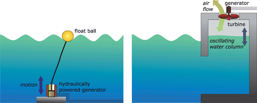
Figure 9.13 Principle of wave power plants. Left: Float system. Right: Chamber system.
TapChan is an abbreviation for ‘tapered channel’. In these systems, waves in coastal areas or on a floating object feed into a tapered and rising channel. An upper basin captures the waves. When the water flows back into the ocean, it powers a turbine.
Although numerous prototypes have been developed for wave power plants in recent decades, they have not yet caught on to any great extent. The main problem is the extreme fluctuation in conditions at sea. On the one hand, technical systems must be designed to save on materials and be cost-effective; on the other hand, storms with giant waves place extreme pressure on system survival. Many prototype installations have already fallen victim to storms. However, large companies have now become involved in the development of wave power plants, so it is likely that these problems will be solved in due course.
9.3.6 Ocean Current Power Plants
Ocean current power plants have a structure similar to wind power plants, except that the rotors rotate below the water surface. A built-in hub mechanism raises the rotor to the water surface for maintenance. The first prototype was successfully installed in 2003 off the North Devon coast in England [Bar04] (see Figure 9.14).

Figure 9.14 Left: Prototype system in the Seaflow project off the west coast of England. Right: Maintenance ship in a planned ocean current power plant park. Photo: ISET.
Graphics: MCT.
In principle, the physical characteristics of wind power plants are similar to those of ocean current plants. The main difference is that, because water has a higher density than air, ocean current plants can achieve higher output yields than wind power plants even when the speed of currents is low.
Ocean current plants are limited to regions with relatively consistent high current speeds and moderate water depths of up to 25 m. These conditions mainly exist on headlands and bays, between islands and in straits. Although shipping lanes often restrict this kind of use, major potential exists. In Germany, for example, it would make sense to build a plant at the southern tip of Sylt. In the medium term, ocean current power plants could become another building block in the generation of a climate-compatible electricity supply, as technological advances and the benefits of mass production are rapidly leading to cost reductions.
9.4 Planning and Design
All types of hydropower plants require different and sometimes complex planning and design. It is only possible here to outline some of the basic planning aspects. The first requirement for a run-of-river power plant is the collection of information about the stretch of water where the plant is to be built. The most important parameter is the runoff of the river's water over the course of a year – that is, the volume of water that flows through the river. Each river has its own typical annual flow characteristic that is influenced mainly by rain and melting snow. For further design purposes, the river runoff volumes are categorized to obtain an annual continuous curve. This indicates the number of days per year when a river achieves or exceeds a certain runoff volume (Figure 9.15).
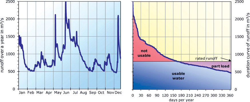
Figure 9.15 Annual flow characteristics and annual continuous curve for the Rhine runoff near Rheinfelden.
A rated runoff for a river is established, which represents the water volume at which a power plant produces its full output. If the runoff volume exceeds the rated runoff, the surplus water must be diverted unused over a weir. To maximize electricity generation, turbines with a high rated runoff should be selected. However, if the runoff volume of the river drops below the rated runoff, there will not be enough water to enable the power plant to provide its full output. The turbines will then either work at poor efficiency in partial load mode or individual turbines will be switched off and remain unused. A low rated runoff should be selected to ensure that optimal use is being made of the turbines. In practice, the rated runoff is determined based on a compromise between the maximum amount of power to be generated and optimal use of the turbine.
 Power Output of a Run-of-River Power Plant
If the water runoff quantity Q and the head H of the water at a power plant are known, then the electric power output of a hydropower plant can be calculated relatively easily, based on the efficiency η of the plant, the density of the water ρW (ρW ≈ 1000 kg m−3) and the gravitational acceleration g (g = 9.81 m s−2):
With an extension runoff quantity of 1355 m3 s−1, a head of 10.1 m and efficiency of 79% = 0.79, the output for full load at the Laufenburg hydropower plant on the Rhine can be calculated as
At 5940 full-load hours per year, the power plant generates 106 MW × 5940 h = 630 000 MWh = 630 million kWh. This is sufficient to cover the average electricity consumption of 180 000 households in Germany.
To build a hydroelectric power plant, statutory approval is required. Approval is usually granted for 30 years, but it may be given for a longer period. The procedure for obtaining approval can take 3–10 years. For large-scale power plants, the approval also includes a test for environmental compatibility. The EU water rights guidelines stipulate that all water bodies in Europe must be kept in a ‘good state’. Although the water may be used, its ecological functioning must remain intact. In this context the current state of the water body concerned is also crucial. Therefore, it is much easier to gain approval to modernize a power plant on a stretch of water that has already been greatly altered than to build a new plant. For this reason, the chances of obtaining approval to build new large-scale hydropower plants are not very favourable.
9.5 Economics
Hydroelectric power plants are considered the most cost-effective option for supplying renewable electricity today. This applies mainly to older systems where the construction costs have largely already been written off. The relatively high construction costs and long amortization periods for new sites substantially increase the cost of generating electricity.
For small plants, fewer than five megawatts, the investment in modernization amounts to between €2500 and €5000 kW−1; for the reactivation of a plant or a new plant it is between €5000 and €13 000 kW−1. The costs for larger plants are somewhat lower but depend greatly on local conditions. In addition to the investment and operating costs, large-scale hydropower plants may also have to pay a fee for water use.
With existing medium-sized plants in the power range between 10 and 100 MW, the cost of generating electricity is less than 2 cents per kilowatt hour. For new plants this cost can increase up to 4–10 cents per kilowatt hour [Fic03]. The costs for small plants can even be higher.
In Germany, payments for electricity from new hydropower plants are regulated by the Renewable Energy Sources Act (EEG). Accordingly, the revenue for electricity from hydropower plants with a capacity of less than 500 kW amounts to 12.4 cents per kilowatt hour; plants between 500 kW and 2 MW receive 8.17 cents per kilowatt hour for 20 years. Lower rates are envisaged for larger capacities, so that from 50 MW this is only 3.47 cents per kilowatt hour. From 2018, an annual reduction of 1.5% is also envisaged.
9.6 Ecology
Hydropower plants are among the most controversial of all the renewable power plants. Conventional run-of-river, storage, and tidal power plants, in particular, have a huge impact on the natural environment.
Due to the barrage system, bodies of stationary water form in places where water flowing over pebbles and boulders previously provided a suitable habitat for many different kinds of fish. As a result of the changes to habitat, numerous fish and plants are becoming extinct. Another danger for fish is the hydroelectric turbines themselves. Although grating prevents large fish from entering the processing area of a plant, the metal bars of the grating let small creatures slip through and become injured or killed by the turbines. The barrier systems are often an insurmountable obstacle for migratory fish. Fish ladders that run alongside the barriers help enormously in improving the freedom of movement for fish (Figure 9.16). Nevertheless, barrier systems are still an obstacle for some species.
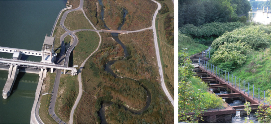
Figure 9.16 Left: Stream in the area of the Donaukraftwerk Freudenau power plant in Austria. Right: Fish ladder at the Weser power plant in Bremen. Source: Verbund, www.verbund.at. Source: Weserkraftwerk Bremen GmbH.
Large reservoirs flood wide areas of land and destroy people's homes as well as natural habitat. Sinking biomass decomposes in water and releases large quantities of climate-damaging methane. This problem can be reduced considerably if reservoir basins are carefully cleared before they are flooded.
Breaches in walls are another danger with large dams. Normally, dams are constructed so that they are largely earthquake-proof. But even the best construction is powerless against targeted terrorist attacks. Huge devastation will occur if the large volumes of stored water pour into a valley all at once.
The newly built Three Gorges dam in China is often cited as a negative example of the type of environmental damage hydropower plants can cause. Twenty cities and more than ten thousand villages, which together housed more than one million people, were sacrificed for the building of this plant. It is still unclear what the ecological impact has been on the flooded area. It is expected that the many environmental sins of the past will come back to haunt those who live in the area, for example by contaminating the groundwater. The fear is that the 600 km-long reservoir is turning into a cesspit of sewage and industrial waste.
On the other hand, the Three Gorges dam is designed to produce 84 billion kilowatt hours of electricity per year. This equates to more than one-eighth of total German demand. If modern coal-fired plants were used to generate the same amount of electricity, they would be emitting more than 70 million tons of carbon dioxide into the atmosphere each year. This corresponds to the total carbon dioxide emissions of Austria.
In this sense it is important to weigh the benefits and disadvantages of all hydropower plants. It is possible to build ecologically viable plants. The main thing is that ecological aspects are included in the equation along with protecting the environment and providing reasonably priced energy.
9.7 Hydropower Markets
About 16% of the electricity generated worldwide comes from hydropower plants. In 2004 Canada was still the leader in this field (Figure 9.17), but in the meantime it has been overtaken by China (Figure 9.17). The hydroelectric share of the power generated varies substantially from country to country. Whereas 100% of Norway's electricity comes from hydropower plants, this share is around 60% in Brazil, Canada, and Austria. The hydroelectric share for China and the USA is only 19% and 6%, respectively. At 3%, Germany's share is relatively insignificant. In Europe, Norway and Iceland have the highest percentage of hydroelectric energy, followed by the Alpine countries and Sweden.
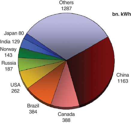
Figure 9.17 Electricity generation from hydropower plants in different countries. 2016. Source: Data: [BP17].
Large-scale plants, in particular, make a major contribution to the generation of electricity from hydropower. The Itaipu facility in Brazil, with the highest capacity in the world (Figure 9.18), generates more electricity than all hydropower plants in Germany and Austria combined.
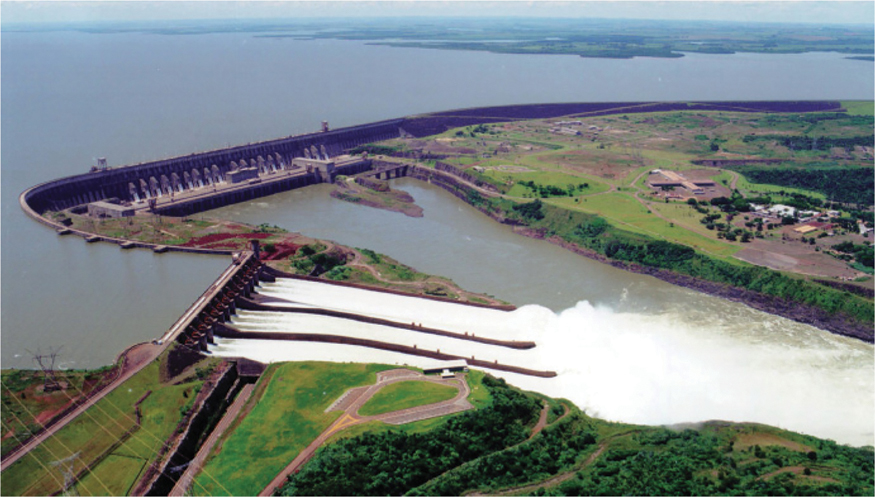
Figure 9.18 Aerial view of the Itaipu power plant. Photo: Itaipu Binacional, www.itaipu.gov.br.
In Germany, hydropower is mainly used in the southern federal states, where the rivers have a significantly greater gradient than in the north. In the flat north there are only a few small installations.
9.8 Outlook and Development Potential
Hydropower is the most developed method for power generation based on renewables. In the industrialized nations most of the potential has already been exploited. The potential for new large-scale plants now mainly exists in developing and emerging nations. In many industrialized countries there is also great potential for modernizing or upgrading barrages and dams. Classic run-of-river and storage hydropower plants could at best double the output of electricity generated worldwide. However, in the long term their share of energy production worldwide will decrease, because the demand for electricity will continue to rise.
Certain types of hydropower plants, such as wave and ocean current plants, which are not yet in use, show some promising potential for the future. However, substantial cost reductions are still needed before these types of power plants can have any major impact on the market.
The biggest advantage of hydroelectric energy is its relatively consistent output of power, compared to solar energy and wind power. This aspect makes it easier to plan a mix of different renewable energies. With the increase in renewable energy's contribution to electricity generation, storage, and pumped-storage power plants are also becoming important options due to their ability to offer consistency in electricity supply.