
Chapter 9
Sliding-Mode Synchronization Control for Fractional-Order Chaotic Systems with Disturbance
9.1 Problem Statement
On the basis of the Caputo definition of the fractional derivative (2.17), the FOCS will be introduced. Considering the following FOCS as the drive system:
where the fractional order satisfies ![]() ,
, ![]() denotes a constant matrix,
denotes a constant matrix, ![]() is a state vector, and
is a state vector, and ![]() is the nonlinear function vector.
is the nonlinear function vector.
The response system is defined as
where ![]() is the state vector,
is the state vector, ![]() is the nonlinear function vector,
is the nonlinear function vector, ![]() is the unknown bounded disturbance, and
is the unknown bounded disturbance, and ![]() is the control input.
is the control input.
This chapter aims to develop a FODO-based adaptive sliding-mode synchronization control scheme, in which synchronization is realized between two identical fractional-order chaotic systems in the presence of unknown external disturbances. On the basis of the designed sliding-mode controller, the response system can well synchronize the drive system under the proper condition. To obtain the main results, the following assumption is introduced.
9.2 Design of Fractional-Order Disturbance Observer
In this section, a FODO will be designed to approximate the external disturbance in the response system (9.2). Without loss of generality, according to the response system (9.2), we have
where ![]() is the
is the ![]() th element of
th element of ![]() ,
, ![]() is the
is the ![]() th element of
th element of ![]() ,
, ![]() is the
is the ![]() th element of
th element of ![]() ,
, ![]() is the
is the ![]() th element of
th element of ![]() ,
, ![]() is the
is the ![]() th element of
th element of ![]() , and
, and ![]() .
.
Since ![]() in Equation (9.2) is unknown,
in Equation (9.2) is unknown, ![]() cannot be applied to develop the synchronization control scheme for the drive system (9.1) and the response system (9.2). To overcome this problem, a fractional-order nonlinear disturbance observer is designed to estimate the disturbance
cannot be applied to develop the synchronization control scheme for the drive system (9.1) and the response system (9.2). To overcome this problem, a fractional-order nonlinear disturbance observer is designed to estimate the disturbance ![]() .
.
To design the FODO, an auxiliary variable is introduced based on the design technique of the integer-order disturbance observer as follows [105]:
where ![]() is a constant to be determined.
is a constant to be determined.
Considering Equations (9.3) and (9.4), the Caputo fractional derivative of ![]() can be written as
can be written as

To obtain the disturbance estimate, the estimate of the intermediate variable ![]() is described as
is described as
where ![]() is the estimate of
is the estimate of ![]() .
.
According to Equation (9.4), the disturbance ![]() can be estimated as
can be estimated as
Define ![]() . Considering Equations (9.4) and (9.7), we have
. Considering Equations (9.4) and (9.7), we have
Consider Equations (9.5) and (9.6); the Caputo fractional derivative of ![]() can be written as
can be written as
On the basis of these discussions, to analyze the convergence of disturbance estimation error ![]() , a Lyapunov function candidate can be chosen as
, a Lyapunov function candidate can be chosen as
Invoking Equation (9.10) and Lemma 2.1, the Caputo fractional derivative of ![]() is described as
is described as
Substituting Equation (9.9) into Equation (9.11), we obtain
According to Equation (9.12) and Assumption 9.1, we have

where ![]() and
and ![]() . To ensure that the estimation error is bounded, the design parameter
. To ensure that the estimation error is bounded, the design parameter ![]() of the FODO should be chosen to make
of the FODO should be chosen to make ![]() . The conclusion that the signals
. The conclusion that the signals ![]() and
and ![]() are bounded can be drawn from Equation (9.13) and Lemma 2.3.
are bounded can be drawn from Equation (9.13) and Lemma 2.3.
On the basis of Lemma 2.3 and Equation (9.13), we obtain

which means that

which demonstrates that the disturbance estimation error ![]() is upper bounded. For the external disturbance
is upper bounded. For the external disturbance ![]() ,
, ![]() , the disturbance approximation error
, the disturbance approximation error ![]() satisfies
satisfies ![]() , where
, where ![]() is an unknown positive constant. In actual applications, the upper bound of
is an unknown positive constant. In actual applications, the upper bound of ![]() is difficult to determine. Thus, the estimated value
is difficult to determine. Thus, the estimated value ![]() of
of ![]() is introduced, where
is introduced, where ![]() .
.
This design procedure of FODO can be summarized in the following theorem.
On the basis of these analyses, Theorem 9.1 can be easily proven.
9.3 Disturbance-Observer-Based Synchronization Control of Fractional-Order Chaotic Systems
In this section, a FODO-based adaptive sliding-mode control scheme will be proposed to guarantee that the trajectories of drive system (9.1) and response system (9.2) are ultimately bounded synchronized. To design the synchronization control scheme, we first define the error variable ![]() . From Equations (9.1) and (9.2), the corresponding synchronization error system is given as
. From Equations (9.1) and (9.2), the corresponding synchronization error system is given as
To investigate the stabilization of fractional-order synchronization error system (9.16), a simple sliding-mode surface is defined as
where ![]() .
.
From Equation (9.17), we have

where ![]() denotes the
denotes the ![]() th row of
th row of ![]() ,
, ![]() denotes the
denotes the ![]() th element of
th element of ![]() .
.
Using the adaptive sliding control approach, the desired synchronization control input is designed as
where ![]() is the sign function and
is the sign function and ![]() is a design constant. Meanwhile, the estimated value
is a design constant. Meanwhile, the estimated value ![]() is updated by
is updated by
where ![]() is a design constant.
is a design constant.
If the synchronization control scheme is designed as Equation (9.19) for the fractional-order synchronization error system (9.16), the sliding-mode surface ![]() satisfies
satisfies
where ![]() is an unknown constant.
is an unknown constant.
From Equations (9.17) and (9.21), one obtains
According to this discussion, if the sliding surface ![]() is bounded, then the synchronization error
is bounded, then the synchronization error ![]() is also bounded. Therefore, the FODO-based adaptive sliding-mode synchronization control scheme for fractional-order chaotic systems with unknown disturbances can be summarized in the following theorem, which will be proved using the fractional-order Lyapunov method.
is also bounded. Therefore, the FODO-based adaptive sliding-mode synchronization control scheme for fractional-order chaotic systems with unknown disturbances can be summarized in the following theorem, which will be proved using the fractional-order Lyapunov method.
9.4 Simulation Examples
9.4.1 Synchronization Control of Modified Fractional-Order Jerk System
Yu [232] investigated a new chaotic generator by constructing a three-segment piecewise-linear odd function with variable breakpoint. From the differential equation of chaotic generator [232], the modified fractional-order jerk system is given as follows:

where ![]() ,
, ![]() , and
, and ![]() are system state variables, the parameters
are system state variables, the parameters ![]() and
and ![]() , and
, and ![]() is a piecewise linear function defined by
is a piecewise linear function defined by
where ![]() and
and ![]() ,
, ![]() .
.
According to the system (9.38) and the piecewise linear function (9.39), the three equilibrium points of the modified fractional-order jerk system are given in Table 9.1. The Jacobian matrix for the system (9.38) can be written as

On the basis of Table 9.1, the corresponding eigenvalues for equilibrium point ![]() are
are ![]() and
and ![]() . For equilibrium points
. For equilibrium points ![]() and
and ![]() , the eigenvalues are
, the eigenvalues are ![]() and
and ![]() . When the fractional order
. When the fractional order ![]() is chosen, we obtain the following characteristic equation of the equilibrium points
is chosen, we obtain the following characteristic equation of the equilibrium points ![]() and
and ![]() :
:
with unstable ![]() and
and ![]() , in which
, in which ![]() (
(![]() is the lowest common multiple of the fractional-order denominator). Thus, the modified fractional-order jerk system (9.38) has chaotic dynamic behaviors based on the literature [164]. When the initial values are chosen as
is the lowest common multiple of the fractional-order denominator). Thus, the modified fractional-order jerk system (9.38) has chaotic dynamic behaviors based on the literature [164]. When the initial values are chosen as ![]() and the fractional order
and the fractional order ![]() , the fractional-order modified jerk system exhibits chaotic behaviors, as shown in Figure 9.1.
, the fractional-order modified jerk system exhibits chaotic behaviors, as shown in Figure 9.1.
Table 9.1 Equilibrium points of the modified fractional-order jerk system
| Linear region | Equilibrium points | |

Figure 9.1 Chaotic behaviors of modified fractional-order jerk system: (a)  –
– plane; (b)
  –
– plane; (c)
  –
– plane; (d)
  –
– –
– space.
In this section, to illustrate the effectiveness of the proposed synchronization controller, the synchronization of the modified fractional-order jerk system (9.38) is investigated. Consider the FOCS (9.38) as a drive system. From Equation (9.2), the response system is defined as follows:

where ![]() ,
, ![]() , and
, and ![]() are system state variables,
are system state variables, ![]() ,
, ![]() , and
, and ![]() are unknown bounded disturbances,
are unknown bounded disturbances, ![]() ,
, ![]() , and
, and ![]() are designed synchronization control inputs, and
are designed synchronization control inputs, and ![]() is defined as
is defined as
According to Equations (9.38) and (9.42), the synchronization error system can be written as follows:

where ![]() ,
, ![]() , and
, and ![]() are synchronization error variables.
are synchronization error variables.
Referring to the designed controller (9.19), the synchronization controller can be written as follows:

Substituting Equation (9.45) into Equation (9.44), we have the following:

where ![]() , with
, with ![]() and
and ![]() .
.
To demonstrate the effectiveness of the proposed FODO-based adaptive sliding-mode synchronization control scheme, numerical simulation results are presented for the modified fractional-order jerk system under the following conditions: initial conditions are chosen as ![]() ,
, ![]() ,
, ![]() , and
, and ![]() , design parameters are chosen as
, design parameters are chosen as ![]() ,
, ![]() ,
, ![]() , and
, and ![]() . Disturbances are assumed as
. Disturbances are assumed as ![]() ,
, ![]() , and
, and ![]() . On the basis of the result of Ishteva [225], we have
. On the basis of the result of Ishteva [225], we have ![]() , where
, where ![]() denotes the square root of minus one, and
denotes the square root of minus one, and ![]() and
and ![]() are arbitrary numbers. In this simulation, the parameter
are arbitrary numbers. In this simulation, the parameter ![]() and the fractional order
and the fractional order ![]() . Thus,
. Thus, ![]() can be used to approximate
can be used to approximate ![]() . The comparison result is shown in Figure 9.2 for
. The comparison result is shown in Figure 9.2 for ![]() and
and ![]() . According to Figure 9.2, Assumption 9.1 is satisfied.
. According to Figure 9.2, Assumption 9.1 is satisfied.

Figure 9.2 Comparison result of  and
and  .
.
Numerical results are shown in Figure 9.3 and Figure 9.4 under the proposed FODO-based adaptive sliding-mode control scheme. State synchronization results of the drive system (9.38) and the response system (9.42) are given in Figure 9.3a–c. It is shown that good synchronization performance is achieved. Figure 9.3d shows that the synchronization errors ![]() ,
, ![]() , and
, and ![]() are convergent. Furthermore, the disturbance observation performance of the proposed FODO (9.6) and (9.7) is presented in Figure 9.4. It is evident from Figure 9.4 that the disturbance observer is effective and feasible. According to the simulation results, the drive system (9.38) and the response system (9.42) are bounded synchronized under the designed sliding-mode controller (9.19) and the adaptive update law (9.20). Therefore, the proposed FODO-based adaptive sliding-mode synchronization control scheme is valid for fractional-order chaotic systems with external disturbance.
are convergent. Furthermore, the disturbance observation performance of the proposed FODO (9.6) and (9.7) is presented in Figure 9.4. It is evident from Figure 9.4 that the disturbance observer is effective and feasible. According to the simulation results, the drive system (9.38) and the response system (9.42) are bounded synchronized under the designed sliding-mode controller (9.19) and the adaptive update law (9.20). Therefore, the proposed FODO-based adaptive sliding-mode synchronization control scheme is valid for fractional-order chaotic systems with external disturbance.
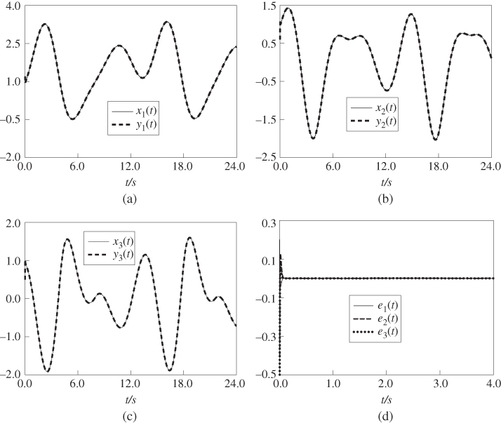
Figure 9.3 Synchronization control results of modified fractional-order jerk system: (a)  and
and  ; (b)
; (b)  and
and  ; (c)
; (c)  and
and  ; (d) synchronization errors
  ,
,  , and
, and  .
.

Figure 9.4 Disturbance observer results of the modified fractional-order jerk system: (a)  and
and  ; (b)
; (b)  and
and  ; (c)
; (c)  and
and  ; (d) observation errors
  ,
,  , and
, and  .
.
9.4.2 Synchronization Control of Fractional-Order Liu System
To further illustrate the effectiveness of the proposed synchronization controller, synchronization of the fractional-order Liu system [233] is studied in this section. The fractional-order Liu system is given as follows:

where ![]() is the fractional order,
is the fractional order, ![]() ,
, ![]() , and
, and ![]() are system state variables, and
are system state variables, and ![]() ,
, ![]() , and
, and ![]() are system parameters. The fractional order is chosen as
are system parameters. The fractional order is chosen as ![]() , the system parameters are set as
, the system parameters are set as ![]() ,
, ![]() , and
, and ![]() and the initial conditions are chosen as
and the initial conditions are chosen as ![]() . The simulation results of the fractional-order Liu system are shown in Figure 9.5.
. The simulation results of the fractional-order Liu system are shown in Figure 9.5.
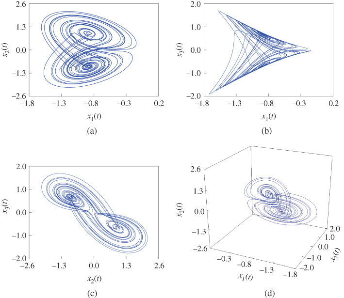
Figure 9.5 Dynamic behaviors of fractional-order Liu system: (a)  –
– plane; (b)
  –
– plane; (c)
  –
– plane; (d)
  –
– –
– space.
To develop the synchronization control scheme, the fractional-order Liu system (9.47) is taken as the drive system, and the response system is constructed as follows:

where ![]() ,
, ![]() , and
, and ![]() are system state variables,
are system state variables, ![]() ,
, ![]() , and
, and ![]() are unknown bounded disturbances, and
are unknown bounded disturbances, and ![]() ,
, ![]() , and
, and ![]() are designed synchronization control inputs.
are designed synchronization control inputs.
According to Equations (9.47) and (9.48), the synchronization error system can be written as follows:

where ![]() ,
, ![]() , and
, and ![]() are synchronization error variables.
are synchronization error variables.
Invoking the designed controller (9.19), the synchronization controller is given by the following:

Substituting Equation (9.50) into Equation (9.49), we have the following:

where ![]() , with
, with ![]() and
and ![]() .
.
For the numerical simulation, we choose the fractional order as ![]() ; the disturbances are assumed as
; the disturbances are assumed as ![]() . The initial conditions are chosen as
. The initial conditions are chosen as ![]() ,
, ![]() ,
, ![]() , and
, and ![]() . The control parameters are designed as
. The control parameters are designed as ![]() ,
, ![]() , and
, and ![]() .
.
According to these conditions and the proposed synchronization control scheme, numerical results are presented in Figure 9.6 and Figure 9.7. Good synchronization performance is shown in Figure 9.6a–c. Numerical results of the synchronization errors ![]() ,
, ![]() , and
, and ![]() are given in Figure 9.6d. Furthermore, the observation performance of the proposed FODO (9.6) and (9.7) is presented in Figure 9.7. It shows that the disturbance observer is effective based on the estimation performance of the designed FODO. On the basis of the simulation results, the drive system (9.47) can synchronize the response system (9.48) well based on the designed sliding-mode controller (9.19) and the adaptive update law (9.20). Thus the proposed adaptive sliding-mode synchronization control method is effective for fractional-order chaotic systems with external disturbance.
are given in Figure 9.6d. Furthermore, the observation performance of the proposed FODO (9.6) and (9.7) is presented in Figure 9.7. It shows that the disturbance observer is effective based on the estimation performance of the designed FODO. On the basis of the simulation results, the drive system (9.47) can synchronize the response system (9.48) well based on the designed sliding-mode controller (9.19) and the adaptive update law (9.20). Thus the proposed adaptive sliding-mode synchronization control method is effective for fractional-order chaotic systems with external disturbance.

Figure 9.6 Synchronization control results of fractional-order Liu system: (a)  and
and  ; (b)
; (b)  and
and  ; (c)
; (c)  and
and  ; (d) synchronization errors
  ,
,  , and
, and  .
.

Figure 9.7 Disturbance observer results of the fractional-order Liu system: (a)  and
and  ; (b)
; (b)  and
and  ; (c)
; (c)  and
and  ; (d) observation errors
  ,
,  , and
, and  .
.
9.5 Conclusion
In this chapter, a FODO-based adaptive sliding-mode synchronization control scheme has been studied for fractional-order chaotic systems in the presence of external disturbance. A FODO has been developed to approximate the unknown disturbances. A sliding-mode synchronization controller has been designed based on the FODO for synchronization of fractional-order chaotic systems. Furthermore, two examples are given, i.e., synchronization between two modified fractional-order jerk systems and synchronization between two fractional-order Liu systems. Numerical simulations show the effectiveness of the proposed FODO-based adaptive sliding-mode synchronization control scheme.