What You'll Learn in This Hour:
How to model classes that consist of other classes
How to model interfaces and their connections with classes
The concept of visibility
You've learned about associations, multiplicities, and inheritance. You're almost ready to create meaningful class diagrams. In this hour, you'll learn the final pieces of the puzzle, as you delve into additional types of relationships and other issues connected with classes. The ultimate goal is to be able to create a static view of a system, complete with all the interconnections among the system's classes.
Sometimes a class consists of a number of component classes. This is a special type of relationship called an aggregation. The components and the class they constitute are in a part-whole association. In Hour 2, “Understanding Object-Orientation,” I mentioned that your home computer system is an aggregation that consists of a CPU box, a keyboard, a mouse, a monitor, a CD-ROM drive, one or more hard drives, a modem, a disk drive, a printer, and possibly some speakers. Along with the drives, the CPU box holds RAM, a graphics card, and a sound card (and probably some other items).
You represent an aggregation as a hierarchy with the “whole” class (for instance, the computer system) at the top and the components below. A line joins a whole to a component, with an open diamond on the line near the whole. Figure 5.1 shows the computer system as an aggregation.
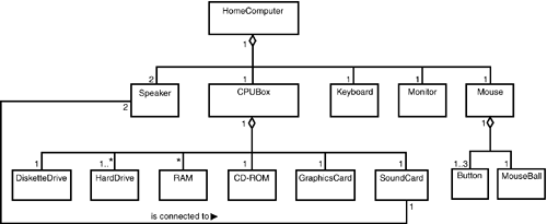
Figure 5.1. An aggregation (part-whole) association is represented by a line between the component and the whole with an open diamond adjoining the whole.
Although this example shows each component belonging to one whole, in an aggregation this isn't necessarily the case. For example, in a home entertainment system, a single remote control might be a component both of a television and of a VCR.
Sometimes the set of possible components in an aggregation falls into an Or relationship. In some restaurants, a meal consists of soup or salad, a main course, and a dessert. To model this, you would use a constraint—the word or within curly brackets on a dotted line that connects the two part-whole lines, as Figure 5.2 shows.
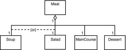
Figure 5.2. You can place a constraint on an aggregation to show that one component or another is part of the whole.
Consistency in Constraints
Note the consistency between the use of {or} in Figure 5.2 (which shows a constraint on an aggregation) and the previous use of {or} in Figure 4.6 (which shows a constraint in an association).
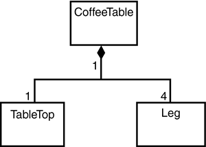
A composite is a strong type of aggregation. Each component in a composite can belong to just one whole. The components of a coffee table—the tabletop and the legs—make up a composite. The symbol for a composite is the same as the symbol for an aggregation except the diamond is filled, as shown in Figure 5.3.
The composite is one way to show the components of a class. If you want to give the sense of showing the class's internal structure, you can go a step further with the UML 2.0 composite structure diagram.
Here's an example. Suppose you're creating a model of a shirt. Figure 5.4 shows the shirt as a large class rectangle with its components nested inside. The nested diagram shows how the components of the shirt relate to one another.

Figure 5.4. A composite structure diagram shows the components of a class as a diagram nested inside a large class rectangle.
The composite structure diagram focuses attention on the shirt and its internal components.
This type of diagramming isn't totally new in UML 2.0. In version 1.x this was a technique called context diagramming.
In Hour 2, I mentioned encapsulation—the idea that an object hides its operations from other objects. When you lock your car, for example, the car doesn't show you how it performs the lockup operation. When you change channels on your TV, your TV doesn't let you see how it's done. If these operations are hidden, how do you get the car or the TV to perform them?
The car and the TV both receive a message (a request to perform an operation) through an interface. An interface is a set of operations that specifies some aspect of a class's behavior, and it's a set of operations a class presents to other classes.
An example will help clarify the interface concept. Every time you use a washing machine, you don't rip it apart to get to the underlying circuitry so that you can turn it on and set the time parameters. You don't get into the plumbing to start and stop the water flow. Instead, you get the washing machine to perform those operations by turning a control knob, shown in Figure 5.5. As a result of manipulating the knob, you can turn the machine on or off or set some parameter related to washing your clothes.
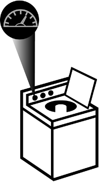
Figure 5.5. The control knob, an interface to a washing machine, allows you to get the washing machine to carry out some of the washing machine's operations.
The control knob is the washing machine's interface. What operations does the control knob have? They're pretty simple. The control knob can close a connection or break a connection, and it can turn clockwise or counterclockwise by some number of degrees.
The control knob's operations are, in a sense, abstract. Closing or breaking a connection, turning clockwise or counterclockwise—these don't accomplish anything of value unless the control knob is attached to something. In this case it's attached to a washing machine. It's almost as if the washing machine makes the control knob's operations “real” by translating them into washing-related operations—like turning the machine on or off, or setting a parameter (the duration of the wash cycle, for example).
In UMLspeak, we'd say that the washing machine guarantees that part of its behavior will “realize” the control knob's behavior. For this reason, the relationship between a class and its interface is called realization.
Why “part of its behavior”? Because it's not the case that all of the washing machine's operations have to do with control knobs. Some operations, like acceptClothes() and acceptDetergent(), are accessible via the washing machine's drum.
Throughout all this, you might have noticed numerous references to an interface's operations, but nothing about its attributes. That's because as far as we're concerned, it doesn't have any. Yes, a control knob has a radius and thickness, and perhaps attributes like make and model. The point is that we don't care about them. When it comes to interfaces, all we're concerned with are their operations.
You model an interface the same way you model a class, with a rectangle icon. The difference is that this icon has no attributes. You'll recall that you can elide the attributes out of the representation of a class. How then do you distinguish between an interface and a class that just doesn't show its attributes? One way is to add the keyword «interface» above the name of the interface in the rectangle. Another is to put the letter I at the beginning of the name of any interface.
The symbol for the realization relationship between a class and its interface looks like the symbol for inheritance, except the line to the open triangle is dashed instead of solid. Figure 5.6 shows the realization between WashingMachine and ControlKnob.
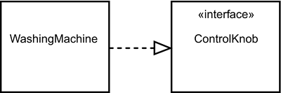
Figure 5.6. An interface is a collection of operations that a class carries out. A class is related to an interface via realization, indicated by a dashed line with an open triangle that points to the interface.
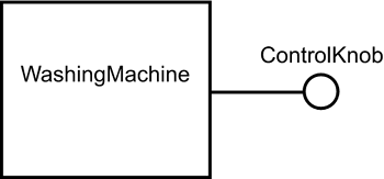
Another (elided) way to represent a class and an interface is with a small circle connected by a line to the class, as in Figure 5.7. (This is sometimes called a lollipop diagram.)
Inheritance Versus Realization
Because of the similarity in the notation for inheritance and the notation for realization, you might take a moment to consider these two. Think of inheritance as the relationship between a parent and a child: The parent passes on physical attributes (eye color, hair color, and so on) to the child, and the child also takes on behaviors from the parent. Think of realization as something like the relationship between a teacher and a student: The teacher doesn't pass on any physical attributes to the student, but the student learns behaviors and procedures from the teacher. The student might reuse those behaviors to accomplish his or her own goals.
A class can realize more than one interface, and an interface can be realized by more than one class.
Interfaces Everywhere
Interfaces are all around us. In fact, we're so accustomed to seeing them that we typically think of them as integral parts of whatever they happen to be attached to.
Control knobs, in particular, are part of all kinds of appliances. In addition to helping us manipulate washing machines, for example, they enable us to turn radios on and off and to adjust the volume and the reception. You can undoubtedly think of all kinds of other places where you see control knobs.
Leveraging our intuitive use of this little interface, one enterprising company markets a control knob as an input device for computers: Nashville, Tennessee-based Griffin Technology sells PowerMate, a USB-connected control knob you can program to perform just about any function you can do with a keyboard. Proud owners typically say, “It's incredibly useless—and I use it every day!”
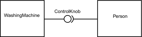
Because we depend on the interface to get us to the washing machine's operations, we model the interaction through the interface as a dependency. In Hour 4, “Working with Relationships,” you saw that the dependency symbol is a dashed line with an arrowhead. Figure 5.8 shows what I mean.

In UML 1.x, the dependency arrow worked with both the full and elided notations for the interface. UML 2.0 introduces the “ball-and-socket” symbol for the elided version (see Figure 5.9).
UML 2.0 takes the interface concept a step further by allowing you to model the connection between an interface and a class.
Think of your mouse as an interface to your computer. You can do a couple of things with it—point and click (and roll that little wheel in the middle, if you have that kind of mouse). By themselves these operations are worthless until your computer “realizes” them. That is, you can use these operations to locate the cursor and to select items.
How does the mouse connect to your computer? Follow the cable from the mouse to the back of your computer and you'll see a port—an access point that the mouse plugs into. Of course, your computer also has a serial port, a parallel port, and one or more USB ports. These ports are the points through which the computer interacts with its environment.
UML 2.0 provides a symbol that models these interaction points. As Figure 5.10 shows, the port symbol is a small square on the border of the class icon, and the square is connected to the interface.
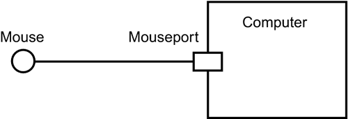
Figure 5.10. UML 2.0's symbol for the port shows the point through which a class interacts with its environment.
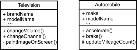
Closely related to interfaces and realizations is the concept of visibility. Visibility applies to attributes or operations and specifies the extent to which other classes can use a given class's attributes or operations (or an interface's operations). Three levels of visibility are possible. At the public level, usability extends to other classes. At the protected level, usability is open only to classes that inherit from the original class. At the private level, only the original class can use the attribute or operation. In a television set, changeVolume() and changeChannel() are public operations, paintImageOnScreen() is a private one. In an automobile, accelerate() and brake() are public operations, updateMileageCount() is protected.
Realization, as you might imagine, implies that the public level applies to every operation in an interface. Shielding the operations via either of the other levels would make no sense, as an interface is intended for realization by a multitude of classes.
To denote the public level, precede the attribute or operation with a “+”; to denote the protected level, precede it with a “#”; and to denote private, precede it with a “–”. Figure 5.11 shows the aforementioned public, protected, and private operations in a television and in an automobile.
Scope is another concept relevant to attributes and operations and how they relate across a system. Two kinds of scope are possible. In instance scope, each instance of a class has its own value for the attribute or operation. In classifier scope, only one value of the attribute or operation exists across all instances of the class. A classifier-scoped attribute or operation appears with its name underlined. This type of scoping is usually used when a specified group of instances (and no others) has to share the exact values of a private attribute. Instance scoping is by far the more common type of scope.
To complete your knowledge about classes and how they connect, it's necessary to understand some additional relationships. An aggregation specifies a part-whole association: A “whole” class is made up of component classes. A component in an aggregation may be part of more than one whole. A composite is a strong form of aggregation, in that a component in a composite can be part of only one whole. The UML representation of aggregations is similar to the representation of composites. The association line joining a part to a whole has a diamond adjoining the whole. In an aggregation, the diamond is open; in a composite it's closed.
A composite structure diagram visualizes the internal structure of a class by showing classes nested inside that class.
A realization is an association between a class and an interface, a collection of operations that a number of classes can use. An interface is represented as a class with no attributes. To distinguish it from a class whose attributes have been elided from the diagram, the keyword «interface» appears above the interface's name or an uppercase “I” precedes the interface's name. Realization is represented in the UML as a dashed line that connects the class to the interface, with an open triangle adjoining the interface and pointing to it. Another way to represent a realization is with a solid line connecting a class to a small circle, with the circle standing for the interface.
UML 2.0 adds a symbol for the port, a point through which a class interacts with its environment. The symbol is a small square on the border of the class. The square connects to the interface.
In terms of visibility, all the operations in an interface are public, so that any class can use them. Two other levels of visibility are protected (usability extends to children of the class that owns the attributes and operations) and private (attributes and operations are usable only by the owning class). A “+” denotes public visibility, “#” denotes protected, and “–” denotes private.
Scope is another aspect of attributes and operations. In instance scoping, each object in a class has its own value of an attribute or operation. In classification scoping, one value exists for a particular attribute or operation throughout a set of objects in a class. Objects not in that set have no access to the classification-scoped value.
The quiz and exercises will test and strengthen your knowledge about aggregations, composites, contexts, and interfaces. The answers appear in Appendix A, “Quiz Answers.”