What You'll Learn in This Hour:
Why the UML is necessary
How the UML came to be
How to represent UML components in diagrams
Why it's important to use a number of different types of diagrams
The Unified Modeling Language (UML) is one of the most exciting and useful tools in the world of system development. Why? The UML is a visual modeling language that enables system builders to create blueprints that capture their visions in a standard, easy-to-understand way, and provides a mechanism to effectively share and communicate these visions with others.
Communicating the vision is of utmost importance. Before the advent of the UML, system development was often a hit-or-miss proposition. System analysts would try to assess the needs of their clients, generate a requirements analysis in some notation that the analyst understood (but not always the client), give that analysis to a programmer or team of programmers, and hope that the final product was the system the client wanted.
Because system development involves communication among people, the potential for error lurked at every stage of the process. The analyst might have misunderstood the client. The analyst might have produced a document the client couldn't comprehend. To add to the mess, analysts often created wordy, voluminous requirements documents that were difficult for others on the project team to work with. Paradoxically, the sheer weight of these documents often allowed important requirements (and dependencies among requirements) to slip through the cracks. Thus the results of the analysis might not have been clear to the programmers, who subsequently might have created a program that was difficult to use and didn't solve the client's original problem.
Is it any wonder that many of the long-standing systems in use today are clunky, cumbersome, and hard to use?
In the early days of computing, few programmers relied on in-depth analyses of the problem at hand. If they did any analysis at all, it was typically on the back of a napkin. They often wrote programs from the ground up, creating code as they went along. Although this added an aura of romance and daring to the process, it has proved to be inappropriate in today's high-stakes business world.
Today a well-thought-out plan is crucial. A client has to understand what a development team is going to do, and must be able to indicate changes if the team hasn't fully grasped the client's needs (or if the client changes his or her mind along the way). Also, development is typically a team-oriented effort, so each member of the team has to know where his or her work fits into the big picture (and what that big picture is).
As the world becomes more complex, the computer-based systems that inhabit the world also must increase in complexity. They often involve multiple pieces of hardware and software, networked across great distances, linked to databases that contain mountains of information. If you want to create successful systems, how do you get your hands around the complexity?
The key is to organize the design process in a way that analysts, clients, programmers, and others involved in system development can understand and agree on. The UML provides the organization.
Just as you wouldn't build a complex structure like an office building without first creating a detailed blueprint, you wouldn't build a complex system to inhabit that office building without first creating a detailed design plan. The plan should be one that you could show a client just as surely as an architect shows a blueprint to the person who's paying for a building. That design plan should result from a careful analysis of the client's needs.
Short time frames for development are another feature of the contemporary system development landscape. When the deadlines fall on top of one another, a solid design is an absolute necessity.
Still another aspect of modern life necessitates solid design: corporate takeovers. When one company acquires another, the new organization might change important aspects of an in-progress development project (the implementation tool, the coding language, and more). A bulletproof project blueprint will facilitate the changeover. If the design is solid, a change in implementation can proceed smoothly.
The need for solid designs has brought about a need for a design notation that analysts, developers, and clients will accept as a standard—just as the notation in schematic diagrams of circuits serves as a standard for electronics engineers and the notation in Feynman diagrams serves as a standard for physicists. The UML is that notation.
The UML is the brainchild of Grady Booch, James Rumbaugh, and Ivar Jacobson. Dubbed “the Three Amigos,” these gentlemen worked in separate organizations through the 1980s and early 1990s, each devising his own methodology for object-oriented analysis and design. Their methodologies achieved preeminence over those of numerous competitors. By the mid-1990s, they began to borrow ideas from each other, so they decided to evolve their work together.
In 1994 Rumbaugh joined Rational Software Corporation, where Booch was already working. Jacobson enlisted at Rational a year later.
The rest, as they say, is history. Draft versions of the UML began to circulate throughout the software industry, and the resulting feedback brought substantial changes. Because many corporations felt the UML would serve their strategic purposes, a UML consortium sprung up. Members included DEC, Hewlett-Packard, Intellicorp, Microsoft, Oracle, Texas Instruments, Rational, and others. In 1997 the consortium produced version 1.0 of the UML and submitted it to the Object Management Group (OMG) in response to the OMG's request for a proposal for a standard modeling language.
The consortium expanded, generated version 1.1, and submitted it to the OMG, who adopted it in late 1997. The OMG took over the maintenance of the UML and produced two more revisions in 1998. The UML has become a de facto standard in the software industry, and it continues to evolve. Versions 1.3, 1.4, and 1.5 have come into being, and OMG recently put its stamp of approval on version 2.0. The earlier versions, referred to generically as version 1.x, have been the basis of most models and most UML modeling books. Throughout this book, I'll show you differences between the old and the new.
The UML consists of a number of graphical elements that combine to form diagrams. Because the UML is a language, it has rules for combining these elements. Rather than tell you about these elements and rules, let's jump right into the diagrams because they're what you'll use to do system analysis.
The purpose of the diagrams is to present multiple views of a system; this set of multiple views is called a model. A UML model of a system is something like a scale model of a building along with an artist's rendition of the building. It's important to note that a UML model describes what a system is supposed to do. It doesn't tell how to implement the system.
The subsections that follow briefly describe the most common diagrams of the UML and the concepts they represent. Later in Part I you'll examine each one much more closely. Bear in mind that hybrids of these diagrams are possible, and that the UML provides ways for you to extend its diagrams.
Think about the things in the world around you. (A pretty broad request, admittedly, but try it anyway!) The things that surround you have attributes (properties) and they behave in certain ways. We can think of these behaviors as a set of operations.
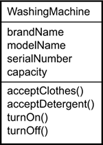
You'll also see that things naturally fall into categories (automobiles, furniture, washing machines. . . ). We refer to these categories as classes. A class is a category or group of things that have the same attributes and the same behaviors. Here's an example. Anything in the class of washing machines has attributes such as brand name, model, serial number, and capacity. Behaviors for things in this class include the operations “accept clothes,” “accept detergent,” “turn on,” and “turn off.”
Figure 1.1 shows an example of the UML notation that captures these attributes and behaviors of a washing machine. A rectangle is the icon that represents the class. It's divided into three areas. The uppermost area contains the name, the middle area holds the attributes, and the lowest area holds the operations.
Notice the spacing in the names of the class, the attributes, and the operations. In UML, a multiword classname has initial capital letters for all the words and eliminates whitespace between each word (for example, WashingMachine). Attribute-names and operation-names follow the same convention, but the first letter of the first word isn't capitalized (for example, acceptClothes()). A pair of parentheses follows the name of each operation—for reasons we'll get into in Hour 3.
As you'll see in Hour 4, a class diagram consists of a number of these rectangle icons connected by lines that show how the classes relate to one another.
Why bother to think about classes of things and their attributes and behaviors? In order to interact with our complex world, most modern software simulates some aspect of the world. Decades of experience suggest that it's easiest to develop software that does this when the software represents classes of real-world things. Class diagrams provide the representations that developers work from.
Class diagrams help on the analysis side, too. They enable analysts to talk to clients in the clients' terminology and thus stimulate the clients to reveal important details about the problem they want solved.
An object is an instance of a class—a specific thing that has specific values of the class's attributes. Your washer, for example, might have the brand name Laundatorium, the model name Washmeister, a serial number of GL57774, and a capacity of 16 pounds.
The icons in Figure 1.2 show how the UML represents an object. Note that the icon is a rectangle, just like the class icon, but the name is underlined. In the icon on the left, the name of the specific instance is on the left side of a colon, and the name of the class is on the right side of the colon. The name of the instance begins with a lowercase letter. It's also possible to have an anonymous object, as the icon on the right of Figure 1.2 shows. This just means that you don't supply a specific name for the object, although you do show the class it belongs to.
A use case is a description of a system's behavior from a user's standpoint. For system developers, the use case is a valuable tool: It's a tried-and-true technique for gathering system requirements from a user's point of view. Obtaining information from the user's point of view is important if the goal is to build a system that real people (and not just computerphiles) can use.
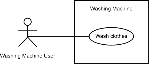
We'll discuss use cases in greater detail in Hours 6, “Introducing Use Cases”; 7, “Working with Use Case Diagrams”; 18, “Gathering System Requirements”; and 19, “Developing the Use Cases.” For now, here's a quick example. You use a washing machine, obviously, to wash your clothes. Figure 1.3 shows how you'd represent this in a UML use case diagram.
The little stick figure that corresponds to the washing machine user is called an actor. The ellipse represents the use case. Note that the actor—the entity that initiates the use case—can be a person or another system. Note also that the use case is inside a rectangle that represents the system, and the actor is outside the rectangle.
At any given time, an object is in a particular state. A person can be a newborn, infant, child, adolescent, teenager, or adult. An elevator is either moving or stationary. A washing machine can be either in the soaking, washing, rinsing, spinning, or off state.
The UML state diagram shown in Figure 1.4 captures this bit of reality. The figure shows that the washing machine transitions from one state to the next.
The symbol at the top of the figure represents the start state and the symbol at the bottom represents the end state.
Class diagrams and object diagrams represent static information. In a functioning system, however, objects interact with one another, and these interactions occur over time. The UML sequence diagram shows the time-based dynamics of the interaction.
Continuing with the washing machine example, the components of the machine include a timer, a water pipe (for fresh water input), and a drum (the part that holds the clothes and the water). These, of course, are also objects. (As you'll see, an object can consist of other objects.)
What happens when you invoke the “Wash clothes” use case? Assuming you've completed the “add clothes,” “add detergent,” and “turn on” operations, the sequence of steps goes something like this:
At the beginning of “Soaking,” water enters the drum via the water pipe.
The drum remains stationary for 5 minutes.
At the end of “Soaking,” water stops entering the drum.
At the beginning of “Washing,” the drum rotates back and forth and continues doing this for 15 minutes.
At the end of “Washing,” the drum pumps out the soapy water.
The drum stops rotating.
At the beginning of “Rinsing,” water entry restarts.
The drum rotates back and forth.
After 15 minutes water entry stops.
At the end of “Rinsing,” the drum pumps out the rinse water.
The drum stops rotating.
At the beginning of “Spinning,” the drum rotates clockwise and continues for 5 minutes.
At the end of “Spinning,” the drum rotation stops.
The wash is done.
Imagine that the timer, the water pipe, and the drum are objects. Assume that each object has one or more operations. The objects work together by sending messages to each other. Each message is a request from the sender-object to the receiver-object. The request asks the receiver to complete one of its (the receiver's) operations.
Let's get specific about the operations. The timer can
Time the soaking
Time the washing
Time the rinsing
Time the spinning
The water pipe can
Start a flow
Stop a flow
The drum can
Store water
Rotate back and forth
Rotate clockwise
Stop rotating
Pump water
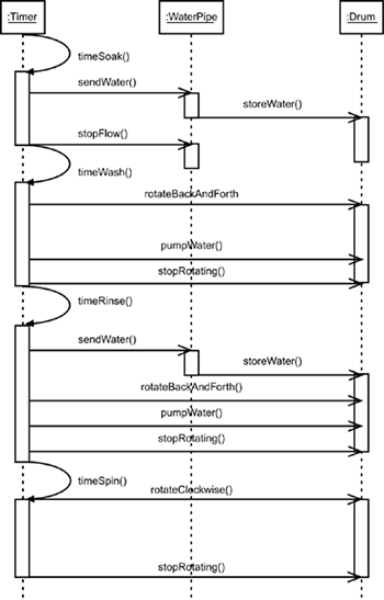
Figure 1.5 shows how to use these operations to create a sequence diagram that captures the messages among the timer, water pipe, drum, and drain represented as anonymous objects at the top of the diagram. Each arrow represents a message that goes from one object to another. Time, in this diagram, proceeds from top to bottom. So the first message is timeSoak(), which the timer sends to itself. The second message is sendWater(), which the timer sends to the water pipe. The final message, stopRotating(), goes from the timer to the drum.
Notice that an object (in this case, the timer) can send a message to itself. Notice also that the arrowheads do not all have the same shape. You'll learn more about that in Hour 9, “Working with Sequence Diagrams.”
Note: If you don't remember what an anonymous object is, go back and look at Figure 1.2.
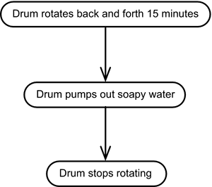
The activities that occur within a use case or within an object's behavior typically occur in a sequence, as in the steps listed in the preceding subsection. Figure 1.6 shows how the UML activity diagram represents steps 4 through 6 of that sequence.
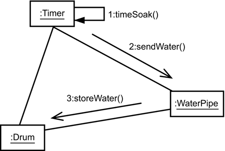
The elements of a system work together to accomplish the system's objectives, and a modeling language must have a way of representing this. The aforementioned sequence diagram does this. The UML communication diagram shown in Figure 1.7 also does this, but in a slightly different way. Rather than show you the communication diagram that's equivalent to the sequence diagram in Figure 1.5, Figure 1.7 shows you one that captures just the first few messages among the timer, the water pipe, and the drum. Rather than represent time in the vertical dimension, this diagram shows the order of messages by attaching a number to the message label.
Both the sequence diagram and the communication diagram show interactions among objects. For this reason, the UML refers to them collectively as interaction diagrams.
This diagram and the next one move away from the world of washing machines because the component diagram and the deployment diagram are geared expressly toward computer systems.
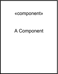
Modern software development proceeds via components, which is particularly important in team-based development efforts. Without elaborating too much at this point, Figure 1.8 shows how the UML version 1.x represents a software component.
Here's where UML 2.0 makes an entrance. In response to the many modelers who felt this symbol was awkward, UML 2.0 provides a revised symbol. Figure 1.9 shows the new way to represent a software component.
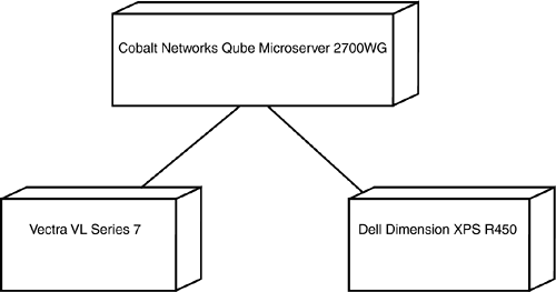
The UML deployment diagram shows the physical architecture of a computer-based system. It can depict the computers, show their connections with one another, and show the software that sits on each machine. Each computer is represented as a cube, with interconnections between computers drawn as lines connecting the cubes. Figure 1.10 presents an example.
Earlier I mentioned that the UML provides features that enable you to extend the diagrams. This section describes a couple of prominent ones.
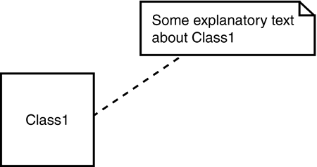
It often happens that one part of a diagram doesn't present an unambiguous explanation of why it's there or how to work with it. When that's the case, the UML note is helpful. Think of a note as the graphic equivalent of a yellow sticky. Its icon is a rectangle with a folded corner. Inside the rectangle is explanatory text. Figure 1.11 shows an example. You attach the note to a diagram element by connecting a dashed line from the element to the note.
The UML provides a number of useful items, but it's not an exhaustive set. Every now and then you'll create a model that requires some new concepts and new symbols. Stereotypes enable you to create new UML elements by basing them on existing elements. It's sort of like buying a suit off the rack and having it altered to fit your particular measurements (as opposed to creating one out of a bolt of cloth). Think of a stereotype as just this kind of alteration. You represent it as a name enclosed in two pairs of angle brackets called guillemets, and then you add that name to a UML symbol. The guillemet-enclosed name is called a keyword.
Sometimes the UML does this for you. Rather than create an entirely new symbol for something, the UML adds a keyword to an existing element. The keyword indicates that the element is used in a somewhat different way than originally intended. The concept of an interface (which you'll read about at length in Hour 5, “Understanding Aggregations, Composites, Interfaces, and Realizations”) provides a good example. An interface is a class that just has operations and has no attributes. It's a set of behaviors you might want to use again and again throughout your model (for reasons that become clearer in Hour 5). Instead of inventing a new element to represent an interface, UML uses a class icon with the keyword «Interface» situated just above the classname. (See Figure 1.12.)

Figure 1.12. A stereotype is an existing UML element with the addition of a keyword in guillemets. The keyword indicates that the element is used in a somewhat different way than originally intended.
The stereotype concept is particularly useful when you use a UML modeling tool. One important feature of a modeling tool is a “dictionary” that keeps track of all the elements you create in your model—classes, use cases, components, and others. (“Dictionary” is my own term. Different tools call it different names.) The dictionary can only work with existing UML elements and with stereotypes based on these elements. Thus, stereotyping allows you to create something new and store it in the dictionary. This is important because the dictionary helps you organize and manage your model and enables you to reuse the elements you create.
In Hour 14, “Understanding Packages and Foundations,” I look under the hood of the UML and examine the foundations of concepts like the stereotype. For now just bear in mind that to visualize a stereotype you add a keyword to a UML icon. Also bear in mind that as you work with UML (particularly if you work with a UML modeling tool), you'll find that UML comes with some built-in stereotypes and predefined keywords (like «component» and «Interface»).
In addition to new takes on UML 1.x diagrams (like the software component icon), UML 2.0 adds some new ideas to the mix.
When you're modeling a class, you might find it useful to show something about the class's internal structure. This often happens if the class consists of component classes.
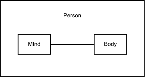
For example, let's assume that a person consists of a mind and a body. In Hour 5 you'll see the traditional way of modeling that statement. It consists of lines and symbols that join the Person class to the Mind class and to the Body class.
With UML 2.0's composite structure diagram you add a dimension. You put each component class inside the whole. This conveys the idea that you're looking inside the class into its structure. Figure 1.13 shows you what I mean.
Version 1.x allowed this kind of notation in class diagrams. Version 2.0 explicitly identifies this technique as its own kind of diagram.
Consider once again the activity diagram (Figure 1.6). This shows you a series of steps, that is, “activities.” Suppose each of those activities involves a sequence of messages among objects. If you replaced some of the activities with sequence diagrams or communication diagrams (or a combination of the two), you'd have UML 2.0's new interaction overview diagram.
Here's an example. Imagine you're at a library.
You find a book in the library's database.
You bring the book to the circulation desk to borrow the book.
A guard at the exit verifies that you checked out the book before you can leave the library with it.
Figure 1.14 shows a simple activity diagram that captures these three steps.
Now let's analyze each activity. In the first one, you ask the library database to locate the book, and the database responds by telling you to go to the book's location. In the second, you ask the librarian to check the book out to you, and after the checkout, the librarian tells you to take the book. In the third, you can leave the library only if a guard verifies that you have checked out the book.
Figure 1.15 shows how to organize all this in sequence diagrams taken in . . . well . . . sequence.
Think back to the examples involving the washing machine. I used this venerable appliance to discuss diagrams for classes, states, sequences, and communications.
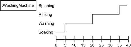
In the part about sequence diagrams, I mentioned the duration of each state—5 minutes for soaking, 15 minutes for washing, 15 minutes for rinsing, and 5 minutes for spinning.
If you carefully examine the sequence diagram in Figure 1.5, you'll see that it never explicitly shows these durations. UML 2.0's timing diagram handles this. It's designed to show how long an object is in a state. Figure 1.16 shows one form of this new diagram.
Version 1.x includes a capability for organizing the elements of a diagram. Dubbed a package, its icon is a tabbed folder, as in Figure 1.17. The idea is to put elements that go together inside one of these tabbed folder icons. For example, if a number of classes or components constitute a particular subsystem, they would go into a package.
By specifying a package diagram, Version 2.0 gives a sort of promotion to the package. No longer considered just a way of organizing a diagram's elements, the package has attained diagram status of its own.
As you can see, the UML's diagrams make it possible to examine a system from a number of viewpoints. It's important to note that not all the diagrams must appear in every UML model. Most UML models, in fact, contain a subset of the diagrams I listed.
Why is it necessary to have numerous views of a system? Typically, a system has a number of different stakeholders—people who have interests in different aspects of the system. Let's return to the washing machine example. If you're designing a washing machine's motor, you have one view of the system. If you're writing the operating instructions, you have another. If you're designing the machine's overall shape, you see the system in a totally different way than if you just want to wash your clothes.
Conscientious system design involves all the possible viewpoints, and each UML diagram gives you a way of incorporating a particular view. The objective is to communicate clearly with every type of stakeholder.
Some might argue that UML modeling isn't very important. After all, isn't programming the most important part of the project? Don't developers do the “real” work while modelers just draw pictures?
To understand the importance of accurate visual modeling, consider a well-known, long-term construction project in Boston, Massachusetts. Formally known as the Central Artery/Tunnel, but more popularly known as “The Big Dig,” the goal of this project is to alleviate Boston's massive traffic crush: A system of tunnels and bridges through the center of the city will ultimately eliminate an aging, undersized, elevated highway. In addition to solving the traffic problem, the Big Dig will have major economic and environmental benefits.
Those benefits better be huge, because the project has generated cost overruns in excess of a billion dollars. According to a report in the Boston Globe, one reason is that the drawings (that is, the visual models) that guide excavation and construction were incomplete and inaccurate.
For example, the FleetCenter (Boston's sports and entertainment facility) was missing from one drawing. That glaring omission misled contractors into thinking they had an unobstructed path for laying utility lines in a particular area of the city. Another drawing showed a manhole (intended as a connection for electrical lines) that didn't exist. Still another drawing of one of the tunnels left a 4-foot gap between tunnel sections. Workers detected this gap only after the sections were in position.
The result was a lot of costly unforeseen work to correct the mistakes, along with numerous missed deadlines.
Sound familiar?
System development is a human activity. Without an easy-to-understand notation system, the development process has great potential for error.
The UML is a notation system that has become a standard in the system development world. It's the result of work done by Grady Booch, James Rumbaugh, and Ivar Jacobson. Consisting of a set of diagrams, the UML provides a standard that enables the system analyst to build a multifaceted blueprint that's comprehensible to clients, programmers, and everyone involved in the development process. It's necessary to have all these diagrams because each one speaks to a different stakeholder in the system.
A UML model tells what a system is supposed to do. It doesn't tell how the system is supposed to do it.
I've seen the Unified Modeling Language referred to as “UML” and also as “the UML.”Which is correct? | |
A1: | The creators of the language prefer “the UML.” |
You mentioned that object-oriented concepts play a major role in this book. Do I have to be a Java coder or a C++ developer in order to understand these concepts and to use them? | |
A2: | Absolutely not. Object-oriented concepts aren't just for programmers. They're extremely useful for system analysts who want to understand and model the area of knowledge their system works in. |
You've made the point that the UML is a great tool for analysts. The deployment diagram, however, doesn't seem like something that would be all that useful in the analysis stage of system development. Isn't it more appropriate for a later stage? | |
A3: | It's really never too early to start thinking about deployment (or other issues traditionally left for later in development, like system security). Although it's true that the analyst is concerned with talking to clients and users, early in the process an analyst might think about the computers and components that will make up the system hardware. Sometimes the client dictates this. Sometimes the client wants a recommendation from the development team. Certainly a system architect will find the deployment diagram useful. |
You mentioned that hybrid diagrams are possible. Does UML, excuse me, the UML impose limitations on which elements you can combine with which on a diagram? | |
A4: | No. The UML sets no limits. It's usually the case, however, that a diagram contains one kind of element. You could put class icons on a deployment diagram, but that might not be very useful. |
Figure 1.3 shows a use case diagram for “wash clothes.” All this says is that a washing machine user wants to wash clothes. Do we really need a set of symbols to say that? Can't we just say that in a simple sentence? | |
A5: | If that's all you had to say, then you're right: You could probably get away with just a sentence. In a typical development project, however, use cases are like “Tribbles” in the original Star Trek series (Episode 42). You start with a few, and before you know it. . . . |
You've jumped into the UML. Now it's time to firm up your knowledge of this great tool by answering some questions and going through some exercises. The answers appear in Appendix A, “Quiz Answers.”
Why is it necessary to have a variety of diagrams in a model of a system? | |
Which diagrams give a static view of a system? | |
Which diagrams provide a dynamic view of a system (that is, show change over time)? | |
What kinds of objects are in Figure 1.5? |
1: | Suppose you're building a computer-based system that plays chess with a user. Which UML diagrams would be useful in designing the system? Why? |
2: | For the system in the exercise you just completed, list the questions you would ask a potential user and why you would ask them. |
3: | Take a look at the communication diagram in Figure 1.7. How would you complete it so that it's equivalent to the sequence diagram in Figure 1.5? What problems do you run into? |
4: | Go back to the bulleted lists of operations for the objects in Figure 1.5. Consider each object to be an instance of a class. Draw a class diagram that includes these classes and these operations. Can you think of some additional operations for each class? |
5: | Take things a step further. Try to organize your classes in Exercise 4 into a composite structure diagram of a washing machine. Can you think of some additional component classes? |
6: | In the subsection on state diagrams, I said an elevator can be either moving or stationary. Although you don't know much about state diagrams yet, see if you can figure out how to represent the states of an elevator. In addition to the names of the states, what other information should the state diagram somehow show? (Hint: Account for the elevator door. When is it open? When is it closed?) |
7: | Look at the sequence diagram in Figure 1.5 and the sequence diagrams that make up the interaction overview diagram in Figure 1.15. Focus on the messages that go from one object to another. Try to think of what (if anything) might go inside the parentheses in each message. |
