What You'll Learn in This Hour:
How to represent a use case model
How to visualize relationships among use cases
How to create and apply use case models
The use case is a powerful concept for helping an analyst understand how a system should behave. It helps you gather requirements from the users' point of view. In this hour, you'll learn how to visualize the use case concepts you learned in the last hour.
As powerful as the use case concept is, use cases become even more powerful when you use the UML to visualize them. Visualization allows you to show use cases to users so they can give you additional information. It's a fact of life that users often know more than they can articulate: The use case helps break the ice. Also, a visual representation allows you to combine use case diagrams with other kinds of diagrams.
One of the objectives of the system analysis process is to generate a collection of use cases. The idea is to be able to catalog and reference this collection, which serves as the users' view of the system. When it's time to upgrade the system, the use case catalog serves as a basis for gathering the requirements of the upgrade.
An actor initiates a use case, and an actor (possibly the initiator, but not necessarily) receives something of value from the use case. The graphic representation is straightforward: An ellipse represents a use case, and a stick figure represents an actor. The initiating actor is on the left of the use case, and the receiving actor is on the right. (Many modelers omit the receiving actor, and the UML 2.0 specification doesn't mention it.) The actor's name appears just below the actor. The name of the use case appears either inside the ellipse or just below it. An association line connects an actor to the use case, and represents communication between the actor and the use case. The association line is solid, like the line that connects associated classes.
One of the benefits of use case analysis is that it shows the boundary between the system and the outside world. Actors are typically outside the system, whereas use cases are inside. You use a rectangle (with the name of the system somewhere inside) to represent the system boundary. The rectangle encloses the system's use cases.
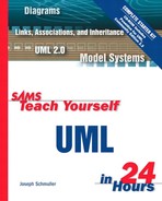
The actors, use cases, and interconnecting lines make up a use case model. Figure 7.1 shows the symbols.
Figure 7.1. In a use case model, a stick figure represents an actor, an ellipse represents a use case, and an association line represents communication between the actor and the use case.
Let's apply the symbols to the example from the previous hour. As you'll recall, you developed use cases for a soda machine. The “Buy soda” use case sits inside the system along with “Restock” and “Collect.” The actors are Customer, Supplier's Representative, and Collector. Figure 7.2 shows a UML use case model for the soda machine.

Each use case is a collection of scenarios, and each scenario is a sequence of steps. As you can see, those steps do not appear on the diagram. They're not in notes attached to the use cases. Although the UML doesn't prohibit this, clarity is key in creating any diagram and attaching notes to every use case would make the diagram too busy. How and where do you keep track of the steps?
Your use case diagrams will usually be part of a design document that the client and the development team refer to. Each diagram will have its own page. Each scenario of each use case will also have its own page, listing in text form
The actor who initiates the use case
Assumptions for the use case
Preconditions for the use case
Steps in the scenario
Postconditions when the scenario is complete
The actor who benefits from the use case
You can also include a brief, one-sentence description of the scenario. Note that this text page is outside the boundaries of the UML. Thus, the UML doesn't specify any particular format for this.
Hour 6, “Introducing Use Cases,” presented some alternative scenarios for the “Buy soda” use case. In your description, you can either list these scenarios separately (“Out-of-brand” and “Incorrect change”), or you can consider them exceptions to the first scenario in the use case. Exactly how you do all this is up to you, your client, and the users.
Another Possibility
To show the steps in a scenario, another possibility is to use a UML activity diagram (discussed in Hour 11, “Working with Activity Diagrams”).
The example in Hour 6 also showed two ways that use cases can relate to one another. One way, inclusion, enables you to reuse one use case's steps inside another use case. The other way, extension, allows you to create a new use case by adding steps to an existing use case.
Two other kinds of relationships are generalization and grouping. As is the case for classes, generalization has one use case inheriting from another. Grouping is a simple way of organizing a set of use cases.
Let's examine the “Restock” and “Collect” use cases from the Hour 6 example. Both begin with unsecuring the machine and pulling it open, and both end with closing the machine and securing it. The “Expose the inside” use case was created to capture the first pair of steps, and the “Unexpose the inside” use case to capture the second. Both “Restock” and “Collect” include these two use cases.
To represent inclusion, you use the symbol you used for dependency between classes—a dashed line connecting the classes with an arrowhead pointing to the depended-on class. Near the line, you add the keyword «include». Figure 7.3 shows the inclusion relationship in the use case model of the soda machine.
In the text notation that tracks the steps in the sequence, you indicate the included use cases. The first step in the “Restock” use case would be «include» (expose the inside).
Hour 6 showed that the “Restock” use case could be the basis of another use case: “Restock according to sales.” Instead of just restocking the soda machine so that all brands end up with the same number of cans, the supplier's representative could take note of the brands that sold well and the brands that did not, and restock accordingly. The new use case is said to extend the original one because it adds new steps to the sequence in the original use case, also called the base use case.
Extension can only take place at specific designated points within the base use case's sequence. These points are called, appropriately, extension points. In the “Restock” use case, the new steps (noting the sales and designating the appropriate refills) would occur before the supplier's representative opened the machine and was ready to fill the compartments of the soda brands. For this example, the extension point is “before filling the compartments.”
Like inclusion, you visualize extension with a dependency line (dashed line and arrowhead) along with a keyword. In this case the keyword is «extend». Within the base use case, the extension point appears in a compartment named “extension point” (or “extension points” if you have more than one) below the name of the use case. Figure 7.4 shows the extension relationship for “Restock” and “Restock according to sales” along with the inclusion relationships for “Restock” and “Collect.”
It's important to be aware that the locations of the use cases in the use case diagram don't signify anything. In Figure 7.4, for example, “Expose the inside” is above “Unexpose the inside.” This does not mean that “Expose the inside” precedes “Unexpose the inside.” Common sense tells you that it does, but the use case diagram doesn't take that into account.
Some have tried to number the use cases in order to show their order. This is way more trouble than it's worth, particularly when a use case is included in several others. If it's included in Use Case 3 and Use Case 4, is it Use Case 3.1? Or is it 4.1? Suppose it's the first included use case in Use Case 3, but the second in Use Case 4. Then what?
It's best to understand that the intent of the use case diagram is to show what the use cases are without specifying their order of occurrence. (In that spirit, see the accompanying sidebar “Extension, Inclusion, and Confusion.”)
Extension, Inclusion, and Confusion
In my experience, people who are used to modeling process flows (from pre-UML times) are sometimes confused by the direction of dependency arrows. The confusion often emerges when it comes to modeling extension and inclusion of use cases. This happens because process-flow veterans are used to seeing arrows that denote sequences of operations or activities: The first one in a sequence connects with the second one via an arrow that points from the first to the second.
Thus in a use case diagram that shows Use Case A including Use Case B, their tendency is to think that Use Case A takes place first, followed immediately by Use Case B. Many times—by the nature of inclusion—the opposite turns out to be true.
The key is to bear in mind that a dependency arrow doesn't specify the direction of a process. Instead, it specifies the direction of a relationship. A dependency arrow that starts at Use Case A and ends at Use Case B means that A depends on B, not that A precedes B.
Classes can inherit from one another, and so can use cases. In use case inheritance, the child use case inherits behavior and meaning from the parent and adds its own behavior. You can apply the child wherever you apply the parent.
Suppose you're modeling a soda machine that allows a customer to buy either a can of soda or a cup of soda. In that case, “Buy soda” would be a parent use case, and “Buy a can of soda” and “Buy a cup of soda” would be child use cases. You model generalization of use cases the same way you model generalization of classes—with a solid line that has an open triangle pointing at the parent, as in Figure 7.5.
The generalization relationship can exist between actors, too. You might have represented both the supplier's representative and the collector as agents of the supplier. If you rename the representative as the Restocker, the Restocker and Collector are both children of the Supplier Agent, as Figure 7.6 shows.
In some use case diagrams, you might have a multitude of use cases and you'll want to organize them. This could happen when a system consists of a number of subsystems. Another possibility is when you're interviewing users in order to gather requirements for a system. Each requirement would be represented as a separate use case. You'll need some way of categorizing the requirements.
The most straightforward way to organize is to group related use cases into a package. A package, remember, appears as a tabbed folder. The grouped use cases appear inside the folder.
Given the example you worked with, you dived right in and applied the use case symbols. Now it's time to step back and put use cases in the context of an analysis effort.
Client interviews should start the process. These interviews will yield class diagrams that serve as the foundation for your knowledge of the system's domain (the area in which it will solve problems). After you know the general terminology of the client's area, you're ready to start talking to users.
Interviews with users begin in the terminology of the domain but should then shift into the terminology of the users. The initial results of the interviews should reveal actors and high-level use cases that describe functional requirements in general terms. This information provides the boundaries and scope of the system.
Later interviews with users delve into these requirements more closely, resulting in use case models that show the scenarios and sequences in detail. This might result in additional use cases that satisfy inclusion and extension relationships. In this phase it's important to rely on your understanding of the domain (from the class diagrams derived from client interviews). If you don't understand the domain well, you might create too many use cases and too much detail—a situation that could greatly impede design and development.
To further your understanding of use case models and how to apply them, let's take a look at a more complex example than a soda machine. Suppose you have to design a local area network (LAN) for a consulting firm, and you have to figure out the functionality to build into the LAN. How do you start?
Exactly What Is a LAN?
A LAN is a communication network that an organization uses over a limited distance. It allows users to share resources and information.
Begin with client interviews to create a class diagram that reflects what life is like in the world of consulting. The class diagram might include these classes: Consultant, Client, Project, Proposal, Data, and Report. Figure 7.7 shows what the diagram might look like.

Now that the domain is in hand, turn your attention to the users, because the objective is to figure out the kinds of functionality to build into the system.
In the real world, you would interview users. For this example you'll base your ideas on some general knowledge about LANs and about the domain. Bear in mind, however, that in real-world systems analysis, nothing can substitute for interviews with real people.
One group of users will be consultants. Another will be clerical staff. Other potential users include corporate officers, marketers, network administrators, office managers, and project managers. (Can you think of any others?)
At this point, it's helpful to show the users in a generalization hierarchy, as in Figure 7.8.
What about the use cases? Here are some possibilities: “Provide security levels,” “Create a proposal,” “Store a proposal,” “Use e-mail,” “Share database information,” “Perform accounting,” “Connect to the LAN from outside the LAN,” “Connect to the Internet,” “Share database information,” “Catalog proposals,” “Use prior proposals,” and “Share printers.” Based on this information, Figure 7.9 shows the high-level use case diagram that we build.
This set of use cases constitutes the functional requirements for the LAN.
Let's elaborate on one of the high-level use cases and build a use case model. One extremely important activity in a consulting firm is writing proposals, so let's examine the “Create a proposal” use case.
Interviews with consultants would probably tell you that a number of steps are involved in this use case. First of all, the initiating actor is a consultant. The consultant has to log on to the LAN and be verified as a valid user. Then he or she has to use office suite software (word processing, spreadsheet, and graphics) to write the proposal. In the process, the consultant might reuse portions of prior proposals. The consulting firm might have a policy that one corporate officer and two other consultants review a proposal before it goes to a client. To satisfy this policy, the consultant stores the proposal in a central repository accessible to the LAN and e-mails the three reviewers with a message telling them that the proposal is ready and informing them of its location. After receiving feedback and making necessary modifications (again, using the office suite software), the consultant prints out the proposal and mails it to the client. When everything's finished, the consultant logs off the network. The consultant has completed a proposal, and is the actor who benefits from the use case.
Business Logic
When an interview reveals something like that “three reviewers” policy I just mentioned, take careful note. It means that you're starting to hear about a company's business logic—its set of rules for how it conducts itself. The more business logic you can find out, the better off you'll be as an analyst. You'll understand your client's corporate culture, and you'll be better able to understand organizational needs.
From the preceding sequence, it's clear some of the steps will be repeated from one use case to another, and thus lead to other (possibly included) use cases you might not have thought of before. Logging on and getting verified are two steps that numerous use cases can include. For this reason, you'd create a “Verify user” use case that “Create a proposal” includes. Two other included use cases are “Use office suite software” and “Log off the network.”
Additional thought about the proposal process might make you realize that the proposals written for new clients differ from the proposals written for existing clients. In fact, new-client proposals probably provide promotional information about the firm. This information usually precedes the statement of the problem. With existing clients, it's not necessary to send that kind of information. Thus, another new use case, “Create a proposal for a new client” extends “Create a proposal.”
Figure 7.10 shows the use case diagram that results from this analysis of the “Create a proposal” use case.
This example brings home an important point—a point that was stressed before: The use case analysis describes the behavior of a system. It doesn't touch the implementation. This is particularly important here because the design of a LAN is far beyond the scope of this book!
This is a good time to look at the overall structure of the UML because you've gone through two of its major aspects—object orientation and use case analysis. You've seen their foundations and symbols, and you've explored some applications.
Classes
Objects
Interfaces
Use cases
Actors
Associations
Generalizations
Dependencies
Realizations
Aggregations
Composites
Stereotypes
Constraints
Notes
Packages
Extensions
Inclusions
Let's try to partition this set of items into categories.
Classes, objects, actors, interfaces, and use cases are five of the structural elements in the UML. Although they have a number of differences (which, as an exercise, you ought to enumerate), they are similar in that they represent either physical or conceptual parts of a model. As you proceed through Part I, you'll encounter additional structural elements.
Associations, generalizations, dependencies, aggregations, composites, and realizations are the relationships in the UML. (Inclusion and extension are two kinds of dependencies.) Without relationships, UML models would just be lists of structural elements. The relationships connect those elements and thereby connect the models to reality.
The package is the only grouping element in the UML. It allows you to organize the structural elements in a model. A package can hold any kind of structural element and can hold many different kinds at once.
The note is the UML's annotation element. Notes enable you to attach constraints, comments, requirements, and explanatory graphics to your models.
Stereotypes and constraints are two constructs the UML provides for extending the language. They allow you to create new elements out of existing ones, so that you can adequately model the slice of reality your system will play in.
In addition to structural elements, relationships, grouping, annotation, and extension, the UML has another category—behavioral elements. These elements show how parts of a model (such as objects) change over time. You haven't dealt with these yet, but you will learn about one in the next hour.
Now you have an idea of how the UML is organized. Figure 7.11 visualizes this organization for you. As you go through the remaining hours in Part I, keep this organization in mind. You'll keep adding to it as you go along, and this “big picture” will show you where to add the new knowledge you acquire.

The use case is a powerful tool for gathering functional requirements. Use case diagrams add still more power: Because they visualize use cases, they facilitate communication between analysts and users as well as between analysts and clients. In a use case diagram, the symbol for a use case is an ellipse. The symbol for an actor is a stick figure. An association line joins an actor to a use case. The use cases are usually inside a rectangle that represents the system boundary.
Inclusion is represented by a dependency line with the keyword «includes». Extension is represented by a dependency line with the keyword «extends». Two other relationships between use cases are generalization, in which one use case inherits the meaning and behaviors of another, and grouping, which organizes a set of use cases. Generalization is represented by the same generalization line that shows inheritance among classes. Grouping is represented by the package icon.
Use case diagrams figure heavily into the analysis process. Begin with client interviews that yield class diagrams. The class diagrams provide a foundation for interviewing users. User interviews result in a high-level use case diagram that shows the functional requirements of the system. To create use case models, drill down into each high-level use case. The resulting use case diagrams provide the foundation for design and development.
Object orientation and use cases are the two heavyweight concepts behind the UML. Now that you've seen them, you're ready for the big picture of the UML. The elements you've learned about in Hours 2–7 fall into these categories: structural elements, relationships, organization, annotation, and extension. In the next hour, you'll learn about an element in the remaining category: behavioral elements. Keeping this big picture in mind will help you as you learn more about the UML.
In this workshop, you'll continue with the knowledge you gained in Hour 6, using it as a foundation for the knowledge from this hour. The objective is to use your new knowledge to visualize use cases and their relationships. The answers appear in Appendix A, “Quiz Answers.”
1: | Sketch the diagram of a use case model for a TV remote control. Be sure to include all the functions of the remote as use cases for your model. |
2: | In the fourth exercise in Hour 6, you listed the actors and use cases for a computer superstore. This time, draw a high-level use case diagram based on the work you did for that exercise. Then create a use case model for at least one of the high-level use cases. In your work, try to incorporate the includes or extends relationships. |
3: | Consider what happens when you go shopping for groceries and other necessities in a supermarket. Create the concept for a device that eliminates some of the annoyances associated with this experience and model the use cases for that device. In your set of use cases, use inclusion, extension, and generalization wherever they're appropriate. |