
What You'll Learn in This Hour:
Listing the working parts of the system
Analyzing interactions among the working parts
Modifying use cases
The use-case analysis in the last hour goes a long way toward making the WIN system a reality. The analysis still isn't far enough along to begin coding the system, however.
Analyzing the use cases has helped conceptualize the working parts of the system. Although you now know a lot about the use cases, you still have to model how those working parts will interact with one another and how (and when) they change state. Passing this information to the programmers will make their jobs a lot easier. They will have a clearer vision of how to code classes and make them work together.
One way to start is to enumerate the system components suggested in each package of use cases. Although you didn't explicitly analyze all the use cases in all the packages in the last hour, you can still extract the system components those use cases assume. In a real development effort, of course, a development team would have analyzed all the use cases before moving on.
At the end of the last hour, you enumerated the software parts of the system based on your analysis of the first nine use cases in the Server package: On the handheld PCs, WIN will need user interface screens for order entry, order change, order-status tracking, customer status, and message sending. A user interface main screen will also be necessary. Your analysis revealed the need for an order-tracking user interface screen on the kitchen PC. WIN will require a database to hold all the orders.
In addition, the use cases you didn't analyze might suggest other system components. To refresh your memory, those use cases were
Summon a busser
Take a drink order
Transmit drink order to lounge
Receive acknowledgment
Receive notification from lounge
Receive notification from kitchen
The use cases suggest some straightforward components. The first one tells you something in the Server's user interface (like a dedicated screen) has to enable the server to summon a busser. The second tells you that a screen is necessary for taking a drink order (analogous to the screen for taking a meal order). The user interface has to be able to receive an acknowledgment (to show, for example, that a busser has received a request) and to receive a message from the lounge that a drink is ready.
Given the job of a server, it's not surprising that the main components in this package are user interface screens concerned with order taking and with message sending and receiving.
The use cases in the Chef package are
Store a recipe
Retrieve a recipe
Notify the server
Receive a request from the server
Acknowledge server request
Enter the preparation time
Assign an order
What components do these use cases suggest? Again, they follow in a straightforward manner.
The use cases for the Busser are
Receive a request from the server
Acknowledge a request
Signal table serviced
As you'll recall, in the last hour you split the Assistant package into Assistant Server and Assistant Chef. The use cases for the Assistant Server would be
Receive a request from the server
Acknowledge a request
Notify request completed
The use cases for the Assistant Chef would be
Receive a request from the chef
Acknowledge a request
Notify request completed
One might argue that a separate computer for an assistant chef isn't necessary because he or she works in close proximity with a chef in the kitchen. If the kitchen is very large, however, electronic communication might be a good idea.
The use cases for the Bartender are
Enter a drink recipe
Retrieve a drink recipe
Receive notification from the server
Receive a request from the server
Acknowledge a request
Notify request completed
These use cases are analogous to the Chef package's use cases, and the software components they suggest are analogous to the Chef's components. The hardware is analogous, too: Behind a bar, a desktop would make more sense than a handheld would.
You'll need a database of drink recipes and user interface screens that allow easy access to this database for entering and retrieving a recipe. The bartender's user interface has to show a notification from a server (that a customer's table is ready) and a request from a server for a drink. The bartender has to be able to send an acknowledgment that a request was received and also to notify the server that a drink is ready.
The Coat-Check Clerk's use cases are
Print a coat check
Print a hat check
The software components in the coat-check clerk's handheld should include a user interface screen that enables him or her to print the appropriate check. The check should include the time and a description of the article. You will probably also want the system to have a database of checked items.
At this point in the project, the task is to show how the system components interact in order to complete each use case. (Remember what I said earlier: Behind every use case lurks a sequence diagram.) You'll model the interactions for a couple of the use cases in the Server package. The set of use cases is too big for you to look at all of them. In a real-world project, however, a development team does just that.
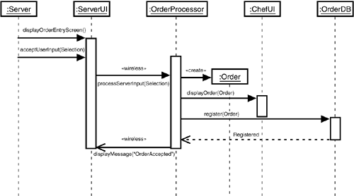
Start with the “Take an order” use case. From Hour 19, “Developing the Use Cases,” the steps are
On the handheld computer, the server activates the user interface for order entry.
The order entry user interface appears.
The server enters the customer's menu selection into WIN.
The system transmits the order to the kitchen PC.
In the model you developed in the last hour, this use case includes the “Transmit the order to the kitchen” use case, whose steps are
A button-click in the order user interface indicates “Send to kitchen.”
WIN transmits the order over the wireless LAN.
The order arrives in the kitchen.
The order-entry user interface on the handheld indicates that the order arrived in the kitchen.
A sequence diagram will show this interaction nicely. (So will a collaboration diagram, which I ask you to create in Exercise 1.) Preparing the diagram forces you to focus your thinking in several ways.
First, when the server takes the customer's order, the server, in effect, creates something—an order! That order is an object in the WIN system. (It's also an instance of a class, Order, from your domain analysis in Hour 17, “Performing a Domain Analysis.”) The chef will use it as a guideline for initiating and carrying out a set of actions. The server will total up a check that corresponds to it. The customer will pay the check. This created order, then, is an important item.
Also, if you examine the use cases “Change an order” and “Track order status” (as you will in a moment), you'll see references to a list of orders. This list has to come out of a database of orders—a database I alluded to at the end of Hour 19. It has to get into that database in the course of this use case. Remember also that the order processor operates behind the scenes.
You can focus your thinking in still another way. In the included use case, the term “kitchen” is a little vague. Because you're modeling software components, you have to refine what you mean here. Envisioning how this all might work leads one in a common-sense way to conclude that the order must somehow show up in the chef's user interface in the kitchen PC. How it does that is not your concern at this point, of course.
After you think these ideas through, the “Take an order” use case looks something like this:
On the handheld computer, the server activates the user interface for order entry.
The order entry screen appears.
The server enters the customer's menu selection into the order entry screen.
The order processor creates an order.
The order processor transmits the order to the chef's interface.
The order processor enters the order into the database of orders.
The order processor lets the server know that the order has been sent to the kitchen and that it's registered in the database of orders.
To create the sequence diagram that captures your thinking for this use case, you'll build on the class model at the end of Hour 19. The operations of the classes in that model are the set of messages you can include in your sequence diagram.
Figure 20.1 shows the sequence diagram. Just to recap what you learned earlier about sequence diagrams, the objects laid across the top of the diagram represent the components in this use case. The dashed line descending from each object is that object's lifeline, and time proceeds vertically downward. The little rectangles on the lifelines are called activations. Each activation represents the period of time during which an object is performing an action. An arrow from one lifeline to another represents a message that goes from one object to another. The type of arrowhead denotes the type of message. The Order object is created during this use case. For that reason, it's lower than the other objects, and the message pointing to it has a «create» stereotype.
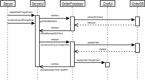
Here's another one. From the last hour, the steps in the “Change an order” use case are
On the handheld computer, the server activates the user interface screen for changing an order.
The user interface brings up a list of existing orders in the kitchen placed by this server.
The server selects the order to be changed.
The server enters the modification to the order.
The order processor transmits the updated order to the kitchen PC.
Again, preparing the diagram helps you refine your thinking and modify the use case slightly. After step 5, the system should enter the modified order into the database of orders.
The new use case should thus be
On the handheld computer, the server activates the user interface screen for changing an order.
The user interface brings up a list of existing orders in the kitchen placed by this server.
The server selects the order to be changed.
The server enters the modification to the order.
The order processor transmits the updated order to the kitchen PC.
The order processor enters the new order into the database of orders.
Figure 20.2 shows the sequence diagram that corresponds to this use case.
Try one more case before you finish. As you read in Hour 19, the “Track order status” use case consists of these steps:
On the handheld computer, the server activates the user interface screen for tracking an order entry.
The user interface brings up a list of existing orders in the kitchen placed by this server.
The server selects the order to be tracked.
The system transmits a tracking message to the kitchen PC.
The kitchen PC receives the message.
The chef brings up the tracking order interface on the kitchen PC.
The chef enters a time estimate for the order's completion.
The system transmits the time estimate back to the server's handheld.
As you work through this, you might decide that the tracking message to the kitchen PC (that is, to the chef's user interface) could be to display the order-tracking screen with the desired order highlighted. That would eliminate the need for step 6. Also, you would replace “system” (the term in your original use case) with “order processor.”
Finally, you might want to interview a few chefs and ask how they come up with the time estimate in step 7. Perhaps you can develop a software package that would help.
Figure 20.3 does the honors for this use case.

Seeing all the results so far, Messrs. LaHudra, Nar, and Goniff are ecstatic.
“This is going to change the entire nature of the restaurant business,” said Nar.
“I agree we're onto something,” said LaHudra, “but what do you mean 'change the entire nature of the restaurant business'?”
“Yes, what do you mean?” asked Goniff.
“Well, if you think about it,” Nar continued, “the whole job of the server is going to change, and so is the job of the chef. The servers won't be running around as much as they do now. They'll be information resources for the customers because they'll always be in their designated serving areas. They'll go to the kitchen and the bar only when they have to. Through their handheld computers, they'll become monitors of the order-preparation process and managers of their areas. They'll be more like lifeguards than traditional waiters. In fact, they'll be able to actually sit down while they work in their areas because work won't involve running around so much anymore.”
“And the chefs?”
“They'll become more managerial, too. They'll use their computers to assign orders to assistant chefs and coordinate what goes on in a kitchen. This will be great for large kitchens and large restaurants, now that we're moving information around instead of people.”
“Hmmm . . . That has a nice ring to it,” said LaHudra. “Apparently, when you move information more, you can get away with moving people less. Not bad.”
“Not bad at all,” said Goniff, already plotting the next expansion of the business.
After the use case analysis, a development team turns its attention to the system components the use cases suggest. What are they? How do they interact? This hour showed how to answer these questions in the context of developing the WIN system.
The objective of this effort is to provide information to the programmers—information that facilitates their efforts. The results of this analysis should make it easy for programmers to code the system objects and the ways those objects communicate with one another.
After you model interaction among components, the system is much closer to becoming a reality. As you model the interactions, you may find that it's appropriate to modify the use cases at the base of these interactions.
Here's where you get your chance to spread your wings on modeling interactions among system components. After you have answered the questions, interact with Appendix A, “Quiz Answers,” to find the answers. Incidentally, you might want to use the components listed in this hour to help you go above and beyond the listed exercises and make additional sequence diagrams and collaboration diagrams.
1: | Develop a collaboration diagram equivalent to the sequence diagram for the Server, use case “Take an order.” |
2: | Create a sequence diagram for the use case “Take a drink order.” |
3: | Select at least one use case in the Chef package and develop a sequence diagram. Use the list of components mentioned in this hour. Are any additional ones necessary? |
4: | Use your imagination on this one: The use cases in the Coat-Check Clerk package seem pretty simple. Can you embellish each one by adding a step or two? Would any additional components be helpful? Draw a sequence diagram for one of these use cases. |
5: | Take a look at the three sequence diagrams. Do you see any repetitions from one to another? If so, use the UML 2.0 techniques from Hour 9, “Working with Sequence Diagrams,” to reuse the repeated information from one diagram to another. |