What You'll Learn in This Hour:
Extensions for business
Lessons from the business extensions
Modeling GUIs
Modeling expert systems
Here we are in the final hour. It's been a long haul, but in the process you've seen a lot of the UML. In the last two hours, you've looked at applications in hot areas. In this hour, you'll wrap it all up with a current UML extension and a look at some other areas for applying the UML.
You read about UML extensions and profiles in Hour 14, “Understanding Packages and Foundations.” The goal of this hour is to start you thinking about how you would apply the UML in your domain and perhaps ultimately develop a domain-specific profile. Like any language, the UML is evolving. Its future depends on how modelers like you use and extend it.
One popular extension is a set of stereotypes designed to model a business. The stereotypes abstract some of the major ideas of what a business is all about. You can visualize them in terms of UML symbols you already know or as specialized icons (created by UML Amigo Ivar Jacobson). The intent is to model business-world situations rather than to serve as the basis for software construction.
Within a business, one obvious class is a worker. In the context of this UML extension, a worker acts within the business, interacts with other workers, and participates in use cases. A worker can be either an internal worker or a case worker. An internal worker interacts with other workers inside the business, and a case worker interacts with actors outside the business. An entity doesn't initiate any interactions, but it does participate in use cases. Workers interact with entities.
Figure 24.1 shows the customary UML notation for these stereotypes, along with the specialized icons. For each one, I've included an example from the restaurant domain.
The business extensions include two association stereotypes—communicates and subscribes. The first stereotype is for interactions between objects. The second describes an association between a source (called a subscriber) and a target (called a publisher). The source specifies a set of events. When one of those events occurs in the target, the source receives a notification.
Entities combine to form work units, which are task-oriented sets of objects. Work units, classes, and associations combine to form organization units. An organization unit, which can include other organization units, corresponds to an organization unit of the business.
By the way, for another take on UML extensions for modeling businesses and business processes, see Business Modeling with UML by Hans-Erik Eriksson and Magnus Penker (John Wiley & Sons, 2000).
The business extensions teach some valuable lessons. First, it's apparent that with a little imagination, it's possible to come up with simple icons and representations that capture fundamental aspects of a domain. The operative word is “simple.” Second, the representations help you think about, and create solutions in, a domain.
We'll consider these lessons as we try and move the UML into two important modeling efforts—graphic user interfaces and expert systems.
A hallmark of contemporary software packages, the graphic user interface (GUI) is here to stay. GRAPPLE and other development methodologies devote a JAD session to the development of an application's GUI.
In a design document, you typically include screen shots to show your client and your developers what the GUI will look like to the users. For several reasons, you still might want a specialized diagram to model a GUI.
The primary reason has to do with use cases. Like most parts of a development effort, GUI development is use case–driven. In fact, the GUI connects directly to use cases because it's the window (pardon the pun) through which the end-user initiates and completes use cases. It might be difficult to use screen shots to capture the relationship between screens and use cases.
Another reason is that you might want to capture the evolution in the thought process as the GUI takes shape. In GRAPPLE, GUI development starts when end-users participating in the JAD session manipulate post-it sticky notes (which represent onscreen controls) on large sheets of paper (which represent screens). It would be helpful to have a type of diagram that directly captures the results of these manipulations—one that a modeler could easily change when the JAD participants modify the design.
A diagram that shows the connections of the screens to the use cases will help the JAD participants remember what each screen is supposed to do when they're laying out the screen components. Showing the use case connections will also help ensure that all use cases are implemented in the final design.
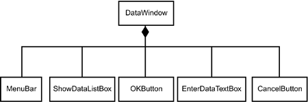
A typical UML model would present a particular application's window as a composite of a number of controls, as in Figure 24.2.
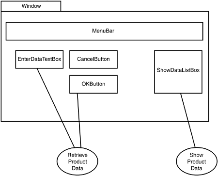
You can use attributes to add the spatial location of each component—a horizontal location and a vertical location, both measured in pixels. Another pair of attributes could represent the component's size (height and width). It's easier to comprehend those parameters, however, if you visualize them. You can specify that a package will represent a window and that the location and size of objects within the package reflects their location and size in the window. Figure 24.3 shows this.
Figure 24.4 is the hybrid diagram that adds the finishing touch by showing the connections with use cases.
This type of modeling doesn't preclude showing screen shots. Instead, it can be a helpful addition—a schematic diagram that keeps the big picture in view.
Expert systems experienced a surge in popularity in the 1980s. Something of a curiosity when they first appeared, today they're part of the mainstream of computing.
An expert system is designed to capture the insights and expertise of a human expert in a specific domain. It stores that expertise in a computer program. The intent is to use the expert system to answer repetitive questions so the human expert doesn't have to or to store the expertise so that it's available when the expert is not.
The expertise resides in the expert system's knowledge base as a set of if-then rules. The if-part of each rule describes some real-world situation in the expert's domain. The then-part of each rule indicates the course of action to take in that situation. How does the expertise get into the knowledge base? A knowledge engineer holds extensive interviews with an expert, records the results, and represents the results in software. It's similar to the interview that takes place in a domain analysis, although knowledge-engineering sessions are typically more extensive.
The knowledge base isn't the only component in an expert system. If it were, an expert system would merely be a laundry list of if-then rules. What's needed is a mechanism for working through the knowledge base to solve a problem. That mechanism is called an inference engine. Another necessary piece of the puzzle is a work area that stores the conditions of a problem the system has to solve, creates a record of the problem, and displays the solution. One more component, of course, is the user interface for entering the problem conditions. Condition entry may proceed via checklist, question-and-multiple-choice-answer, or in extremely sophisticated systems via natural language. Figure 24.5 shows a class diagram of an expert system.
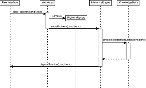
To interact with an expert system, a user enters the conditions of a problem into the user interface, which stores them in the work area. The inference engine uses those conditions to go through the knowledge base and find a solution. Figure 24.6 presents a sequence diagram for this process.
If you can form an analogy between an expert system and a human, you've pretty much got it: The work area is roughly analogous to a person's short-term memory, the knowledge base is like the long-term memory, and the inference engine is the problem-solving process. When you “rack your brain” to come up with an answer to a sticky problem, you're doing something like what an expert system does.
An inference engine usually goes through its knowledge base (“racks its brain”) in one of two ways, and the best way to explain is with an example. Suppose you have an expert system that captures the expertise of a plumber. If you had a leaky faucet, you'd use the expert system by entering the details of the leak into the system. The inference engine would do the rest.
Two of the rules in the knowledge base might look like this:
Rule 1: |
|---|
IF you have a leaky faucet |
AND the faucet is a compression faucet |
AND the leak is in the handle |
THEN tighten the packing nut |
Rule 2: |
IF the packing nut is tight |
AND the leak persists |
THEN replace the packing |
Without getting into the specifics of the plumbing world, suffice it to say that these two rules are obviously related—notice the similarity between the then-part of Rule 1 and the if-part of Rule 2. That similarity is the basis for working through the knowledge base, which typically has many, many more than two rules. The inference engine might start with a potential solution, like “replace the packing” from Rule 2, and work backward to see whether the specifics of the problem demand that solution.
How does the inference engine work backward? It looks at the if-part of the rule that has the solution and tries to find a rule whose then-part matches it. In the two-rule example, that's easy—Rule 1 has a matching then-part. In industrial-strength applications, it's not so easy because a knowledge base might store hundreds, even thousands, of rules.
After the inference engine has found a rule, it checks to see whether the conditions in the if-part match the conditions of the problem. If they do, the engine keeps moving in the same direction—a matching if-part, check the if-part, another matching if-part, and so forth. When the inference engine runs out of rules, it asks the user for more information. The point of all this is that if the path through the rules is successful (that is, matches the conditions of the problem), the expert system offers the original potential solution as the solution to the problem. If not, the system tries a new path.
This technique of trying a solution and seeing whether the associated conditions match the conditions of the problem is called backward chaining—“backward” because it starts with then-parts and proceeds to examine if-parts.
As you can imagine, another technique starts with if-parts and matches then-parts, and it's called forward chaining. Here's how it works: The user enters the conditions of the problem, and the inference engine finds a rule whose if-part matches the conditions. It checks that rule's then-part and looks for a rule whose if-part matches that then-part. In this example, suppose Rule 1's if-part matches the problem conditions. The inference engine checks Rule 1's then-part and then looks for a rule with a matching if-part. Again, this is easy with only two rules. When the system runs out of rules to match, it offers the then-part of the final rule as the solution. The forward in forward chaining refers to this movement from if-parts to then-parts.
If you were to model an expert system as in Figure 24.5, it would be helpful to add a stereotype that indicates the type of chaining the inference engine performs. You would add either «forward chaining» or «backward chaining» to the composite ExpertSystem class.
What can the UML add to all this, and why would we want it to? One of the sticking points in expert system development is the lack of a solid standard for a visual representation of the knowledge base rules. A UML-based representation would go a long way toward standardizing the field and toward encouraging good documentation practices. It's not enough for the knowledge to reside in a software representation in a knowledge base—the rules should all be in a document as well.
Another sticking point is that use case analyses are rarely done in the course of developing an expert system. A use case analysis, complete with UML use case diagrams, might help determine the best type of inference engine to use in an expert system implementation. The deployment diagram is still another possible point of UML applicability to expert system development. Although they were once stand-alone devices, expert systems today typically have to fit into a corporate computing structure and interact smoothly with other systems. Deployment diagrams can be used to show where an expert system resides and how it depends on (and feeds into) other areas of information technology. Given that an actor in a use case diagram can be another system, the deployment diagram and the use case diagram can work together to provide views of an expert system in a corporate context.
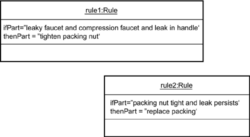
Let's focus on the knowledge base. How can you represent a knowledge base in the spirit of the UML? One possibility, of course, is to represent each rule as an object. Have one of the attributes be the if-part, another be the then-part, and add attributes as necessary. Figure 24.7 shows this arrangement.
Although this is eminently doable (and many developers do it), I believe rules are important enough to warrant their own representation—and not only because they serve as the foundation of knowledge bases in expert systems. The growing emphasis on knowledge management within organizations and institutions calls out for a unique way to represent rules.
What would that unique representation look like? First, you'd want to make sure you show something that gives the contents of a rule's if-part and the contents of its then-part. In order to make this representation useful, you'd also want to somehow visualize the connections among rules.
This can all get very thorny very quickly. Industrial-strength rules tend to have a lot more information than the two plumbing rules I showed you, and the rules tend to proliferate. You have to balance these proliferations against the need for simplicity.
Let's first create a simple icon to represent a rule. Begin with a box divided by a centered vertical line. The left half of the box represents the if-part and the right half the then-part. Within each part, you'll write a meaningful summary of the contents. Figure 24.8 shows what I mean, using the two plumbing rules as an example.
Now you have to incorporate some identification information for each rule. Across the top of each box, add a compartment that holds a numerical identifier. This accomplishes two things: (1) It makes each rule unique and (2) It shows where to go in a rules catalog for a complete description and explanation of the rule. If a rule is part of a subgroup of rules (as in a “faucet” subset of the plumbing knowledge base), you can treat the subgroup as a package. You then add the package information to the identifier in the UML's usual way—have the package name precede a pair of colons that precede the identifier. Figure 24.9 shows this addition.
Represent the relation between the two as a line between the then-part of Rule 1 and the if-part of Rule 2. Figure 24.10 shows the connection.
Unlike the two-rule set in this example, a rule in a real expert system is usually related to more than one other rule. If the related rules aren't nearby—either in the knowledge base or in the documentation—it will be helpful to have a way of showing the relationship even when you can't draw connecting lines.
Compartments at the bottom of the icon will do the trick. If you put them below the compartments you already have, you can show identifiers for other rules, as in Figure 24.11. The lower compartment on the left identifies rules whose then-parts connect to this rule's if-part. The lower compartment on the right identifies rules whose if-parts connect to this rule's then-part.
As is the case with class diagrams, compartments within the rule icon could be elided depending on the purpose of the diagram. The idea is to concisely show the connections among rules as well as their content and thus clearly communicate the nature of the knowledge base.
The model for the expert system is more drastic than the model for the GUI in that it proposes a new view element (the rule icon) for the UML. The model for the GUI, on the other hand, is a hybrid diagram that consists of current UML elements.
Since the first edition of this book appeared, a number of analysts have created sets of UML extensions for important domains. In this section, we examine one for Web application development.
Simply put, a Web-based system allows an end-user with a browser (a software application on a client computer) to access and view a document that resides on a host computer (a server). A Web application augments a Web-based system by adding business functionality, like the ability to add selections to a shopping cart and to complete transactions via credit card.
The Web Application Extension (WAE) to the UML is the brainchild of Rational's Jim Conallen. This profile includes about a dozen graphic stereotype icons, additional stereotyped associations, attributes, and some “well-formedness” rules for combining all these elements to create a model.
Each element is associated with zero or more tagged values. Recall from Hour 14 that a tagged value is a bracketed string consisting of a tag, an equal sign (=), and a value. Its purpose is to provide important information about an element. In the WAE, for example, the tagged value for a Web page shows the path that specifies the Web page on the Web server.
While you're on the subject, Figure 24.12 shows the WAE icon for a Web page.
Notice the similarity between this icon and the UML icon for a note. The folded corner is designed to reinforce the notion of a page. Keep in mind that conceptually a Web page is a class with attributes and operations, and a specific Web page is an object. (See Exercise 1.)
Figure 24.13 shows WAE icons for three types of pages that can appear in a Web application: a server page, a JavaServer Pages (JSP) page, and an Active Server Page. Figure 24.14 shows three more: client page, frameset, and servlet.
The WAE has icons for structures other than pages. For example, when you surf the Web you often see pages whose components allow you to enter information into the page (check boxes, radio buttons, combo boxes, and more). A collection of these components for a particular page is called a form, and Figure 24.15 shows the WAE icon for a form.
The WAE is much richer than the description in this section. For further details and updates, see Jim Conallen's Building Web Applications with UML Second Edition (Addison-Wesley, 2003). To download WAE icons and use them in a UML modeling tool like Rational Rose or Visio, visit www.wae-uml.org.
We've come to the end of the road. Now that you have a bag full of UML tricks, you're ready to go out on your own and apply them to your domain. You'll find that as you gain experience, you'll add to that bag of tricks. You might even come up with some suggestions for adding to the UML. If you do, you'll be carrying on a grand tradition.
Just after the beginning of the twentieth century, the renowned mathematician Alfred North Whitehead pointed out the importance of symbols and their use. A symbol, he said, stands for the presentation of an idea: The importance of a symbol is that it quickly and concisely shows how an idea fits together with a complex set of other ideas.
In the first decade of the twenty-first century, Whitehead's observations still ring true for the world of system development. Carefully crafted symbols show us the thought processes and complexities behind the wonderful systems we propose to build, and help us ensure their efficient performance when we build them.
As modelers extend and mold the UML to fit their needs, they'll shape its future. In this hour, you looked at an extension for business modeling and saw some ways of applying the UML to other areas. We also examined the Web Application Extension (WAE), which is a UML extension for modeling Web applications.
Taking a lesson from the business extension's simplicity, we explored ways for modeling GUIs and expert systems. To model a GUI, we set up a hybrid diagram that shows the spatial relationships of screen components and their connections with use cases. This has the advantages of showing the evolution of a GUI as it takes shape and keeping the appropriate use cases within the focus of attention.
In an expert system the if-then rule is the building block of the knowledge base, the component that contains the knowledge of a human domain expert. We suggested a diagram that visualizes the rules and their interrelationships. In this diagram, a box divided into compartments models the rule. One compartment contains the rule identifier, another summarizes the if-part, another the then-part, and two others show related rules. Links to nearby rules appear as connecting lines between appropriate parts of the rules.
The WAE encompasses a set of stereotyped icons, stereotyped associations, attributes, and rules for modeling a Web application. Many of the icons are designed to reinforce the idea of a page.
The questions in this workshop test your knowledge about applying the UML to GUIs and expert systems. The answers to the quiz questions are in Appendix A, “Quiz Answers.”
1: | Visit the home page of Sams Publishing (www.samspublishing.com) and use the WAE Web page icon to model that page. Next, model the page without using the WAE icon—that is, with a standard UML icon. |
2: | Imagine that an appliance manufacturer wants to create a Web-based expert system that provides troubleshooting information. When something goes wrong, an appliance owner would be able to go to this Web site, enter the symptoms, and receive advice on how to proceed. Perform a use case analysis, and use the information on expert systems and the WAE from this hour to create a rudimentary model of the Web site. |
