
2
Performance Tradeoffs and the Development of Standards1
2.1 Scope of Sense and Avoid
The purpose of a sense and avoid (S&A) function is to act in the place of a human pilot to detect and resolve certain hazards to safe flight. These hazards consist of other traffic or objects presenting a risk of collision. Air traffic encompasses aircraft, gliders, balloons and even other unmanned aircraft system (UAS). Other hazards include terrain and obstacles (e.g., buildings, towers, power lines).
As there is no human pilot aboard a UAS, the motivation of S&A is not necessarily to preserve the aircraft but it is certainly needed to prevent collisions with other traffic, with persons on the ground, or collateral damage to property. S&A must operate for emergency and diversionary events as well as throughout normal operations.
On a manned aircraft, the human pilot is required to see and avoid hazards. The pilot's duties include regular visual scans across the forward field of view in order to detect other aircraft. The scanning may be more focused toward areas where operations are expected, or as informed by hearing radio traffic or by an electronic display. Whenever traffic is seen, the pilot must make a judgment about its trajectory relative to own aircraft motion, and determine whether any risk of collision might necessitate a maneuver. The ‘see and avoid’ process can be difficult in some conditions of poor visibility, confusing backgrounds or high workload. The premise that UAS S&A need only be as good as human see and avoid is looked upon unfavorably by airspace regulators.
Some UAS are too small to feasibly carry S&A equipment onboard. One solution for these aircraft is to operate them only within direct radio communication of the pilot and to maintain a visual line of sight between pilot and aircraft. This form of operation may prove sufficiently safe. Further restrictions may be imposed to limit risk, such as precluding operation over densely populated areas and limiting the mass of the aircraft that need not be capable of S&A.
This chapter discusses many considerations concerning the design of S&A, and presents important tradeoffs that need to be made. In contrast to the specific designs chosen by each implementation for their own purposes, the chapter also addresses the method of developing standards that present requirements that all implementations must meet, regardless of their design specifics.
2.2 System Configurations
There are numerous variations of S&A configurations. The main components are the aircraft and systems onboard; the off-board control station; and communication link(s) between these. The key distinctions involve two factors:
1. Whether the S&A surveillance system consists of sensors located onboard the aircraft, off-board, or distributed among both of these, and
2. Whether the S&A decisions are made at the off-board control station or onboard the aircraft by its automation.
Several example configurations are illustrated in Figures 2.1–2.3.
Figure 2.1 Sensor and decisions on the ground
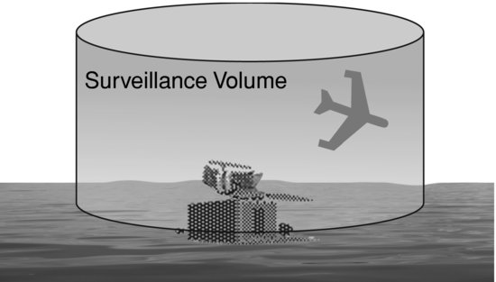
Figure 2.2 Sensors and decisions located aboard the aircraft
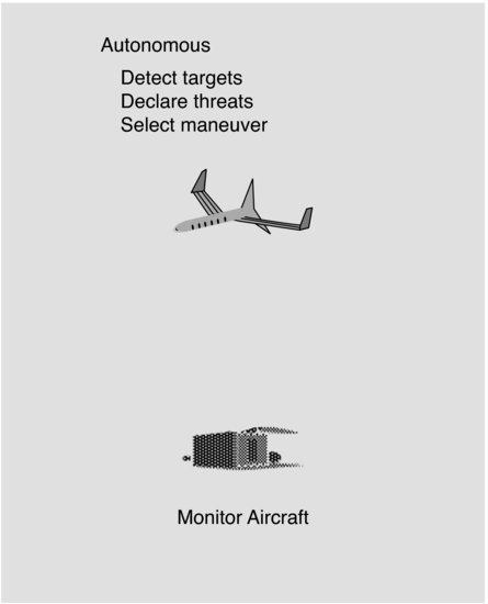
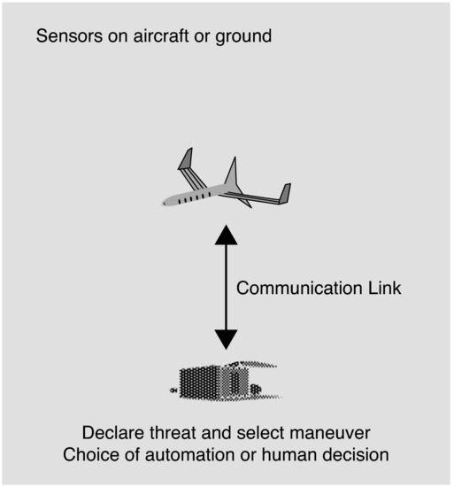
Figure 2.3 Sensors aboard the aircraft, decisions made on the ground
2.3 S&A Services and Sub-functions
The S&A function needs to supply two services. They are described here in accordance with agreements reached at the ‘Sense and Avoid Workshops’ where US FAA and Defense Agency experts discussed a number of fundamental issues [1]. These services are:
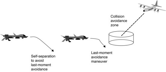
a. A ‘self-separation’ service that would act before a collision avoidance maneuver is needed, and could support earlier, gentler maneuvers. This is comparable to the visual separation maneuvers that uncontrolled aircraft could make in order to carry out the regulatory requirement to remain ‘well clear of other traffic’ [2]. Further definition is needed in order to reconcile the ability to perform this maneuver with the responsibility of air traffic control (ATC) to separate traffic (when the UAS is under ATC control). One option would be to use it under specifically delegated authority from ATC.
b. The collision avoidance service that attempts to protect a small ‘collision zone’ and usually is achieved by means of a late, aggressive maneuver. An example of this service is the resolution advice issued by the Traffic Alert and Collision Avoidance System II (TCAS II in the United States [4], or ACAS II elsewhere [5]) used aboard manned aircraft.
These services are illustrated in Figure 2.4.
Figure 2.4 Self-separation versus collision avoidance maneuvering
To achieve these services, the following list of sub-functions is required [1]:
1. Detect any of various types of hazard, such as traffic, terrain or weather. At this step, it is merely an indication that something is there.
2. Track the motion of the detected object. This requires gaining sufficient confidence that the detection is valid, and making a determination of its position and trajectory.
3. Evaluate each tracked object, first to decide if its track may be predicted with sufficient confidence and second to test the track against criteria that would indicate that a S&A maneuver is needed. The confidence test would consider the uncertainty of the position and trajectory. The uncertainty could be greatest when a track is started, and again whenever a new maneuver is first detected. A series of measurements may be required to narrow the uncertainty about the new or changed trajectory. Also, when a turn is perceived, there is uncertainty about how great a heading change will result.
4. Prioritize the tracked objects based on their track parameters and the tests performed during the evaluation step. In some implementations, this may help to deal with limited S&A system capacity, while in others prioritization might be combined with the evaluation or declaration steps. Prioritization can consider criteria for the declaration decision that may vary with type of hazard or the context of the encounter (e.g., within a controlled traffic pattern).
5. Declare that the paths of own aircraft and the tracked object and the available avoidance time have reached a decision point that does indeed require maneuvering to begin. Separate declarations would be needed for self-separation and collision avoidance maneuvers.
6. Determine the specific maneuver, based on the particular geometry of the encounter, the maneuver capabilities and preferences for own aircraft, and all relevant constraints (e.g., airspace rules or the other aircraft's maneuver).
7. Command own aircraft to perform the chosen maneuver. Depending upon the implementation of the S&A, this might require communicating the commanded maneuver to the aircraft, or if the maneuver determination was performed onboard, merely internal communication among the aircraft's sub-systems.
8. Execute the commanded maneuver.
If any aspects of the Evaluate or Determine sub-functions are to be performed at the control station, air–ground communication becomes critical. It is a matter of design as to whether all tracked targets are sent to the ground for evaluation, or if the aircraft sub-system performs some further sub-functions beyond Detect (e.g., Evaluate, Prioritize) in order to reduce the amount of air–ground communications. The latency and bandwidth of the data link are important considerations, as well as the feasibility of placing substantial processing capability aboard the UAS.
2.4 Sensor Capabilities
The surveillance system that detects hazards can be implemented in various forms. Some technologies could be carried onboard the UAS, while another approach is to exploit sensing on the ground, such as a radar. These choices have extremely different capabilities, ranging from their coverage volume to the types of measurements made and the respective accuracies, update rates and probabilities of false detection.
2.4.1 Airborne Sensing
Technologies available for airborne sensing of other aircraft are best divided into two groups, termed cooperative and non-cooperative.
Cooperative technologies are those that receive radio signals from another aircraft's onboard equipment. The leading cooperative technologies are:
a. ATC transponder. A large number of aircraft carry a transponder, which has long been used to respond to ground-based secondary radar interrogations for air traffic control usage. The same technology has been exploited for the manned aircraft Traffic Alert and Collision Avoidance System (TCAS).2 Aircraft are required to be equipped with transponders to operate in some classes of airspace (ICAO classes A, B and C; with altitude encoding in A and B).
b. Automatic Dependent Surveillance – Broadcast (ADS-B). This technology utilizes the Global Positioning System (GPS) or an alternate navigation source, and broadcasts own aircraft position, velocity and other data without needing to be interrogated. Standards for ADS-B are in place, and although its equipage is limited as of this writing, its widespread use is contemplated in NextGen and SESAR in the USA and Europe respectively, as well as certain other international locations. In the USA, those aircraft currently required to carry a transponder must equip with ADS-B for broadcast by 2020 [3].
Table 2.1 Typical sensor coordinate systems
| Sensor Technology | Coordinate System |
| Active interrogation of Mode A/C transponder | Relative range, absolute altitude |
| ADS-B | Latitude, longitude, altitude, velocity |
| Electro-optic | Bearing (azimuth and elevation) |
| Laser/LIDAR | Relative range |
| Onboard radar | Relative range, bearing (azimuth and elevation) |
| Ground-based radar | Range and bearing from ground reference |
| Acoustic | Bearing |
Since the detection of a cooperative signal should be reliable within its intended range, these technologies should be superior for target detection and track association. However, these can only detect suitably equipped aircraft that choose to ‘cooperate’ with ATC or other aircraft by equipping and operating that equipment. Some, but not all, classes of airspace mandate carriage of this equipment. In airspace where non-cooperative traffic is allowed, other technologies would be needed to detect traffic. Candidate technologies include electro-optic or infrared cameras, primary radar, laser range finding and acoustic processing. Each of these non-cooperative technologies has different limitations, particularly when miniaturized for mounting onboard an aircraft. No single approach appears to provide all the necessary measurement coordinates (angles and range to target) with good accuracy; optical and acoustic measurements are best for angular measurement, while radar and lasers are best for ranging (see Table 2.1). Equipping a UAS with a combination of S&A technologies might serve to combine the strengths of each. The combination could include both cooperative and non-cooperative elements. Measurements from the separate sensors would need to be associated. A design might utilize the existing knowledge base of data fusion techniques, and may use Kalman filtering to account for differences in accuracies between the sources. Further complication would arise if sensors differed in their update rates, as they would measure targets at different times, and thus in different locations.
2.4.2 Ground-Based Sensing
For smaller UAS, the size, weight and power required to equip with multiple sensors may be prohibitive. Ground-based sensing may be attractive for these UAS, although these sensors also have limitations, such as their accuracy and update rate. These limitations may be reflected in aircraft operations, using more conservative separation measures. These sensors’ field of view could also preclude long-range, low-altitude coverage. At present, radar is used for S&A in a small number of locations. The cost of a radar is likely suitable only for governmental use; private UAS operators would need to arrange access to the surveillance data.
Since the sensor technologies vary in their range and surveillance coverage, a system trade is needed to determine these requirements to meet required safety levels, considering also the timeline for declaration and avoidance maneuvering (Section 2.7) and evaluating the likelihood that a target initially outside the sensor's range or field of view would not be detected in time to avoid it. An operational trade may limit flights to some lesser volume contained within the surveillance volume, ensuring that entering targets can be acquired with high probability and sufficient warning time.
2.4.3 Sensor Parameters
Sensor technologies can be evaluated using standard parameters which can provide a basis for comparison, as well as characterizing the performance of the entire surveillance system.
- Field of view. This describes the angular sector within which the sensor makes measurements. When a target is outside the field of view, this sensor cannot detect or update it.
- Range. A distance measured from the sensor, within which some good probability of detection of targets may be expected.
- Update rate. This is the interval at which the sensor provides its measurements. If it does not detect the target at every interval, its effective update rate will be lower.
- Accuracy. This parameter describes the uncertainty of the sensor position measurement. It often addresses a single dimension, so that evaluation of the surveillance system must combine accuracy values for different dimensions to create a volume of uncertainty.
- Integrity. This represents the probability that a measurement falls beyond some limit characterizing its normal operation.
For cooperative sensors and targets, an additional parameter is relevant:
- Data elements. Specific data provided by the cooperative target to enhance the measurement or knowledge of surveillance. Examples include position, trajectory, identity, intent.
2.5 Tracking and Trajectory Prediction
The surveillance system needs to associate successive measurements with specific targets. Over time, a track is formed and updated for each target that is believed to be real. Various technologies are susceptible to varying degrees of noise, resulting in false detections. Another effect of measurement noise is stochastic variation of the position measurement, potentially making it difficult to associate one measurement of the target with the next. Both of these effects may require a design associating several consistent measurements before a valid track can be declared. The track then would be updated each time another consistent measurement is received. A measurement would be associated with an established track if its position agreed with the expected position (equal to the previous position plus estimated velocity times the update interval) within some predetermined margin of error. This margin must account for measurement and estimation uncertainties, as well as feasible maneuvers by the target. The update interval would depend on the technology, and typically would lie within 1 to 5 seconds.
The tracking function should be capable of maintaining the track for a certain time even in the absence of an update, as the detection function is likely to be designed for a good trade between valid and false detection; thus some updates would be missed. In this case, the track can be projected ahead to an expected position, but its uncertainty would grow. After too many updates are missed, the track would need to be dropped. In particular, any maneuver that began after the last detection would be unseen (Figure 2.5).
Figure 2.5 Surveillance system requirements
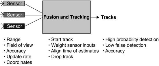
If the surveillance system is combining measurements from different technologies, their respective data should be aligned in time, properly compensated for uncertainties that differ by technology or dimension, and given appropriate weight. The function should strive to avoid creating duplicate tracks for the same target, but if this occurs, the receipt of additional data should enable the separate tracks to be associated and merged. Cooperative technologies should be more successful at uniquely identifying targets, as Mode S and ADS-B equipment provide a unique aircraft address within their reply formats.
The track should develop a velocity vector as the basis for predicting the trajectory of each target (except fixed objects or terrain). Additional data such as turn rate may enhance the projection. Features that attempt to detect the start or end of maneuvers are useful, especially in modulating the amount of uncertainty associated with the prediction. Even a track with large uncertainty can be of some use. The subsequent resolution decision may need to avoid a large volume to account for this uncertainty.
2.6 Threat Declaration and Resolution Decisions
Aircraft operations are conducted to perform some mission that could be disrupted by making unplanned maneuvers. Therefore it is important that S&A distinguish threatening from non-threatening traffic or other hazards, and call for a maneuver only when required for safety. The threat declaration function then must balance two primary requirements: to determine that a hazard poses a threat such that some maneuver is required, and to minimize these declarations for targets that are actually non-threatening. The timeline discussed below places further requirements upon the timing of the declaration.
A measurement of the range between UAS and a hazard is the basis for predicting the time to collision. For a true, linear collision trajectory, the time to collision is given by τ in:
![]()
Note that ![]() is negative when the UAS and the hazard converge. When the trajectory is not leading to a collision (i.e., a ‘miss distance’ would result), the task of threat determination is to decide whether some protected volume of airspace would be penetrated. Since other aircraft may make unforeseen maneuvers in the future, some additional margin may be provided to protect against adverse maneuvers (discussed further below).
is negative when the UAS and the hazard converge. When the trajectory is not leading to a collision (i.e., a ‘miss distance’ would result), the task of threat determination is to decide whether some protected volume of airspace would be penetrated. Since other aircraft may make unforeseen maneuvers in the future, some additional margin may be provided to protect against adverse maneuvers (discussed further below).
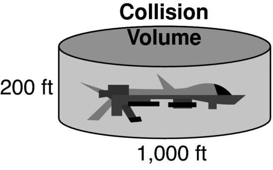
2.6.1 Collision Avoidance
The need for resolution must begin with a defined volume to be avoided. The usual choice for the collision avoidance function would equate to the ‘critical near-midair collision’ definition [4] of a truncated cylinder ±100 ft in height and 500 ft in radius (see Figure 2.6). This fixed volume is a surrogate for the actual dimensions of a threatening aircraft, as those dimensions are difficult to measure in the dynamic conditions of flight. The choice of resolution maneuver also must consider the latencies involved in deciding, communicating and executing the maneuver, the capabilities of the airframe in accelerating laterally, vertically or changing speed, the ultimate climb or descent rates or bank angle to be achieved, and other constraints deriving from airspace rules and other detected proximate traffic or hazards such as terrain.
Figure 2.6 Collision avoidance zone
The resolution choice also needs to consider compatibility with avoidance maneuvers to be made by the other aircraft in the encounter. Threat aircraft maneuvering visually would be expected to follow the customary right-of-way rules [2], while those threats making use of their own collision avoidance system would use its prescribed set of rules. TCAS, for example, uses vertical maneuvers. As of this writing, TCAS is the only system aboard manned aircraft that generates resolution advisories, but future airspace could see a variety of systems implemented, perhaps starting with systems placed onboard various UAS. These onboard technologies might migrate to some segments of manned aircraft that do not yet have collision avoidance capability (e.g., general aviation), if the operational and cost attributes become attractive. Therefore, since no single behavior can be expected from other aircraft, it will remain essential to coordinate maneuver choices between two equipped aircraft in an encounter, much as TCAS does at present. The TCAS process sends addressed messages from each aircraft to the other to explicitly exchange intent data. This process uses a priority protocol to resolve ties (e.g., when each aircraft has selected ‘climb’). Alternate means have been proposed to avoid transmitting these messages:
- Implicit coordination by observing the other aircraft maneuver. This would need to overcome difficulties in detecting the start of a maneuver, and still would need some mutual protocol to break ties or overcome differences of observation.
- Implicit coordination by design. This method might attempt to pre-select maneuvers based upon closing angle or closest approach point; or may restrict maneuvers to the lateral dimension against TCAS aircraft that presumably would only make vertical maneuvers. Difficulties would involve differences between each aircraft's observation of one another, as well as limitations from using pre-selected choices.
Using a different method of coordination also would introduce difficulties in remaining interoperable with existing TCAS-equipped aircraft. The first difficulty is proving that compatible advisories will be selected with extremely high reliability. Second is the limitation in current TCAS design where coordination uses the Mode S data link and only is performed against another TCAS-equipped aircraft.
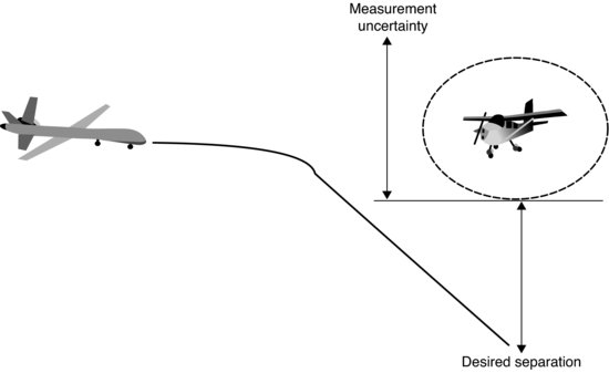
The magnitude of the avoidance maneuver must be sufficient to overcome errors. One such error is the position measurement. Another is the uncertainty in predicting a target's trajectory. A margin accounting for each of these would effectively expand the volume to be avoided (Figure 2.7) so that the maneuver would seek the sum of the desired separation plus the error margin. The ADS-B technology assists this provision, as the data provided by an aircraft is accompanied by an indication of the accuracy and integrity associated with it. For any other technology, the implementation needs to be coordinated with the algorithm design so that the error margin used for a target corresponds with the characteristics of the sensor measuring that target.
Figure 2.7 Accounting for uncertainty in determining maneuver
A long-standing challenge for collision avoidance algorithms is the ability to deal with maneuvers made by the threat aircraft. These can range from maneuvers begun shortly before a collision avoidance decision to maneuvers in the future that cannot be foreseen. Any algorithm must be tested against a credible range of maneuver possibilities and found to be robust, within the physical limits of aircraft maneuverability. Desired features include the ability to monitor the encounter as its resolution evolves and reconsider the original maneuver decision. Changed maneuvers may include stronger or weaker maneuvers in the same direction, a reversal within the same (horizontal or vertical) plane, a change to maneuver in the other plane, or resolution combining both horizontal and vertical avoidance. For some aircraft, speed changes also could be feasible for resolution. Depending on the aircraft maneuverability and the encounter specifics, some of these choices may not be available.
2.6.2 Self-separation
The self-separation maneuver described in Section 2.3 must evaluate targets and begin maneuvers earlier than collision avoidance, as its purpose is to avoid the more dangerous state requiring prompt and vigorous action. Its threat declaration function must anticipate future collision avoidance initiation, and determine when a maneuver is required to remain outside that state. In most respects, the principles of self-separation parallel those for collision avoidance. Coordination of maneuvers may not be required.
A potential constraint on the use of self-separation involves conditions that may be placed on the assignment of authority to make the maneuver. These likely will vary according to the UAS flight regime (under ATC control or not), and whether specific delegation authority to maneuver is received.
A system tradeoff between S&A surveillance capability and the self-separation maneuver involves the sensor system accuracy described above, whether the S&A surveillance range is sufficient to initiate track on the worst-case threat geometry, the magnitude of the self-separation maneuver itself, and both the communications latency and human latency (when decisions are not made entirely onboard the UAS).
2.6.3 Human Decision versus Algorithm
For the functions described in this section, it is a matter of design whether a human decision is involved or the process is partially or completely automated. A totally non-automated decision would show traffic or other hazard information to a human decision-maker, who would consider the UAS position and trajectory and would decide whether and when to make a threat declaration. The human also would select an avoidance maneuver. The arguments in favor of human decision could be:
- A human can have a current view of the ‘big picture’ including mission or airspace constraints, other surrounding traffic and own aircraft capabilities.
- Some may believe that alerting criteria and/or resolution priority rules are so situation-dependent that they cannot be captured in an algorithm.
- Concern that UAS pilot may not understand why an algorithm took a specific action.
Beyond merely providing traffic symbols on a graphic display, there is a range of further automation assistance that could be provided to a human decision-maker (normally the UAS pilot). These range from distance- or time-measuring tools on the display to projections showing whether a threat volume would be penetrated by the estimated trajectory, and finally to projections displaying hypothetical resolution outcomes. An intermediate step might use the automation to declare a threat, but then leave the resolution decision to the human. The arguments favoring reliance on algorithms and automation are as follows:
a. It is yet to be established that a remote pilot can effectively perform S&A using a traffic display for the full range of feasible encounter situations. Particularly for collision avoidance where time is short, the timeline may allow little margin for pondering whether action is necessary, and for interpreting graphical or numerical information to safely resolve the more difficult conflict geometries. One of the challenges for acceptance of a S&A system will be demonstrating the reliability of pilot decision-making. This will require sufficiently clear and complete information to be provided on the traffic display, optionally augmented by automation aids, and may also involve setting requirements for pilot qualification and training.
b. Another consideration is connected to the architecture decision. If a judgment is made that the communication link between aircraft and control station cannot be made sufficiently capable for the timely and reliable resolution of collisions, the aircraft may need to be equipped for automation of both detection and resolution functions.
Some people envision some similarities between the human roles in S&A and in air traffic control. With this line of thinking, crucial issues are overlooked. In fact, the human pilot role in the collision avoidance portion of S&A is only remotely like that of an air traffic controller. The latter role involves training with specific equipment to enforce authorized separation standards with relatively large distances compared to collision avoidance. The S&A collision avoidance task includes time-critical actions that directly control the flight of an aircraft. There is no relevant data on a controller's ability to perform collision avoidance, in part due to the limitations of the ATC traffic display accuracy and update rate, as well as the latency in communicating an instruction to an onboard pilot who then must execute it.
2.7 Sense and Avoid Timeline
Figure 2.8 depicts a notional timeline for S&A. The surveillance system needs to provide sufficient detection range so that a threat or hazard can be detected and the subsequent steps performed in time to resolve a collision. The surveillance range and the timeline of subsequent sub-functions need to act upon own and threat's relative trajectories with closing rates up to some designated maximum value. Several of the following steps potentially increase the time required to resolve a collision encounter:
- Sensor technologies that require multiple measurements to determine a valid detection.
Figure 2.8 S&A sub-function timeline
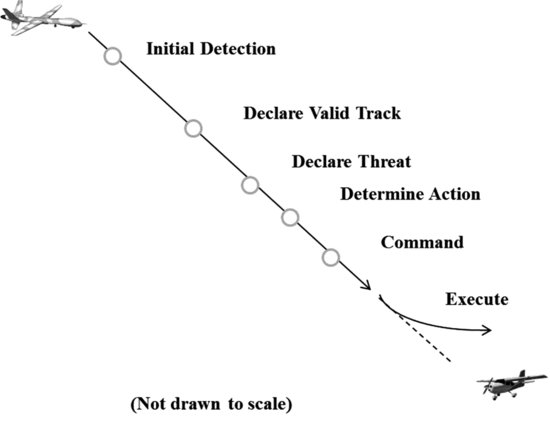
- Declaration of a threat, which could be delayed by factors such as measurement uncertainties, or the need to confirm that a candidate threat aircraft is maneuvering.
- Human decision time in determining the action to take.
- Communication delays in transmitting the action to the aircraft.
- Aerodynamic response of the aircraft in performing the intended maneuver.
In the author's opinion, the design of this timeline's components represents the greatest tradeoff challenge within S&A. The stochastic nature of several components, the complexity of a threat declaration algorithm, the potentially complex interaction of diverse sensor elements and the character of human delays make this a fascinating, complex problem.
The worst-case surveillance detection range then is the maximum combined closing speed multiplied by the sum of the processing times and delays. It might be argued that this worst case is unlikely, as all the maximum times should not occur in the same encounter. It then would be appropriate to calculate how likely lesser delays and lesser speeds would occur and design the timeline components accordingly, so long as the specified safety targets were met.
2.8 Safety Assessment
Approval to fly UAS in any airspace requires approval from the appropriate authorities. At present, approval is not straightforward, as regulations are very scarce regarding UAS. Authorities tend to evaluate airworthiness and operational approvals according to existing regulations for aircraft, but some shortfalls emerge as a result of the unmanned nature. Each of these approvals depends on a safety case, which must demonstrate that any foreseeable hazards would be controlled within an acceptable frequency. Some stakeholders tend toward proving ‘equivalence’ in some sense, compared to manned aviation. One difficulty with this approach is that manned aviation itself comprises disparate users and operations, so there is no single safety level to benchmark. A different approach follows the basic principles adopted for Safety Management Systems [6], which dictate that hazard frequencies be controlled in accordance with their consequences. The regulatory environment for UAS continues to evolve, pressed by growing user desire to access airspace with minimal restriction, but constrained by the regulatory responsibility to maintain safe airspace for all users.
The current thinking places S&A within the realm of operations rather than airworthiness. Operations within a region of airspace are regulated with some safety target as a basis. These targets may differ according to the operational use. For example, larger air carriers bear the burden of meeting a higher level of safety than do small private aircraft, due to their obligation to protect the traveling public. At the time of writing, safety targets for UAS have not been determined, and it is not clear that a single safety level would apply to all types of UAS or all operations.
Various methods of demonstration will be required to prove that a safety target is satisfied. Flight testing cannot suffice, as time and cost would preclude a large number of flights, and thus limit the amount of data collected. Instead, fast-time simulation should be used to prove the breadth of performance of S&A. This method has been used with great success for the development and standardization of TCAS [7]. Flight testing retains a role in validating the simulation results and ensuring effective integration of system components.
A critical step toward developing performance requirements will be performing safety assessment of S&A. This will involve the determination of operational hazards – an example would be a midair collision – that could arise from the failure or incorrect performance of each function or data flow constituting S&A.
Examples of failure events arising from the surveillance system could include:
- Aircraft not detected by surveillance sub-function.
- Aircraft detected late by surveillance sub-function.
- Aircraft detected with incorrect position or velocity.
The latter two of these involve complex analysis, since a ‘late’ or ‘incorrect’ detection may not cause a hazardous outcome with certainty, but would increase its likelihood. The relationship between the cause and the effect might depend on the design or technology involved.
The analysis should consider not only failures in resolving collisions, but also incorrect maneuvers that ‘induce’ a collision where none would have otherwise occurred. This is a very real hazard, which could arise from various causes, including measurement error, human decision, limitations in the algorithm, or even the communications link to the aircraft.
2.9 Modeling and Simulation
Several of the elements within S&A are stochastic in nature. Their interactions need to be fully explored so that adverse combinations of events are uncovered and considered in the proper context. The practical means of obtaining sufficient data involves modeling and simulation [8].
Monte Carlo simulation is an established technique that repeatedly simulates a situation with its components containing independently selected values from their respective models or probability distributions. For example, in a S&A simulation, an encounter geometry would be run repeatedly, each time using a different value of measurement error, pilot delay, communication link delay and other component values as appropriate. This would be repeated for a comprehensive set of encounter geometries and other factors (e.g., targets with or without cooperative equipage). The selection of encounter features and component values would correspond to their likelihood, and the results of the simulations might compare the distribution of separations achieved by the S&A process in repeated trials versus the separation if no avoidance action were taken. Models need to be obtained for each element in the architecture. Figure 2.9 shows an example using several onboard sensors, a communication link to a ground-based control station, and a pilot who either determines or evaluates a resolution and sends commands to the aircraft.
Figure 2.9 Example S&A implementation for simulation
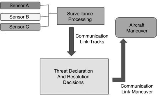
For this example, the onboard surveillance system consists of several sensor technologies whose measurements are to be combined within a track fusion function. This surveillance system needs to be modeled, with each sensor represented by its appropriate field of view and range, its measurement parameters such as accuracy, update rate and probability distribution of measurement error, and the track fusion process. This model would be able to simulate the attempted detection and tracking of threat aircraft whose positions change as they and the UAS follow their respective flight trajectories.
Another model is needed to simulate encounters. Statistics of encounters are needed so that a comprehensive set may be generated to represent encounters expected by the UAS in the intended airspace. The encounters must provide for horizontal and vertical profiles, both constant rate and maneuvering. The range of realistic speeds and approach angles need to be evaluated. It is not sufficient to record and replay observed encounters. First, there is very little UAS operation taking place in non-segregated airspace. Second, a data collection effort is unlikely to observe enough of the more challenging geometries (e.g., maneuvering) that must be simulated in large numbers in order to assure robust performance.
Whereas models for manned aircraft encounters have been created from observed flight data, UAS operations should primarily differ in many respects due to their aerodynamics as well as the types of mission flown. An agreed method of modeling the UAS flight locations and profiles would need to be combined with the profiles of other traffic, to create synthetic encounter statistics.
In this example, tracks of detected aircraft are sent to the ground for evaluation by the pilot. The threat detection and resolution decisions could be performed either onboard the aircraft or on the ground; this example assumes that the pilot would evaluate the traffic picture before approving a resolution choice and sending it to the aircraft for execution. The communication downlink of traffic and uplink of maneuver instructions both need to be modeled. Communication links exhibit latency, availability and error rates. Each of these may be stochastic and may vary according to conditions (e.g., air–ground range, or blockage by terrain or buildings).
If a candidate algorithm is under consideration, it should be used within the simulation, processing the simulated inputs in order to represent the event and timing of declaring a threat and selecting the maneuver. Pilot actions, whether involved in threat declaration and maneuver choice, or merely in approving an algorithm's choice, need to be modeled, as human decision time and performance (e.g., accuracy of maneuver response) will exhibit variation.
Finally, the aircraft maneuverability must be modeled so that the maneuver performance truly represents the UAS. The aerodynamic performance may vary according to factors such as altitude, weight, speed and any restrictions placed upon maneuvering.
2.10 Human Factors
The performance of a human pilot has many aspects across UAS operations. There are differences of opinion as to whether the pilot needs to be trained or even experienced in piloting manned aircraft, or whether the specific operations of the UAS constitute sufficient qualification. Regarding S&A, specific functions would dictate the skills required of the human and the data and formats of presentation supporting those functions.
The level of autonomy is one of many design tradeoffs. Regardless of the level chosen, the safety requirements must be satisfied. An example of the trades concerns the cost and reliability of implementing automation (with autonomy representing extreme automation) versus the complexity of evaluating and demonstrating successful human performance.
The self-separation function bears some resemblance to air traffic control separation tasks, though distances, rules and time lines differ. Voice communication to the UAS is not contemplated, at least at the present state of technology maturity. The collision avoidance function, though, is less like ATC operation.
The display of data would need to support awareness of the traffic and fixed hazard positions and dynamics, airspace constraints, terrain and obstacle locations if known. Air traffic controllers customarily see a plan view (horizontal plane) display of a fixed geographic area. Targets are displayed with data blocks associated with aircraft that provide their altitude, identity and airspeed. ATC separation instructions typically involve either a heading change that preserves a defined lateral separation distance, or a flight level change. The TCAS cockpit displays likewise use plan view, but unlike the ATC display show the (moving) host aircraft depicted at a fixed reference point and other traffic displayed so as to indicate their relative lateral position and motion. In the case of TCAS, its automation determines the vertical avoidance maneuver and no lateral maneuvering based on its display is authorized.
Unlike ATC, which uses standard separation minima, the UAS self-separation criteria would need to be adjusted according to appropriate margins calculated to account for measurement and prediction errors, plus sufficient margin to account for delays in delivering maneuver commands to the aircraft. These margins depend on the specific architecture and system design, and could vary dynamically depending on such factors as the sensors or communication links in use.
If the display is augmented with automation aids, these should be chosen so that they assist in reliable decision-making and ensure conspicuity when timely decisions are required. Likewise, the means of communicating maneuver instructions to the aircraft must be easily accessible and supportive of correct and accurate input. Some interest has been expressed in equipping a pilot to control multiple UAS. In this situation, it is essential to avoid confusion in associating pilot actions with the desired aircraft, as well as directing the pilot's attention to any situation requiring prompt evaluation.
It is possible to envision a wide variety of display and automation possibilities supporting S&A. A challenge will be to characterize the human use of each distinct implementation, to assure that specified performance targets are achieved, and then demonstrate that results obtained in a simulation environment will translate to equivalent safety for actual operations [9].
2.11 Standards Process
Standards are expected to play an important role supporting the certification of UAS to enable operations in civil airspace without the extreme restrictions imposed today. The S&A function is a notable area where the use of an approved standard can provide fundamental support to an applicant's safety case, since the function would replace one or more functions traditionally performed by the human pilot aboard manned aircraft. While some aspects of human performance are extremely difficult to quantify, the UAS version will need to be demonstrated to meet safety targets yet to be prescribed.
Standards typically provide direction to system developers toward achieving system certification and operational approvals. By demonstrating conformance to the standard's requirements, much of the work to prove the safety case would be accomplished. The standard must provide a comprehensive set of requirements that would assure safety and operational compatibility, as well as a prescribed suite of tests for demonstrating its requirements are met by a candidate implementation.
The standards process has traditionally begun with evidence of a mature technology. In the case of UAS, many aspects of aircraft and system design and operation have been demonstrated, but S&A remains in the research and experimental phases. The following series of steps describe the process planned for standards within the RTCA, Inc. Special Committee 203.
2.11.1 Description
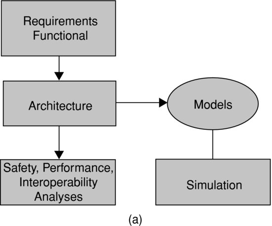
Since UAS standards will encompass many aspects of the system and operations, the process begins with an operational system and environment definition. This aims at describing the system functional elements and concepts of operation, the range of performance attributes for unmanned aircraft, and the airspace structure and its management system. These descriptions will support the subsequent analyses of safety, performance and interoperability.
2.11.2 Operational and Functional Requirements
The next step of the process is to enumerate operational and functional requirements. These describe ‘what’ needs to be done, although at this stage they do not state ‘how well’.
2.11.3 Architecture
System architecture defines functional elements and data flows that are envisioned to perform the main functions. There can be more than one variation. A good example involves pilot-in-the-loop versus autonomous S&A. The latter would not require communication links to and from the control station for the purpose of the S&A operations.
The architecture work within the standards process involves the development of a number of documentation artifacts, sometimes called ‘views’ of the UAS system. These range from operational concepts and use cases to system connection diagrams at the functional level, allowing enumeration of all sub-functions and data flow requirements from one sub-function to another. While this work involves a great amount of analysis and documentation, it ensures that all cases are thoroughly considered and that each analysis covers a documented definition of the system.
2.11.4 Safety, Performance, and Interoperability Assessments
The safety assessment analyzes the potential failures of each function and data flow from the architecture step. It identifies the consequence of the failure and the corresponding likelihood for acceptance of that risk. This step provides crucial information for the allocation of risks (to follow) and identifies areas where additional mitigation of risks can be considered. The measures for specifying event likelihoods need to relate to an overall safety target. In aviation today, safety targets differ between air carriers and certain other user types. It must be determined where UAS fall within this spectrum and if some UAS may be treated differently than others. It remains a matter of discussion as to whether this could depend on aircraft size and weight, airspace, mission type or other factors.
Some requirements do not have a direct bearing on safety, but are needed for other reasons such as ensuring compatible operations with other airspace users. A performance assessment determines the quantitative requirements for functions in this case. An example might be to measure the successful performance of the self-separation function. Its failure may have some safety impact, though less so than a collision avoidance failure; meanwhile, the same failure of self-separation may be required to be infrequent for operational reasons. Thus, the performance assessment also can influence quantitative requirements.
An interoperability assessment may take two forms for S&A. The first may address technical interoperability. A good example would be the specific equipment, signals and formats required to interoperate with cooperative aircraft or ATC, or to coordinate resolutions with other collision avoidance systems. The second form involves interoperability with ATM. Its scope is still to be determined, but might impose constraints to ensure compatibility with airspace structure or rules of the air.
The steps to this point are illustrated in Figure 2.10(a).
Figure 2.10 (a) Initial steps toward standards development
2.11.5 Performance Requirements
At the conclusion of these several assessments, performance requirements for functions and data flows will have been identified. It is possible that certain requirements may appear infeasible or at least undesirable for economic reasons. A process of allocation of requirements between functions would allow certain tradeoffs to be made so as to make certain requirements less onerous without compromising overall safety or operational performance. For example, achieving a long sensor range might be difficult, so maneuvering could be planned to begin later. Another example concerns data link performance. Instead of providing an extremely robust link, threat declaration might be adjusted to begin maneuvers earlier and operate safely despite a brief link outage.
2.11.6 Validation
A standard is expected to present validated requirements. The modeling and simulation work should be used to evaluate S&A metrics over the expected encounter space. Some flight testing should be performed to reinforce the simulation results.
Figure 2.10 (b) Completing standards development
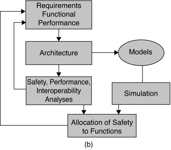
These important steps are shown in Figure 2.10(b). With these completed, the way is clear to write the standard.
2.12 Conclusion
The choices available to implement S&A are varied and involve complex trades between sub-system requirements. These will likely vary according to operational needs and the choices of technologies and architecture used in individual implementations.
The use of standards should simplify the regulatory approvals of S&A systems, inasmuch as their development includes the validation of performance requirements. This validation needs to include a thorough end-to-end simulation of system elements. The simulation in turn depends upon use of representative models.
References
1. Federal Aviation Administration, ‘Sense and Avoid (SAA) for Unmanned Aircraft Systems (UAS)’, October 2009.
2. US Code of Federal Regulations -- Title 14 Aeronautics and Space; Part 91 General operating and flight rules; Section 111, ‘Operating Near other Aircraft’ and Section 113, ‘Right-of-way rules: Except water operations’.
3. US Code of Federal Regulations -- Title 14 Aeronautics and Space; Part 91 General operating and flight rules; Section 225, ‘Automatic Dependent Surveillance – Broadcast (ADS-B) Out equipment and use’.
4. Minimum operational performance standards for traffic alert and collision avoidance system II (TCAS II) version 7.1, DO-185B, RTCA, Inc., June 2008.
5. Airborne Collision Avoidance System (ACAS) Manual, Doc 9863, 1st edn, International Civil Aviation Organization, 2006.
6. Federal Aviation Administration Safety Management System manual, Version 1.1, May 2004.
7. McLaughlin, M., Safety Study of the Traffic Alert and Collision Avoidance System (TCAS II) – Final Version, MTR97W32, The MITRE Corporation, June 1997.
8. Zeitlin, A.D., Lacher, A.R., Kuchar, J., and Drumm, A., Collision Avoidance for Unmanned Aircraft: Proving the Safety Case, MP060219, The MITRE Corporation, 42-1017, MIT Lincoln Laboratory, McLean, VA and Lexington, MA, October 2006.
9. Tadema, J., Unmanned Aircraft Systems HMI and Automation, Shaker Publishing, Maastricht, 2011.
1. This work was produced for the US Government under Contract DTFAWA-10-C-00080 and is subject to Federal Aviation Administration Acquisition Management System Clause 3.5-13, Rights In Data-General, Alt. III and Alt. IV (October 1996). The contents of this material reflect the views of the author and/or the Director of the Center for Advanced Aviation System Development. Neither the Federal Aviation Administration nor the Department of Transportation makes any warranty or guarantee, or promise, expressed or implied, concerning the content or accuracy of the views expressed herein. Approved for Public Release: 11-3338. Distribution Unlimited.
2. The system is known as Airborne Collision Avoidance System (ACAS) outside the United States.