
4
Regulations and Requirements
In civil aviation, several mechanisms are present to minimize the probability of collision with other aircraft, objects or terrain. Generally speaking, they are categorized as separation assurance and collision avoidance.
The first category aims to keep aircraft separated according to minimum separation distances both in the lateral and vertical planes. These minimum values depend on several factors, such as the airspace class, the flight rules, the flight phase, the air traffic control (ATC) surveillance means (if any), the performance of the onboard navigation systems, etc. Roughly speaking, lateral minimum separation between aircraft can range from 3 nautical miles in terminal areas with ATC radar separation service to up to 60 nautical miles for two aircraft at the same altitude in a North Atlantic track. Yet, in non-controlled airspaces minimum separation does not involve precise separation minima and aircraft must remain well clear from each other. Well clear is a qualitative rather than a quantitative term used in current regulations when referring to the minimum miss distance between two aircraft that are avoiding a collision.
On the other hand, collision avoidance is considered as a last resort manoeuvre to prevent a collision in case of a loss of separation. In some cases, collision avoidance between aircraft is performed cooperatively, meaning that two conflicting aircraft use common systems and procedures which have been designed to jointly detect an imminent collision with enough time to react and avoid it. However, not all aircraft are equipped with these systems and obviously neither are other flying obstacles, such as birds, or terrain. Thus, whenever visibility conditions permit, every pilot in manned aviation is expected to see and avoid these hazards. This means that in these conditions, flight crew is ultimately responsible for ensuring aircraft safety by preventing and avoiding collisions.
Unmanned aircraft systems (UAS) do not have the flight crew onboard and therefore, the see and avoid capability is essentially lost. Yet, UAS can be equipped with several sensors and mechanisms that can replace this unavoidable functionality. Thus, the more appropriate term sense and avoid (SAA) is used for UAS and in [1], it is simply defined as: ‘the process of determining the presence of potential collision threats, and manoeuvring clear of them; the automated equivalent to the phrase “see and avoid” for the pilot of a manned aircraft’. Briefly, the bare minimum features for an SAA system can be summarized as follows:
- detect and avoid mid-air collisions with other flying traffic according to the right-of-way rules;
- detect and avoid other flying objects (such as birds);
- detect and avoid ground vehicles (when manoeuvring on ground);
- detect and avoid terrain and other obstacles (such as buildings or power-lines);
- avoid hazardous weather; and
- perform functions such as maintaining separation, spacing and sequencing, as done visually in manned aviation.
Several issues arise when trying to apply current regulations (developed for manned aviation) to UAS, and SAA is obviously one of the most challenging. Significant operational differences exist between UAS and manned aircraft which have to be addressed before UAS can be safely integrated into civil and non-segregated airspace. In this context, an excellent review on existing manned and unmanned regulations world-wide, along with valuable thoughts and recommendations on this UAS integration, is given in [2].
UAS operations in civil airspace are asked to provide at least the same level of safety as that of manned aviation. This chapter focuses on regulations, requirements and open issues specific to SAA systems for UAS. First, some background information is given on separation and collision avoidance mechanisms, flight rules and airspace classes, UAS categorization and how safety levels could be defined prior to establishing minimum system requirements for SAA. Then, in Section 4.2, the existing regulations and standards on SAA are presented while Section 4.3 highlights the possible requirements that could be demanded of a SAA system. Finally, Section 4.4 is devoted to some discussion on human factors and situational awareness, while Section 4.5 concludes this chapter.
4.1 Background Information
Separation assurance and collision avoidance include several layers of protection against collisions that use different systems, procedures, airspace structure and human actions. Figure 4.1 depicts these different mechanisms, which are summarized as follows:
Figure 4.1 Separation and collision avoidance mechanisms
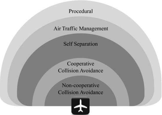
- Non-cooperative collision avoidance is the lowest-level mechanism to prevent an imminent collision with any type of aircraft, obstacles or terrain. In manned aviation, this relies entirely on the ability of the crew members to see and avoid. Conversely, for UAS this functionality must be assumed by an SAA system.
- Cooperative collision avoidance includes all the systems and procedures between cooperative aircraft that can avoid imminent collisions. The standard for an airborne collision avoidance system (ACAS) is specified by the International Civil Aviation Organisation (ICAO) in [3], defining it as an aircraft system based on secondary surveillance radar (SSR) transponder signals, which operates independently of ground-based equipment to provide advice to the pilot on potential conflicting aircraft that are equipped with SSR transponders. The traffic collision avoidance system (TCAS) is a particular ACAS implementation widely used in commercial aviation. ACAS/TCAS-I systems just provide traffic alerts (TA) when a collision threat is detected. In addition to TAs, ACAS/TCAS-II systems provide the pilot with resolution advisories (RA), proposing an avoidance manoeuvre in the vertical plane. Future TCAS versions also foresee horizontal manoeuvres in the resolution advisories.
- Self-separation mechanisms are the lowest layer that can guarantee a minimum safe separation distance. In manned aviation, see and avoid mechanisms are again widely used for this purpose, especially in non-controlled airspace under visual meteorological conditions. Besides this, self-separation can be significantly improved with different kinds of airborne separation assistance systems (ASAS), which consist of highly automated systems that present the pilot with information to enhance their situational awareness. Moreover, ASAS can even provide a set of explicit solutions to guarantee separation with other aircraft while reducing the workload of the crew. The majority of ASAS applications are based upon the automatic dependent surveillance (ADS) concept (where each aircraft transmits its position and likewise receives the positions transmitted by other aircraft or vehicles using the same system); and some sort of cockpit display traffic information (CDTI). Thus, these types of application are expected to dramatically enhance the situational awareness of the pilot and consequently, the safety levels in non-controlled airspace; although they are also aimed at delegating separation tasks from controllers to pilots in some controlled airspaces.
- Air traffic management (ATM) consists of a wide set of mechanisms and services aimed at providing the maximum capacity to airspace and airports in order to accommodate demand while ensuring the high levels of safety of civil aviation. ATM can be divided into three main categories: airspace management (ASM); air traffic flow management (ATFM); and air traffic services (ATS). The latter includes alert services (AS), flight information services (FIS) and finally air traffic control (ATC). The availability of these services depends mainly on the flight rules and class of airspace the aircraft is evolving.
- Operational procedures are the outermost layer in assuring separation with other aircraft (along with known obstacles and terrain). Here, we find not only navigation procedures but also aircraft operating procedures.
Among all the previous layers, the non-cooperative collision avoidance function is the most challenging one for UAS. The remaining layers are to some extent more likely to be easily integrated into a UAS with the currently available technology and regulations. Thus, SAA is one of the main issues that must be addressed before integrating them into civil and non-segregated airspace.
As already commented, the particular mechanisms available for each of the previous layers depend on several factors, such as the type of aircraft, airspace, meteorological conditions, flight rules, etc. For example, in non-controlled airspace the ATM layer is hardly present; in instrument meteorological conditions (IMC) the ability to see and avoid will be drastically reduced for manned aircraft; self-separation mechanisms will be undoubtedly different if ADS is available or not for all the aircraft, etc. Furthermore, other considerations specific to UAS operations exist: like the automation level of the UAS (autonomous, automated or remotely controlled); the type of communications relay with the control station; or even the presence of UAS operators in the airfield of operations. Moreover, flights over populated areas also raise increased safety issues as minimum safety figures are usually derived from the number of fatalities that an accident may cause [2].
4.1.1 Flight Rules
The ICAO specifies in its 2nd Annex to the Convention on International Civil Aviation [4] the rules of the air and the right-of-way rules. Each state is responsible for accepting and eventually adapting these rules for their national regulations. For example, in the United States, flight rules are defined in the Federal Aviation Regulations (FAR), Part 91. Two types of flight rule are established for manned aviation: visual flight rules (VFR) and instrument flight rules (IFR). VFR operations are based on visual cues that the pilot takes from outside the cockpit, not only for aviating the aircraft but also for navigating and avoiding collisions with other aircraft, obstacles and terrain. Yet, in certain classes of airspace, separation instructions may be provided by the ATC. Nevertheless, instructions will remain as simple headings, altitude changes or position reports asking to identify visual reference landmarks or relative visual positions inside the airfield traffic pattern. Visibility and cloud ceiling are the most important factors for safe VFR operations. These minimum weather conditions vary depending on the type of airspace in which the aircraft is operating and whether the flight is conducted during day or night time. Meteorological conditions that allow VFR flight are referred to as visual meteorological conditions (VMC) [4].
Conversely, IMC require pilots to fly solely by reference to flight instruments. Thus, pilots flying under IFR use several onboard instruments to aviate and navigate their aircraft and in almost all classes of airspace, the separation with other aircraft is ensured by an ATC service. ATC instructions may also be in the form of heading and/or altitude changes but, since IFR aircraft are always following navigation procedures, position reports may be based on radio-navigation aids and fixes. In some states, there exist a third category of flight rules; the special VFR (SVFR), which allows aircraft to fly in visual conditions with meteorological conditions below VMC minimums and up to a certain level of weather degradation. The actual values of SVFR minimum weather conditions vary on the type of airspace and state regulations and, in general, they are conducted only in controlled airspace and prior to an ATC clearance.
On the other hand, basic right-of-way rules state that the least manoeuvrable aircraft has always the right of way. For example, balloons have priority over gliders, which have priority over airships, which have priority over motorized heavier-than-air aircraft. In case of conflict between two aircraft of the same category, the aircraft on the right has the right of way. In case of a potential frontal collision, both aircraft must turn to their right and in case of an aircraft which is being overtaken, the last has the right of way and the overtaking aircraft must remain clear. Finally, aircraft in distress always have right of way over others.
4.1.2 Airspace Classes
Blocks of airspace are classified alphabetically into seven different categories (classes A, B, C, D, E, F and G) and are found in the ICAO in its 11th Annex to the Convention on International Civil Aviation [5]. This classification is defined in terms of flight rules (as seen above), interactions between the aircraft and the ATS and as a function of the airspace class, different operating rules apply.
In airspaces of class A to E, some level of ATC is provided and therefore these kinds of airspace are referred to as controlled airspaces. Classes A to E are ordered from most restrictive to least restrictive and consequently different levels of ATS are given, ranging from full separation assurance to all flights in classes A (where VFR flights are not allowed) and B; to separation only between IFR/IFR and IFR/SVFR flights in class E (where a clearance to enter is not even required for VFR flights). Conversely, airspaces F and G are non-controlled and only flight information services and eventual IFR/IFR separation are provided whenever possible in class F, while in class G there is no traffic information at all if not explicitly requested and possible. Table 4.1 summarizes these services for all types of airspace class.
Table 4.1 Summary of airspace classes and their basic characteristics
At national level, each state determines how the above-mentioned ICAO classifications are used and implemented in the design of their national airspace, according to their needs. Thus, not all ICAO classes are adopted by all the countries and some national aviation authorities even slightly modify their definition in order to fit former airspace rules and ATS that existed before the ICAO standardization came into effect. For example, in the USA class F airspace is not used (FAA Part 71), whereas it is defined in Canada; or in France neither classes B nor F are implemented. Furthermore, as a function of the state, other requirements may apply to different airspace classes such as the need to be equipped with appropriate communications, navigation equipment, transponder or collision-avoidance system; the minimum separation from clouds and visibility conditions for VFR flights; the maximum airspeed; or even minimum requirements on pilot certificates.
In Europe, Eurocontrol is proposing to simplify this classification and reduce the number of airspace classes to only three, which would roughly correspond to current classes C, E and G. According to [6], it is proposed to create three traffic environment ‘airspace categories’ as follows:
- Category N: airspace within which all of the traffic and all the intentions of the traffic are known to ATC.
- Category K: airspace within which all of the traffic is known, but not all of the intentions of the traffic are known to ATC.
- Category U: airspace where not all of the traffic is known to ATC.
4.1.3 Types of UAS and their Missions
There are several ways to categorize UAS based on different aspects of the system. For instance, UAS may be grouped as a function of the weight of the unmanned aircraft (UA); its performance; level of autonomy; altitude of operation; communications data link; or the type of operations or missions carried out. The most relevant examples of categorization of UAS are presented as follows.
Weight Categorizations
The UK Civil Aviation Authority divides the UAS according to vehicle weight [7]. The first category is called ‘Small Aircraft’, which includes aircraft weights lower than 20 kg. The next category is ‘Light UAV’ and comprises aircraft between 20 and 150 kg. The last category is just called ‘UAV’ and includes aircraft of 150 kg or more. Another typical categorization relates directly aircraft size (or weight) and type of expected mission. For instance, in [8] four different categories are given, the last one being split as a function of the operating altitude. Table 4.2 shows these types of UAS, along with some high-level parameters commonly found in each category.
Table 4.2 UAS classification as a function of UA weight [8]
Flight Performances
On the other hand, the Radio Technical Commission for Aeronautics (RTCA) proposes a categorization based on flight performance characteristics, remarking that ATC already uses flight performance for managing flows and maintaining separation. Thus, in their document Do-320 [9] the following categories are proposed:
- turbojet fixed-wing (e.g., Global Hawk, N-UCAS);
- turboprop fixed-wing (e.g., Pedator B);
- reciprocating/electric engine fixed-wing (e.g., Predator A, Shadow 200);
- VTOL (vertical take-off and landing) (e.g., Firescout, RMAX Type II);
- airship (e.g., SA 60 LAA).
However, within each of the five UAS categories, there is still a huge variability of UAS types and four additional sub-categories are also defined in [9] to further differentiate UAS:
- Standard category, representing those UA resembling manned aircraft.
- Non-standard small category, representing those UA with physical sizes and weight considerably smaller than the smallest manned aircraft.
- Non-standard high-altitude long-endurance (HALE) category, with altitudes and endurances that go beyond those of manned aircraft.
- Conversion category, which represents UAS that are converted from manned aircraft to operate as UA.
UAS Missions
Regarding the UAS missions, there is no doubt today that a huge market is emerging from the potential applications and services that will be offered by unmanned aircraft. UAS perform a wide variety of functions. Many UAS missions are described in the literature (see for instance [9--12]) and according to these references, civilian applications can be summarized in four groups: communications applications, environmental applications, emergency applications and monitoring applications. Within these categories, a wide range of application scenarios exist. For instance:
- Communications applications: telecommunication relay services, cell phone transmissions and broadband communications are just a few communications applications.
- Environmental applications: with the UAS capability for remote sensing, applications like atmospheric research, oceanographic observations and weather forecasting can be more effective.
- Emergency applications: this group includes fire fighting, search and rescue missions, oil slick observation, flood watch, hurricane watch and volcano monitoring.
- Monitoring applications: forest fire detection, international border patrol, fisheries monitoring or high-voltage power line monitoring are among the most important missions in this category.
Operational Behaviour
In [9], the RTCA describes another interesting categorization related to operational behaviours of UA once airborne. Three different flight profiles are presented, which represent generic operational UA behaviours. These are:
- Point-to-point UAS operations: direct flight and do not include aerial work or delays that may occur during the en route portion (transport of passengers or cargo).
- Planned aerial work: refer to orbiting, surveillance and tracking flights using predefined waypoints.
- Unplanned aerial work: UAS cannot predict their intended flight path.
4.1.4 Safety Levels
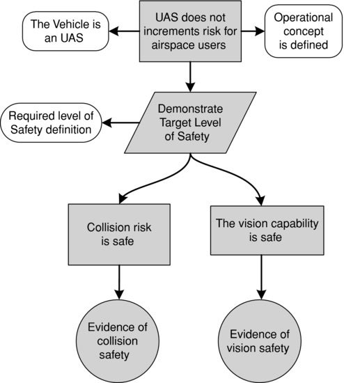
The principal regulatory bodies agree that one of the guiding principles for UAS regulation should be the equivalence with respect to manned aviation and therefore, regulatory airworthiness standards should be set to be no less demanding than those currently applied to comparable manned aircraft. This principle is known as the equivalent level of safety (ELOS) requirement and if we focus on the avoidance system, it means that the UAS must provide a method comparable to see and avoid requirements for manned aircraft. However, this concept also raises some criticism because of the difficulty of quantifying what exactly the ELOS requirement entails [2]. Conversely, another way to establish the ‘required safety’ is to directly specify the target level of safety (TLS) for UAS operations. In [13], both concepts are defined as follows:
- ELOS: an approximately equal level of safety that may be determined by qualitative or quantitative means.
- TLS: the acceptable mean number of collisions per flight hour which could result in fatalities by modelling the end-to-end system performance.
Numerous efforts have attempted to define the ELOS of current manned aircraft see and avoid functionality (i.e., quantifying the pilot's ability to visually detect hazardous objects or terrain and efficiently avoid them). For example, based on data from the US National Transportation Safety Board (NSTB), in [2] mid-air collision requirements are derived from fatality rates for accidents where an in-flight collision with obstacles or another aircraft occurred. According to this data, a maximum mid-air collision rate of 0.1 collisions per million flight hours is proposed for UAS. Another example is found in [1], where it is stated that SAA shall have an overall critical failure rate of no more then 0.51 per million of flight hours. This figure corresponds to the rate of general aviation mid-air collisions per year (considering a 10-year average) and was taken from the Aircraft Owners and Pilots Association (AOPA) analysis.
Conversely, the FAA proposes to establish a TLS for UAS, and in particular to further derive SAA requirements. As stated in [13], ‘the TLS approach should be the most likely to succeed, relative to the others considered. This approach is a very comprehensive end-to-end analysis that is traceable and quantifies the total risk of the system’. However, several issues should still be addressed before establishing how this value should be computed. For instance, when evaluating the collision risk for a UA flying through several airspace classes and altitudes, a decision must be made as to whether the TLS value needs to be met at every point in time or only on average across the duration of the entire flight. Moreover, it would also be reasonable to apply different TLS as a function of the intruder, this value being more stringent against cooperative aircraft than non-cooperative ones. As proposed in [13], a possible mechanism to take these considerations into account would be to apply different TLS requirements in different airspace classes.
In Figures 4.2 and 4.3, the concepts of ELOS and TLS are respectively represented by using a goal structured notation (GSN) [14]. This notation, widely used in safety case studies, consists of stating the goals that must be achieved by the system (squares), by relating them to the appropriate context and assumptions. As commented before, one of the main drawbacks of the ELOS approach is the difficulty of assessing the human perception and mid-air collision models, since several models and methodologies exist and none of them has been proved better than the others.
Figure 4.2 Safety representation of ELOS according to the goal structured notation
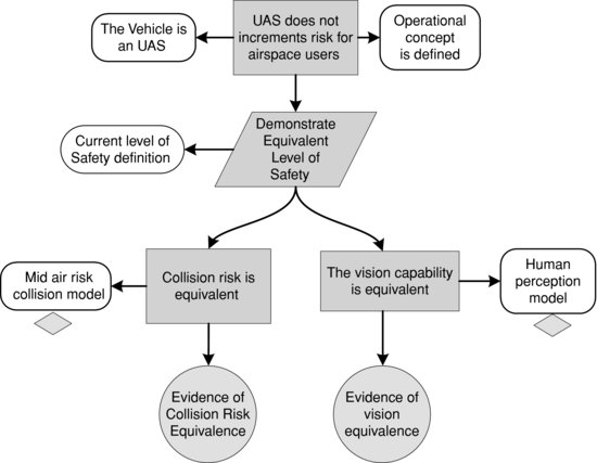
Figure 4.3 Safety representation of TLS according to the goal structured notation
Nevertheless, whatever the minimum safety rate is, and however acceptable the derived level of safety is considered, it must be translated into system reliability requirements. For example, in [8] a mid-air collision risk assessment is presented, aimed at estimating the number of expected collisions per hour of flight. This study would be useful when establishing the minimum performance requirements of SAA systems in different scenarios (see also [2]).
4.2 Existing Regulations and Standards
Conventional aviation regulations have been built, taking safety as the paramount objective and embracing personnel and organizations involved in the development, production and operation of the aircraft:
- The type certification of a specific model of aircraft is usually granted thanks to its development by a certified design organization, which ensures by its quality assurance process the appropriateness of its design to the applicable certification specification.
- The airworthiness of a specific unit is usually granted by the manufacture of a type certified aircraft in a certified production organization.
- The maintenance of the aircraft airworthiness must be done in certified organizations and by personnel certified in the maintenance of a particular aircraft model.
- The safety of each flight is ensured by the airworthiness of the aircraft plus the skills of also certified pilots, which are considered the last resort in emergency situations.
This broadly accepted certification structure assumes that there is always a human pilot onboard who could take control of the aircraft at any moment and consequently aviate the aircraft. This peculiarity does not affect significantly the maintenance of the airworthiness as the maintenance organization and its trained personnel will perform their duties following procedures developed during the design of the aircraft. This consideration is also applicable to the production organization, since they will produce aircraft that comply with the type certificate.
The design of an unmanned aircraft significantly changes the way the responsibility of fulfilling the aircraft functions is ensured by the systems to be included in the type certificate of the aircraft and the responsibilities assumed by the pilots, who are no longer onboard. In fact, certification specifications that can be fulfilled at present to obtain a type certificate assume that the flight crew and all aircraft control and management systems are located onboard, which is obviously not the case for UAS. The most significant issue is when implementing the aviate and navigation functions, since the flight crew and the onboard systems are physically separated and rely on a data communications link, introducing new failure modes related to the communication links, their performance and integrity, which are not present in manned aviation. Thus, the performance of the data link, and in particular the latency of the communications, could determine the impossibility of relying on the responsibility of the ground crew, requiring a new system to be compliant with the aircraft requirements. Poor data-link integrity could also make it impossible to meet the safety requirements of the system.
Similar considerations are found with collision-avoidance regulations. In [15] it is assumed that the human pilots are the last resort to ensure the safety of the flight, especially in VFR conditions. This assumption of responsibilities by human flight crews is reflected, for example, in the absence of collision-avoidance capable electronic systems for all aircraft types. ACAS might be the exception, but it should be noted that it is not mandatory for all aircraft and, for example, is almost inexistent in general and light aviation.
These responsibilities, completely assumed by the flight crew, are embraced by the see and avoid concept, which is the last resort to avoid collisions and eliminates the need or requirement for any airborne system. The dislocation of the flight crew when operating UAS will consequently introduce new capabilities in the onboard systems in order to meet the required levels of safety.
The actual implementation of these requirements, for the different UAS categories and architectures, shall contemplate different perspectives (such as the type of airspace, the automation level of the UAS, etc.). Therefore, systems compliant with the functions aviate, navigate and mitigate (notably, the collision-avoidance sub-function) are beyond the scope of the current regulations when talking about UAS, because the requirements to be fulfilled by these systems go beyond the requirements fulfilled by the equivalent systems in conventional aviation and regulations are explicitly designed for aircraft with onboard flight crew. However, there is significant interest in enabling UAS in civil airspace, due to the large amount of civil applications that go beyond emergencies and law enforcement (such as precision farming, infrastructure monitoring, communications relays, etc.) and therefore cannot operate in segregated airspace as military operations perform currently. Then, it is expected that missing regulations will come along with several experimental flights in which the different stakeholders could evaluate the impact of UAS in future aviation scenarios.
4.2.1 Current Certification Mechanisms for UAS
At present, and as considered by the different regulation bodies, two different mechanisms allow UAS to access the civil airspace, either by obtaining a restricted type certificate, along with an airworthiness certificate, or with a special permit to fly.
Conventional aviation shall satisfy different requirements to access civil airspace. Firstly, aircraft designs shall comply with the regulations of the corresponding safety agency (for example, the European Aviation Safety Agency (EASA), or the FAA in the USA), which recognizes this safe design by a type certificate. This certificate can be granted to all designs performed by an organization previously certified with a DOA (design organization approval) or by equivalent means. Then, each aircraft produced following the approved design acquires a certificate of airworthiness when manufactured by an organization certified with a POA (production organization approval) or that is able to show an equivalent product assurance. Furthermore, this certificate of airworthiness must be renewed according to a maintenance program performed by a certified maintenance organization.
The absence of a certification specification applicable to UAS designs leads to the impossibility of obtaining a type certificate and consequently a certificate of airworthiness. When the impossibility of applying an existing certification specification occurs, a restricted type certificate can be granted only under defined and limited conditions and providing that the actual conditions of use are restricted to those in which the certification specification applicability is not compromised. For example, in the case of UAS, if operations are assumed in segregated airspace there is no need to implement the SAA capability. Thus, a restricted type certificate allows an aircraft produced accordingly to obtain a restricted certificate of airworthiness which is valid only if the aircraft is operated according to the restrictions expressed in the restricted certificate type.
In case the aircraft cannot meet the previous certification requirements, but is still capable of performing a safe flight under defined conditions, a permit to fly can also be granted. This could be the case for the majority of UAS, since not many certification specifications exist for them yet. The conditions under which an aircraft is eligible for a permit to fly may be slightly different from country to country.
United States
The Federal Aviation Administration (FAA) has specific regulations to issue experimental certificates for the following subjects (FAR §21.191): research and development; showing compliance with regulations; crew training; exhibition; air racing; market surveys; operating amateur-built aircraft; operating primary kit-built aircraft; and operating light-sport aircraft under certain restrictions.
The special interest in UAS, along with their intrinsic characteristics, motivated the FAA to develop a joint interim procedure aimed at granting access to UAS into the US national airspace [16]. The following FAA groups were involved in the development of this document: the Unmanned Aircraft Program Office (UAPO) of the FAA Aircraft Certification Service (AIR-160); the Production and Airworthiness Division of the FAA Aircraft Certification Service (AIR-200); the Flight Technologies and Procedures Division of the FAA Flight Standards Service (AFS-400); and the FAA Air Traffic Organization's Office of System Operations and Safety (AJR-3).
This procedure describes how to obtain a special permit to fly, or more precisely a certificate of approval (COA) as named by the FAA. Thus, alternative methods are proposed to the conventional compliance of FAR Part 61, which tackles certification for pilots, flight and ground instructors; and Part 91, which deals with the general operating and flight rules. However, only US governmental institutions can apply for a COA, which includes some indications on airworthiness, flight operations and personnel qualifications. Non-governmental UAS developments must obtain a restricted airworthiness certificate, as explained above.
Moreover, in the procedure it is explicitly mentioned that current onboard cameras or sensors have not yet shown enough maturity to be considered as the only mitigation means to comply with the see part of the SAA requirements. The principal milestone is the difficulty of proving that non-collaborative aircraft can be conveniently sensed and the use of external observers or equivalent means (such as chase planes) is proposed in the procedure. The observers shall be located at a distance not bigger than 1 NM in the horizontal plane and 3000 ft vertically, except for operations in class A airspace, where UAS must comply with the required equipment to operate in this airspace while proving to be safe to any other user. The use of observers is forbidden for night operations, and a special safety case is required for such operations.
The use of SAA systems must be accompanied by a suitable safety case that shows its adequacy for the intended airspace. The design of such a system shall include the following sub-functions:
1. Detect – determine the presence of aircraft or other potential hazards.
2. Track – estimate the position and velocity (state) of a single intruder based on one or more surveillance reports.
3. Evaluate – assess the collision risk based on intruder and UA states.
4. Prioritize – determine which intruder tracks have met a collision risk threshold.
5. Declare – decide that action is needed.
6. Determine action – decide on what action is required.
7. Command – communicate and/or execute the determined action.
Europe
The EASA promotes the creation of standards and regulations for safe and environmentally friendly civil aviation in Europe. So far, EASA powers are vested in the regulation 216/2008 [17], which include: airworthiness (for DOA, POA and MOA), pilots licensing, operations approval, third-country operators and permits to fly. However, it must be noted that in the particular case of UAS, EASA has no authority on unmanned aircraft with an operating mass lower than 150 kg or on aircraft explicitly designed for research, experimental or scientific purposes. In these circumstances, permits to fly for UAS must be granted at national level, by the European member state where the UAS will carry on the operations.
In August 2009, EASA published its Policy Statement Airworthiness Certification of Unmanned Aircraft Systems [18], in which the agency assumed that more experience is still needed to publish a dedicated acceptable mean of compliance (AMC) document on UAS, as done with manned aviation. The interim proposal to achieve this required experience is to use the existing CS-21, sub-part B (type certificates) modified with some guidance, especially on special conditions according to the general means [19]. These special conditions refer to:
- emergency recovery
- capability
- command and control link
- level of autonomy
- human–machine interface
- control station
- due to type of operations
- system safety assessment.
Even with the importance of the sense and avoid (or detect and avoid as designated in [18]) for ensuring the safety of on-ground personnel, SAA is not considered to be an issue exclusive to UAS. EASA considers that the type certificate obtained by following its policy statement shall be accompanied by a statement in the aircraft flight manual limiting the operations to segregated airspace, unless the mitigation measures have been accepted by the responsible authority granting access to the airspace volume in which the UAS will operate. There exist numerous conditions under which an aircraft is eligible for an EASA permit to fly, for instance flight testing of new production aircraft; flying the aircraft for authority acceptance; exhibition and air show; or for non-commercial flying activity on individual non-complex aircraft or types for which a certificate of airworthiness or restricted certificate of airworthiness is not appropriate, among others.
Other Countries: Canada and Australia
Besides Europe and the United States, other countries are also working on the development of a regulatory framework for UAS operations. It is worth briefly mentioning the cases of Canada and Australia, which have special UAS working groups for that purpose.
In December 2006, the Canadian General Aviation branch convened a joint government and industry unmanned air vehicle (UAV) working group to review existing legislation and make recommendations for a regulatory framework for UAS operations. The UAV working group published a final report in September 2007 [20], with remarks that the working group will not address sense and avoid systems or requirements. However, in March 2010, the Canadian Civil Aviation branch established a program design working group [21] aimed at developing different deliverables from 2011 to 2016. One of the deliverables should particularly address new technologies, like SAA, which will enable new safety requirements to be achieved.
On the other hand, the Australian Civil Aviation Safety Authority (CASA) is represented on two standards committees: the RTCA Committee SC-203 and the ASTM F38.01. As mentioned in [22], ‘CASA is committed to the principles of harmonisation of regulations and standards with the FAA and EASA and will accept FAA and EASA UAV design standards when available’. Australian authorities already publish UAS-specific regulations in the Civil Aviation Safety Regulation (CASR) Part 101: Unmanned aircraft and rocket operations. Concerning the SAA system, in [23] it is stated that: ‘Unless the controller of a UAV is provided with sufficient visual cues to enable the acquisition and avoidance of other air traffic, UAV flights in controlled airspace will be treated as IFR flights, subject to ATC control. CASA may require a large UAV to be equipped with an SSR transponder, a collision avoidance system or forward looking television as appropriate for the type of operation.’
4.2.2 Standardization Bodies and Safety Agencies
The acceptable means of compliance issued by the different regulatory bodies relies on standards published by different standardization bodies. Usually those organizations constitute working groups in which the different actors involved in the activity or product to be standardized are represented. There exist many of these working groups, but perhaps the most representative ones, in terms of UAS regulations and SAA requirements, are:
- EUROCAE Working Group 73 (WG-73), which is addressing the standards required for civilian UAS to fly in non-segregated airspace. This group is sub-divided into four groups:
- SG-1: operations and sense and avoid.
- SG-2: airworthiness and continued airworthiness.
- SG-3: command and control, communications, spectrum and security.
- SG-4: UAS below 150 kg for visual line of sight operations.
- RTCA Special Committee 203 (SC-203), which is developing standards for UAS aimed at helping the safe, efficient and compatible operation of UA with other vehicles, based on the premise that UAS and their operations will not have a negative impact on the existing airspace users. One of their most relevant documents is a minimum aviation system performance standard (MASPS) for SAA for UAS, which at the moment of writing this book was still not complete.
- ASTM International Committee F38 on UAS, which is devoted to standards including the design, manufacture, maintenance and operation of UAS, as well as the training and qualification of personnel. A specific standard for the design and performance of an SAA system for UAS has been published in [1]. This committee is also divided into different sub-committees:
- F38.01 Airworthiness Standards.
- F38.02 Operations Standards.
- F38.03 Pilot & Maintenance Qualifications.
4.3 Sense and Avoid Requirements
In this section, we discuss the possible requirements for an SAA system for UAS, while pointing out the main issues that still need to be assessed. As already mentioned, some final requirements are not yet adopted by any regulation, but some organizations have already issued some documents. This section wraps up the available information at the moment this book was written and separates the SAA requirements into several categories.
4.3.1 General Sense Requirements
Sense functionalities in a wide approach include the detection of all the external hazards that might affect a given flight. Therefore, when operating UAS in a non-segregated airspace, it is necessary to consider that the vehicle will interact with an environment that is shared with other users. As a consequence, other aircrafts and airborne objects might be encountered and have to be detected. But, besides the detection of other flying objects, the sense systems should allow the monitoring of other hazards – for instance bad weather, wake turbulences or the proximity of terrain. Basic sense parameters which will have to be considered in the design phase of these systems are:
- The detection range of hazardous objects, which must allow the following avoidance manoeuvre to be executed with the sufficient time to result in the minimum required miss distance.
- The field of regard, being the area capable of being perceived or monitored by a sensor and which must demonstrate that the SAA system meets the right-of-way basic rules.
- Other parameters such as measurement accuracy, reliability and update rate [11].
Concerning the field of regard, right-of-way rules state that pilots must avoid all objects, with the exception of overtaking traffic, and according to [4] a horizontal azimuth angle of ±110° off the aircraft nose is recommended for visual scanning in manned aviation, and it is expected to be demonstrated for sense systems in UA. Furthermore, [1] proposes an angle of elevation of ±15° for UAS sense systems.
One of the main uses that the sense system will have is to avoid mid-air collisions. In that case, the UCAF (UAS collision avoidance function) must operate autonomously and independently from the ATM system or any other means of UAS separation provision [24]. Moreover, the sense system must detect cooperative and non-cooperative traffic and accommodate UAS operations in different flight modes and airspace classes. However, the system might rely in part on human intervention and the communications latency is an important factor to be assessed [9]. On the other hand, the detection of a collision threat shall be at a minimum range allowing a resolution manoeuvre resulting in a miss distance where both aircraft are well clear. Obviously, this minimum detection distance will depend greatly on the performances of the aircraft, such as the cruise speed, turn rate, climb or descent rates; and in the definition of the well clear term, which is discussed later on in this chapter. Furthermore, this detection shall be in all weather conditions that it is expected the UAV will encounter and even in case of loss of direct command, control or communications with the command ground station. Thus, it is of paramount importance to consider all these factors when designing the sense sub-system for the UAS.
The on-time detection of hazardous flying objects is a very challenging feature for the sense sub-system. Different techniques can be used in order to fulfil this objective and they are the subjects of intensive research. In [8], a classification of technologies that would be able to detect traffic is proposed, resulting in eight different categories including radar surveillance (see for instance [25]) or visual surveillance means (either by ground observers or chase planes).
Sensor technologies aim to meet or even exceed the performance of current human visual traffic detection. In 2003, NASA equipped a UA with a radar system able to detect non-cooperative targets and a traffic advisory system to detect cooperative ones. With this UA, and several surrounding traffic, some flight tests were carried out where SAA performance capabilities of the involved aircraft were varied [26, 27]. During the flight tests, the pilot's acquisition capabilities were also assessed, in order to be compared with the UAS sense capabilities. As reported in [8], only the traffic advisory system was sufficient for all encounter scenarios. The radar had a limited range of 4 miles detecting targets, being too late to perform appropriate avoidance manoeuvres. On the other hand, the human pilot's perception was between 1 and 1.5 nm. Further research showed that the human eye was inadequate to detect and prevent collisions in several situations and even limited sensors performed better than the human eye [26].
Obviously, the difficulty of detecting other flying objects will depend on the nature of these objects themselves. Nevertheless, not all possible hazardous objects are present in all situations and therefore, if UAS operations are restricted to a certain type of conditions (such as altitudes or airspace classes), the sense requirements will depend on the type of objects that the UA might encounter during its operation. In this context, a definition of the attributes of these potential threats becomes extremely import when developing a sense system. In the work done in [24], an exhaustive analysis was performed typifying all possible flying objects that may represent a threat of collision. Thence, 17 different categories are proposed, ranging from fauna, parachutists, kites and radio-controlled model aircraft to all types and sizes of aircraft. For each type of object it is explained under what conditions these objects may not be encountered, for example above certain altitudes, weather conditions or airspace classes. These categories are:
- F (Fauna): birds the size of a goose or larger, which do not generally fly in IMC or above 1000 ft AGL (above ground level). However, migrating birds can be encountered higher than this, typically in the range 5000 ft to 7000 ft AGL, often at specific times of year and in specific locations. Generally, the greater the height above the ground the less likely it is that birds will be encountered.
- K (Kites and tethered balloons): both the object itself and the cable connecting them to the ground. In general, operations above 400 ft should be notified by NOTAM.
- R (Radio-controlled model aircraft operated by hobbyists): generally operated in VMC below 400 ft AGL and within line of sight of the operator (typically 500 m). Operation above 400 ft should also be notified by NOTAM.
- B (Hot air balloons): which do not operate in IMC.
- D (Dirigible airships).
- G (Gliders): which do not operate in IMC.
- P (Parachutists): which are not usually present in IMC. Their activity is usually notified by NOTAM or known by the ATS.
- S (Powered air sports): such as very light aircraft, ultra-lights, motor gliders, motor paragliders, etc. Do not operate in IMC.
- A (Unpowered air sports): such as hang gliders, paragliders, etc. Do not operate in IMC.
- H (Helicopters): considering both civil and military.
- L (Light aircraft): such as non-pressurized general aviation.
- Q (Pressurized general aviation with a maximum take-off mass (MTOM) less than 5700 kg).
- M (Military fighters and high-performance jets).
- N (Pressurized passenger aircraft not required to carry ACAS).
- T (Pressurized passenger aircraft required to carry ACAS).
- C (Cargo aircraft or military air transport): generally with MTOM over 5700 kg and thus, expected to be ACAS equipped.
- U (Unmanned aircraft): a wide-ranging group covering a variety of sizes, airframe designs and capabilities.
All previous categories in turn can be grouped into five different categories of flying objects depending on their level of cooperation and capability to avoid a mid-air collision (see Table 4.3).
Table 4.3 Categorization of flying threatening objects as a function of their cooperativeness and avoidance capabilities
Categories 1 and 2 are the most challenging ones as the objects are non-cooperative, meaning that active sensors will be required to detect them. Objects of category 2 are able to avoid collisions in VMC and therefore, mitigation actions such as improving the UA visibility may be foreseen. Categories 3, 4 and 5 are cooperative and their detection can be performed more easily than with the others. On the other hand, an interesting factor to take into account is that the sense system shall detect intruders, but also identify them in order to comply with the right-of-way rules and decide which aircraft has the priority.
4.3.2 General Avoidance Requirements
After a collision threat has been conveniently sensed, the UA must select the appropriate avoidance manoeuvre and execute it. This manoeuvre must be compatible with the performance of the aircraft and remain below its structural and aerodynamic limits. These avoidance or resolution manoeuvres may include one or more of the following changes in the flight trajectory: airspeed, altitude or heading. If, as a consequence of an avoidance manoeuvre, the flight path deviates from an ATC clearance or instruction, it must be notified as soon as possible. Moreover, after the conflict is solved, subsequent manoeuvres must return the aircraft to the original flight plan or to a newly assigned flight path, while being compliant with the right-of-way rules.
The most basic requirement for the avoidance manoeuvre is to perform it in such a way that the distance from the intruder aircraft or object is equal to or greater than a minimum required miss distance. Current manned regulations state that the aircraft must remain well clear from the intruder and no explicit distances are given (see for example FAR §91.113). It is generally and implicitly understood that the minimum miss distance should be at least 500 ft in all directions [28]. However as reported in [29], the industry itself regards 500 ft of lateral separation as the worst-case minimum distance for SAA. Quoting this document, ‘the application of 500 ft. horizontal separation could generate a heightened sense of collision risk [and therefore, it is proposed] an increase in horizontal separation to 0.5 NM, [which] would reduce this perception and also the collision risk itself. […] These minima would only apply away from aerodromes.’ Yet, in [13], the term well clear is considered at separation level and not at avoidance level, since it is defined as the state by which two aircraft are separated in such a way that they do not initiate a collision avoidance manoeuvre. Therefore, according to this definition, this well clear boundary would vary as a function of the UA and intruder performances, conflict geometry, closure rates and relative accelerations.
Besides the actual value of this minimum miss distance or boundary, special consideration should be given to collaborative aircraft which will be equipped with ACAS, since the avoidance sub-system safety analysis must show compatibility with existing ACAS-II manoeuvres onboard some manned aircraft. In this context, coordinated manoeuvres can range from complex full 4D coordinated manoeuvres to only basic heading or altitude changes in the horizontal and vertical planes respectively. Carriage requirements for ACAS-II equipment are addressed in [30], where it is stated that ‘all turbine-engined aeroplanes of a maximum certificated take-off mass in excess of 5700 kg or authorized to carry more than 19 passengers shall be equipped with an airborne collision avoidance system (ACAS-II).’ The same document also recommends equipping all aircraft with such a system, while flight crew procedures for the operation of ACAS are found in [31] and procedures regarding the provision of air traffic services are described in [32]. For example, in [31] it is explained how pilots should react to ACAS advisories and some guidelines in the training of pilots are also given. Conversely [32] explains, for instance, how air traffic controllers should deal with ACAS equipped aircraft in case they deviate from the least clearance due to a resolution advisory. In both documents, phraseology in the operation of ACAS is also described.
RTCA minimum operational performance standards (MOPS) for TCAS-II are found in [33] and could be applied to UAS to some extent. For instance, and as [11] already points out, TCAS-II assumes typical transport category aircraft performance for collision avoidance and resolution advisories (RAs) algorithms, while many UAS may not be capable of the same performance characteristics. Moreover, RAs are executed by pilots in manned aircraft and if RAs are executed autonomously by a UA system, this increases the safety requirements on the system. Conversely, if a UA operator executes a RA, issues of data-link latency and reliability must be addressed.
Unusual UAS performance (compared with transport category aircraft) must also be assessed from the ATC point of view, since current ATC practices and training are based on current existing manned aircraft. For example, some UA are able to fly at high altitudes comparable with current manned commercial aviation, but their rate of climb is dramatically lower than modern airliners. Therefore, UA performances will have to be included in ATC handbooks in order to be able to accommodate UA and provide safe and efficient separation and traffic information services. Moreover, it should be noted that foreseen UAS SAA systems will also support self-separation functions and consequently, some responsibility could eventually be shifted from ATC to UAS (as is also foreseen in manned aircraft [34]).
Concerning terrain avoidance, some systems exist in manned aviation such as the terrain avoidance warning system (TAWS) or the ground proximity warning system (GPWS). However, these systems are advisory in nature and as we observed with the resolution advisories of the TCAS-II, the onboard pilot has the ultimate responsibility to execute the avoidance manoeuvre. Therefore, existing standards will also need to be updated in order to address remote pilot operations and/or UAS automation to avoid terrain [11].
Finally, avoidance means must also be designed to comply with visibility and cloud clearance criteria (with specific requirements depending mainly on the airspace class) for the UA to be seen by other aircraft and therefore comply with the flight rules. Besides SAA requirements, severe weather could result in damage to the UAS and affect its airworthiness and must therefore be detected and avoided.
Summing up, avoidance design parameters should take into consideration several factors, such as weather, terrain and flying objects. Traffic avoidance design will depend mainly on the minimum miss distance from the intruder aircraft, actual aircraft performances and limitations, a correct interpretation and implementation of the right-of-way rules, the collision avoidance capabilities of the intruder and the compatibility with the ATC clearances.
The next sub-sections focus on the particularities that different airspace classes, altitudes of operation and weather conditions, UAS communications data links and automation levels may have on the requirements for a safe design of SAA system.
4.3.3 Possible SAA Requirements as a Function of the Airspace Class
The type of airspace where UAS operations will be carried out will mainly determine the level of cooperativeness of the other traffic and the availability of ATC for assuring separation or enhancing the situational awareness with respect to other traffic. It is possible to aggregate the types of airspace into two large categories, as proposed in [24]: those airspaces where all aircraft are cooperative; and the remaining ones where some of the aircraft may not be cooperative. As mentioned in Section 4.1.2, the specific requirements for each airspace class may differ slightly from one country to another. Yet, in airspace classes A to D it is in general required to operate with a transponder. Moreover, it is also quite usual to mandate the use of a transponder above a certain altitude regardless of the airspace class. For example, in the USA transponders are required in airspace classes A, B, C and E above FL100, although some aircraft are exempted (FAR §91.215). The RTCA MOPS for transponders are found in [35], which specifies some requirements for the flight crew control and monitoring of the operation of the transponder that could be sufficient for the application in UAS, while other requirements may be sufficient for UAS.
The signal emitted by aircraft transponders is received by secondary surveillance radars (SSR) and the derived aircraft positions are enhanced with the information encoded in those signals. Thus, a mode A transponder transmits just a five-digit identifier, while a mode C transponder also transmits the barometric altitude of the aircraft. The newer mode S transponders [36] have the capability to transmit even more information, such as the position of the aircraft if an ADS-B system is present. All this information is presented in the ATC positions.
Besides ATC stations, ADS-B allows aircraft and ground vehicles to send or receive surveillance information, including an identifier, latitude, longitude and altitude. Therefore, the flight crew situational awareness is significantly improved and some separation responsibilities can eventually be shifted from the ATC to the flight crew. However, ADS-B is not currently mandated and different data-link technologies exist (other than mode S transponders) and are standardized in documents [37, 38], while the data-link-independent standard for ADS-B systems is published in [39].
Besides SSR detection, transponders are the base technology for current implementations of the TCAS. Obviously, TCAS (or more generally ACAS) equipped aircraft will be easier to detect and, if the UA is equipped with such a system, the generated traffic alerts would increase the situational awareness of the UAS flight crew and improve the sense capabilities. The TCAS-I standard is published in [40], while relaxed requirements can be found in [41] if only the traffic advisory airborne equipment is implemented. This could reduce the cost of such a system with respect to a TCAS-I and could be useful for certain UAS implementations. As explained before, TCAS-II implements resolution advisories too, but the way these derive into effective avoidance manoeuvres for UAS still remains an open issue.
It is worth mentioning that UAS usually perform a type of flight which is different from the one performed by the majority of commercial aviation. In the majority of cases, UAS will be used to perform missions that might include holding, scans and other non-conventional procedures whilst commercial aviation mainly operates a point-to-point flight, the carriage of people and goods being its main purpose. Therefore, commercial aviation uses airways to fly from one point to another. This leads to a situation where the probability of a mid-air collision is higher flying on those airways and in their vicinity than flying away from them. Therefore, as computed in [8], the mid-air collision risk outside the main congested airways and areas might be low enough to allow a reduction in the performances needed to detect and avoid other traffic.
4.3.4 Possible SAA Requirements as a Function of the Flight Altitude and Visibility Conditions
Some systems operate in a given range of altitudes, and if the UA is flying outside these altitudes it is not likely to encounter them. In a similar way, the weather conditions (VMC or IMC) will affect the capabilities of some sensors, for example those based on vision, but will also affect the type of hazardous objects that might be encountered (i.e., with bad visibility the UA will not collide with a glider as they do not operate in IMC conditions). These dependencies are analysed in [24] and summarized in Table 4.4, where for each category of objects the likelihood of finding them in certain altitudes and meteorological conditions is given.
Table 4.4 Category of objects that may be found as a function of the flying altitude, meteorological conditions and traffic environment (from [24])
As mentioned before, transponders are generally mandated for aircraft evolving above FL100 and that is why in this table a clear separation as a function of this altitude appears. Besides the fact that this requirement is not enforced in all countries, it should also be noted that even in those countries where it is applied, some exemptions may apply (for example, gliders flying above FL100 and not equipped with a transponder). On the other hand, below FL100 aircraft are usually limited to speeds below 250 kt in the majority of airspace classes (depending on the country, classes A and B are usually exempt from this speed limitation). Therefore, Table 4.4 shows the most common situations providing that some exemptions may exist as a function of the national regulations. Moreover, it is worth mentioning that even if some objects are not likely to be found above a certain altitude (such as fauna or light aircraft), the UAS may encounter them during its climb and descent phases. Nevertheless, some possible solutions allowing a less demanding SAA system would be to temporarily segregate some airspace to fit these climb and descent phases; use chase aircraft following the UA during these phases; climb/descend in a controlled airspace class with a completely known environment for the ATC, while avoiding overflying populated areas to reduce the risk of a crash due to a potential collision with fauna, etc.
4.3.5 Possible SAA Requirements as a Function of the Type of Communications Relay
Latency of the communications with the ground control could determine the performance of the systems onboard. Since nobody questions the presence of a human controlling the UAS, the distance between pilot and aircraft could introduce delays that may threaten certain SAA architectures or solutions. This latency includes: communication delays, SAA scan rates, onboard and ground processing times of the different algorithms involved, pilot-in-the-loop reaction times and coordination with ATC. Two main categories exist when talking about command, control and telemetry communications: those which are at line of sight with the UAS and those beyond line of sight.
Line of Sight Communications
Line of sight operations have no visual obstacles between the flight crew and the UA and the range between them can vary from a few metres to tens of nautical miles. For short distances (up to a few miles), the visual contact with the UA that can establish the flight crew on ground could even justify the absence of onboard means to sense the traffic. For greater distances, the visual performance of the flight crew along with the reduction of the spatial situational awareness will not be able to fulfil the sense requirements and other support systems will be required. Moreover, the orography is an important factor to consider when operating in line of sight conditions, since some traffic could be hidden behind the terrain. Therefore, not only is it required to have visibility of the UA, but also of the surrounding airspace where threatening traffic may exist.
Small latencies in line of sight conditions could even allow a direct video link from the UA to the flight crew. This video link and the assumption of responsibility by the flight crew when assessing the situation, elaborating the evasive actions and performing them simplifies the whole SAA system. However, the data link itself remains a critical component and the exigencies over real-time performances would be very demanding.
Beyond Line of Sight Communications
An aircraft beyond line of sight impedes the assumption of sensing responsibility by the flight crew exclusively. It is worth mentioning that these kinds of operation do not always imply a far location from the ground control station. For example, the flight crew could be located on one side of a building controlling a UA performing a perimeter surveillance of the same building. Since there is not a straight obstacle-free line between the UA and the flight crew for the entire mission, this operation would be considered beyond line of sight. Different communication strategies are foreseen for these types of operation and are summarized as follows:
- Direct radio frequency (RF) communications. Even if the UA is beyond line of sight, RF communications can be successfully implemented under some conditions. These architectures provide fast links and latency is not deemed a big issue for SAA applications. However, the frequency employed for these communications could suffer from insufficient bandwidth, especially if video is transmitted aimed at implementing the sense function on the ground station.
- Terrestrial networks. This architecture externalizes part of the communications to a service provider that already owns a dedicated network over a certain area. With this architecture, the bandwidth limitations depend on the actual means of the provider and sense and avoid video architecture will be conditioned to this available bandwidth, the latency of the data transmission and the stability of the communications. Thus, depending on the quality of service (QoS) guaranteed by the provider, a strategy for SAA including video transmission could be considered or discarded as a function of the real-time performance and integrity of the network.
- Satellite communications. These kinds of communication introduce large latencies because of the long distances that communication signals must travel. These delays mean the SAA functionality to be performed entirely onboard the UA.
4.3.6 Possible SAA Requirements as a Function of the Automation Level of the UAS
As commented before, the degree of automation of the UAS is also a key factor in the SAA capability, since highly automated platforms will need more reliable sense sub-systems than those with a high contribution of the human crew and, therefore, closer to manned aviation see and avoid performance.
Therefore, the level of autonomy envisaged for the UAS could notably simplify the requirements for the SAA system. During the phase of the allocation of aircraft functions to systems [42], the abstract functionality of the aircraft is divided between the flight crew and the automated systems supporting each of the functionalities. As a function of the level of responsibility assumed by the flight crew, we can establish four levels of automation:
- Radio-controlled aircraft: in this situation, the pilot directly commands the attitude of the aircraft by controlling the flight surfaces through a dedicated radio control system. As the aircraft itself has no means to autonomously modify its trajectory, all avoidance manoeuvres will be performed exclusively by the human pilot and therefore all sense information must be available to this pilot in real time.
- Pilot in line: this architecture allows the aircraft to follow programmed flight plans but allowing the pilot to take control of the aircraft and aviate it at any time. Since the flight crew retains the capability of assuming control of the trajectory, the responsibility of the SAA functions can be shared by systems and humans.
- Pilot on line: here the pilot has the capability to take control of the UA but only to navigate it, the aviation function being performed autonomously. The difference between allowing the flight crew to directly aviate or navigate the aircraft may seem subtle, but has an enormous implication in SAA systems. Aviate is defined as modifying the trajectory of the aircraft by controlling its attitude in real time. Whereas navigate means to give guidance inputs to the aircraft (in the form of headings or even waypoints, for example) aimed at also modifying the flight path. Therefore, the time scale for pilot on line operations is significantly larger than in previous categories and as a consequence it is likely that SAA systems would be built onboard and the UA would assume the entire responsibility for sensing and performing avoiding manoeuvres.
- Full autonomous UAS: full autonomy shall be understood as the capacity of the UA to achieve its entire mission without considering any intervention of the human flight crew. Obviously, with this architecture the SAA must be performed exclusively by onboard means. Nevertheless, these kinds of operation are still not contemplated by any regulatory body in the world.
4.4 Human Factors and Situational Awareness Considerations
Although it might be technically feasible to build up a SAA system which operates completely autonomously and without reporting traffic and decisions taken to the UAS flight crew, it would be advisable for the pilot in command to have access to any traffic information sensed and the separation or collision avoidance manoeuvres carried out by the UA. This would help to validate the correct operation of the SAA system, enhance the situational awareness of the flight crew and allow them to report traffic to ATS, if necessary. This means that some human–machine interfaces (HMIs) should be developed to present all the necessary information to flight crew.
As a general statement in aviation, the more information the flight crew have access to, the higher the situational awareness is, and the ‘thicker’ the different safety layers are. However, presenting more information to the operator can also lead to problems such as cognitive overload. Perhaps using contextual information is one of the solutions to cope with this problem, but no real experience exists so far with these kinds of HMI, since most of the analyses are currently limited to UAS operating under military conditions. Therefore, the definition of these interfaces, along with all the human factors derived from the involvement of the flight crew in the SAA process, is also the subject of intense ongoing research and standardization processes.
In manned aviation, we already find some interfaces that enhance the see and avoid capabilities of the pilots. At collision avoidance level, ACAS systems must notify aircraft crew about possible conflicts. As mentioned earlier, the most basic ACAS systems trigger traffic alerts in case of potential conflict with another cooperative aircraft (such as the TCAS-I), while others can also provide the pilots with resolution advisories. These systems interface with the cockpit indicators or displays, being the navigation display (ND) of modern aircraft used for showing the surrounding traffic; and the primary flight display (PFD) for traffic alerts and resolution advisories indications. Current ASAS developments and prototypes propose the use of a cockpit display traffic information (CDTI), which in some cases could be implemented on upgraded versions of current navigation display concepts. A CDTI is also meant to present surveillance information about the surrounding traffic, but with a larger scope than ACAS implementations, allowing in this way to perform separation functions onboard. Thus, the information presented may include relative positions of other aircraft gathered from ACAS, ADS-B systems, traffic information services (TIS) and, in short, all traffic information sensed by the UAS SAA system(s).
Technically speaking, the ‘cockpit’ does not exist in a UAS, as the onboard location where flight control is conducted by flight crew. Yet, similar displays and with the same philosophy as CDTIs will certainly be found in the UAS control ground station. The RCTA document DO-243 [43] contains guidance material for the implementation of a CDTI and a few basic features and capabilities are provided (for example, formats for surrounding aircraft identification, closure rates, ground speed information, ground track indicator, target selection, traffic alert, etc.). Even if this standard refers to the cockpit of manned aircraft, it would easily be applicable to UAS ground stations since the focus is given on the presentation to the flight crew. On the other hand, [44] presents some ASAS applications by using CDTI interfaces. Some of them would also be directly applicable to UAS, while others would need some minor or major modifications (like, for example, for all the applications aimed at improving situational awareness of the flight crew when performing visual self-separation operations). Some high-level definitions and specifications on ASAS applications are given in the RTCA MASPS Do-289 [45], while document [46] focuses on ADS-B specific applications. On the other hand, TIS-B messages are standardized in [47] and interchange standards for terrain, obstacle and aerodrome data are found in [48].
As already observed in [11], all the above-mentioned standards and discussions are general enough to apply to most UAS applications and these documents would undoubtedly be an excellent starting point for UAS regulations and standards. Yet, there is still the need to particularize for UAS, especially when dealing with critical issues such as signal quality, data latency, overall integrity and interaction with the crew. For example, current experimental UAS platforms only address the way in which the surrounding traffic is displayed to the UAS crew. However, they do not address critical issues like how to report the best reaction strategy to the crew; or how to provide support to the potential instructions that the ATC may deliver. All these elements are still under research, with little or no experience available.
4.5 Conclusions
In conventional aviation, see and avoid is the capacity of the human crew to detect other threatening objects or terrain and perform evasive actions to avoid a loss of separation and collisions as a last resort. In fact, all current regulations in aviation assume the presence of a human pilot onboard who could take control of the aircraft at any moment. UAS try to go beyond this limitation by removing the human from the aircraft, which somehow remains on the loop. The equivalent sense and avoid for UAS is one of the principal pitfalls in their way of performing normal operations in civil and non-segregated airspace. However, there is no regulation about SAA yet, since this functionality is specific to UAS, whose operations are at present not fully regulated in non-segregated airspace. Nevertheless, the big interest in UAS technologies demonstrated by military agencies in recent years, as well as the amount of applications in which such a technology seems to be beneficial, have pushed the regulatory bodies to start the regulation process for UAS. Yet, this process is very complex, since it needs agreement between actors with possible conflicting interests; for example, private aviation willing to fly with the minimum possible required avionic equipment versus highly technological and automated UAS operations, companies offering aerial services with UAS versus ATC conventional practices, etc.
In this chapter an overview of existing regulations and their limitations regarding SAA has been given. The principal factors that would determine future SAA requirements have been identified: class of airspace, altitude and visibility conditions, type of UA communication relay and UAS automation level. From this analysis, a significant paradox arises when regarding the sense capability: large UA will in general be required to detect fewer types of object because of their usual altitude of operation, airspace class and visibility conditions. This is a direct implication of the fact that large platforms usually perform missions at high altitudes where terrain and fauna are not an issue and other flying aircraft are all cooperative and known by the ATC. On the other hand, very small UAS will definitely evolve in a very challenging environment, with non-cooperative flying aircraft, fauna and ground obstacles. However, some collisions might not be a real threat for humans since these platforms have a really small weight and kinetic energy. Therefore, the risk of fatalities in some operational scenarios (such as in line of sight and away from populated areas) would be well below the required safety levels. Then, since the UAS spectrum covers a great variety of UA sizes, airframe designs, capabilities and mission particularities, the particular requirements for their SAA system will be strongly related to all these variables.
Furthermore, some issues around SAA systems still linger. For example, there exists the need to define the minimum requirements on minimum detection distances/times and aircraft separation margins; along with minimum avoidance distances/margins and efficient deconfliction algorithms to replace pilot action. The main reason for this is the non-specificity of the ‘well clear’ term which sets the basis for current manned aviation regulations, allowing for a pilot's subjective assessment on their actions but not being valid for designing an engineering solution meeting the SAA requirements. Moreover, collision avoidance must be regarded as a last resort capability to prevent an imminent collision and consequently a separation function is also required. Again, the minimum separation values are not always objective and are difficult to quantify with present regulations. On the other hand, cooperativeness in SAA systems should be addressed when considering UAS since not all airspace users are (or will be) equipped with transponders, ADS-B based systems or ACAS. Moreover, even current ACAS implementations will not be valid for some UAS, since they assume that avoidance manoeuvres could be performed with performances typical of transport category aircraft.
It seems obvious that SAA functions will be necessary for future UAS operations in civil non-segregated airspace, being one of the most important systems since SAA malfunction will represent a flight critical emergency. However, SAA requirements cannot be the same for all UAS, because of the great variability of platforms, systems and missions. It is true that UAS integration in civil airspace should not incur any cost to current airspace users [49], but it is also true that the UAS should pose no greater risk to persons or property than other current airspace users and therefore, requirements and regulations will be expected to adapt to the specificities and particularities of this promising and exiting new chapter in the history of aviation.
Acknowledgments
This work has been partially funded by Ministry of Science and Education of Spain under contract CICYT TIN 2010-18989. This work has been also co-financed by the European Organization for the Safety of Air Navigation (EUROCONTROL) under its CARE INO III programme. The content of the work does not necessarily reflect the official position of EUROCONTROL on the matter.
References
1. ASTM International, ‘Standard Specification for Design and Performance of an Airborne Sense-and-Avoid System’, American Society of Testing & Materials, Document F2411-07, February 2007.
2. Dalamagkidis, K., Valavanis, K.P., Piegl, L.A., and Tzafestas, S.G. (eds), On Integrating Unmanned Aircraft Systems into the National Airspace System: Issues, Challenges, Operational Restrictions, Certification and Recommendations, Vol. 26 of International Series on Intelligent Systems, Control, and Automation: Science and Engineering, Springer-Verlag, Berlin, 2009.
3. ICAO, Annex 10 to the convention on international civil aviation – Aeronautical Telecommunications. Volume IV – Surveillance radar and collision avoidance systems, 2nd edn, International Civil Aviation Organisation, Montreal (Canada), 1998.
4. ICAO, Annex 2 to the convention on international civil aviation – Rules of the air, 9th edn, International Civil Aviation Organisation, Montreal (Canada), 1990.
5. ICAO, Annex 11 to the convention on international civil aviation – Air traffic services, 13th edn, International Civil Aviation Organisation, Montreal (Canada), 2001.
6. Eurocontrol, ‘Implementation of the Airspace Strategy Task Force A (IAS-TFA)’, available at http://www.eurocontrol.int/airspace/public/standard_page/17111_IASTFA.html (last checked January 2011).
7. UK Civil Aviation Authority (CAA), CAP 722 Unmanned Aircraft System Operations in UK Airspace – Guidance, 2010.
8. Weibel, R.E. and Hansman, R.J., ‘Safety Considerations for Operation of Unmanned Aerial Vehicles in the National Airspace System’, Technical report, MIT International Center for Air Transportation, March 2005.
9. RTCA, ‘Operational Services and Environmental Definition (OSED) for Unmanned Aircraft Systems (UAS)’, Radio Technical Commission for Aeronautics, Document Do-320, Washington, DC, June 2010.
10. NASA, ‘Potential use of unmanned aircraft systems (UAS) for NASA science missions’, National Aeronautics & Space Administration, 2006.
11. RTCA, ‘Guidance material and considerations for unmanned aircraft systems’, Radio Technical Commission for Aeronautics, Document Do-304, Washington, DC, March 2007.
12. UAVNET, ‘European civil unmanned air vehicle roadmap, volumes 1 and 2’, available at http://www.uavnet.com, 2005.
13. FAA, ‘Sense and Avoid (SAA) for Unmanned Aircraft Systems (UAS)’, Federal Aviation Administration sponsored Sense and Avoid Workshop, Final report, October 2009.
14. Weaver, R.A. and Kelly, T.P., ‘The goal structuring notation – a safety argument notation’, Dependable Systems and Networks, Proceedings of Workshop on Assurance Cases, July 2004.
15. Hayhurst, K.J., Maddalon, J.M., Miner, P.S., Szatkowski, G.N., Ulrey, M.L., DeWaltCary, M.P., and Spitzer, R., ‘Preliminary considerations for classifying hazards of unmanned aircraft systems’, February 2007.
16. FAA, ‘Interim Operational Approval Guidance,08-01: Unmanned Aircraft Systems Operations in the U.S. National Airspace System’, Federal Aviation Administration, Aviation Safety Unmanned Aircraft Program Office, AIR-160, March 2008.
17. European Parliament, ‘Regulation (EC) No. 216/2008 of the European Parliament and the Council of 20 February 2008 on common rules in the field of civil aviation and establishing a European Aviation Safety Agency and repealing Council Directive 91/670/EEC, Regulation (EC) No. 1592/2002 and Directive 2004/36/EC’, Official Journal of the European Union, February 19, 2008.
18. EASA, ‘Policy Statement Airworthiness Certification of Unmanned Aircraft Systems (UAS)’, European Aviation Safety Agency, August 2009.
19. EASA, ‘Acceptable means of compliance and guidance material to Part 21’, decision no. 2003/1/RM, October 2003.
20. Transport Canada Civil Aviation, ‘Unmanned Air Vehicle (UAV) Working Group Final Report’, September 2007, available at: http://www.tc.gc.ca/eng/civilaviation/standards/general-recavi-uavworkinggroup-2266.htm.
21. Transport Canada Civil Aviation, ‘Unmanned Air Vehicle (UAV) Systems Program Design Working Group’, March 2010, available at: http://www.h-a-c.ca/UAV_Terms_of_Reference_2010.pdf.
22. Carr, G., ‘Unmanned aircraft CASA regulations’, Civil Aviation Safety Authority (CASA), Australia, on-line presentation available at: http://www.uatar.com/workinggroups.html.
23. CASA, ‘Unmanned aircraft and rockets. Unmanned aerial vehicle (UAV) operations, design specification, maintenance and training of human resources’, Civil Aviation Safety Authority, Advisory Circular 101-01(0), Australia, July 2002.
24. Eurocontrol, Unmanned Aircraft Systems – ATM Collision Avoidance Requirements, Edition 1.3, May 2010.
25. Wilson, M., ‘A mobile aircraft tracking system in support of unmanned air vehicle operations’, Proceedings of the 27th Congress of the International Council of the Aeronautical Sciences, ICAS, Nice, France, September 2010.
26. Wolfe, R., ‘NASA ERAST non-cooperative DSA flight test’, Proceedings of the AUVSI Unmanned Systems Conference, Baltimore, MD, July 2003.
27. Schaeffer, R.J., ‘A standards-based approach to sense-and-avoid technology’, AIAA 3rd ‘Unmanned Unlimited’ Technical Conference, Workshop and Exhibit, Chicago, IL, September 2004, Paper AIAA 2004-6420.
28. FAA Order 8700.1, Change 3, Chapter 169, §5A.
29. Eurocontrol, ‘Eurocontrol specifications for the use of military unmanned aerial vehicles as operational air traffic outside segregated airspace’, Document SPEC-0102, July 2007.
30. ICAO, ‘Annex 6 to the Convention on International Civil Aviation – Operation of Aircraft, Part I – International Commercial Air Transport – Aeroplanes’, 8th edn, International Civil Aviation Organisation, Montreal, Canada, 2001.
31. ICAO, ‘Procedures for Air Navigation Services. Aircraft Operations, Volume I – Flight Procedures’, 5th edn, International Civil Aviation Organisation, Montreal, Canada, 2006, Document 8168.
32. ICAO, ‘Procedures for Air Navigation Services. Air Traffic Management’, 14th edn, International Civil Aviation Organisation, Montreal, Canada, 2001, Document 4444.
33. RTCA, ‘MOPS for traffic alert and collision avoidance system III (TCAS II) airborne equipment’, Radio Technical Commission for Aeronautics, Washington, DC, December 1997, Document Do-185A.
34. Eurocontrol, ‘Review of ASAS applications studied in Europe’, Technical Report, CARE/ASAS action, CARE/ASAS activity 4, February 2002, available at: http://www.eurocontrol.int/care-asas/gallery/content/public/docs/act4/care-asas-a4-02-037.pdf.
35. RTCA, ‘Minimum operational characteristics – airport ATC transponder systems’, Radio Technical Commission for Aeronautics, Washington, DC, October 2008, Document Do-144A.
36. RTCA, ‘Minimum operational performance standards (MOPS) for air traffic control radar beacon system/mode select (ATCRBS/mode S) airborne equipment’, Radio Technical Commission for Aeronautics, Washington, DC, February 2008, Document Do-181D.
37. RTCA, ‘MOPS for 1090 MHz extended squitter automatic dependent surveillance – broadcast (ADS-B) and traffic information services – broadcast (TIS-B)’, Radio Technical Commission for Aeronautics, Washington, DC, February 2009, Document Do-260B.
38. RTCA, ‘MOPS for universal access transceiver (UAT) automatic dependent surveillance – broadcast (ADS-B)’, Radio Technical Commission for Aeronautics, Washington, DC, February 2009, Document Do-282B.
39. RTCA, ‘Minimum aviation system performance standards for (MASPS) for automatic dependent surveillance broadcast (ADS-B)’, Radio Technical Commission for Aeronautics, Washington, DC, June 2002, Document Do-242A.
40. RTCA, ‘MOPS for an active traffic alert and collision avoidance system I (Active TCAS I)’, Radio Technical Commission for Aeronautics, Washington, DC, December 1994, Document Do-197A.
41. FAA, ‘Technical Standard Order (TSO) C147, Traffic advisory system (TAS) airborne equipment’, Federal Aviation Administration, Department of Transportation, Aircraft Certification Service, Washington, DC, April 1998.
42. SAE, Guidelines for Development of Civil Aircraft and Systems, Society of Automotive Engineers, Standard ARP4754-A, December 2010.
43. RTCA, ‘Guidance for initial implementation of cockpit display of traffic information’, Radio Technical Commission for Aeronautics, Washington, DC, February 1998, Document Do-243.
44. RTCA, ‘Applications descriptions for initial cockpit display of traffic information (CDTI) applications’, Radio Technical Commission for Aeronautics, Washington, DC, September 2000, Document Do-259.
45. RTCA, ‘Minimum aviation system performance standards (MASPS) for aircraft surveillance applications (ASA)’, Radio Technical Commission for Aeronautics, Washington, DC, September 2003, Document Do-289.
46. RTCA, ‘Development and implementation planning guide for automatic dependent surveillance broadcast (ADS-B) applications’, Radio Technical Commission for Aeronautics, Washington, DC, June 1999, Document Do-249.
47. RTCA, ‘Minimum aviation system performance standards (MASPS) for traffic information service – broadcast (TIS-B)’, Radio Technical Commission for Aeronautics, Washington, DC, October 2007, Document Do-286B.
48. RTCA, ‘Interchange standards for terrain, obstacle, and aerodrome mapping’, Radio Technical Commission for Aeronautics, Washington, DC, February 2009, Document Do-291A.
49. Gonzalez, L.-F., Australian Research Centre of Aerospace Automation. Unmanned Aircraft Systems, the Global Perspective 2009/2008, 2007, pp. 17–18.