
10
See and Avoid Using Onboard Computer Vision
10.1 Introduction
10.1.1 Background
The integration of unmanned aircraft into civil airspace is a complex issue. One key question is whether unmanned aircraft can operate just as safely as their manned counterparts. The absence of a human pilot in unmanned aircraft automatically points to a deficiency – that is, the lack of an inherent see-and-avoid capability. To date, regulators have mandated that an ‘equivalent level of safety’ be demonstrated before UAVs are permitted to routinely operate in civil airspace. This chapter proposes techniques, methods, and hardware integrations that describe a ‘sense-and-avoid’ system designed to address the lack of a see-and-avoid capability in unmanned aerial vehicles (UAVs).
10.1.2 Outline of the SAA Problem
Non-cooperative collision avoidance (or sense-and-avoid) for UAVs has been identified as one of the most significant challenges facing the integration of unmanned aircraft into the national airspace [1, 2]. Here, the term ‘sense’ relates to the use of sensor information to automatically detect possible aircraft conflicts, whilst the term ‘avoid’ relates to the automated control actions used to avoid any detected collisions. Much of the previous research effort on the sense-and-avoid problem has been focused on the ‘sense’ or conflict detection aspect of the problem. This is so because, under a crude interpretation of the issues, once a conflict has been ‘sensed’, the ‘avoid’ aspects of the problem can be almost routinely achieved through any aircraft manoeuvre that substantially changes heading [3].
10.1.2.1 Collision-Course Geometry
Many authors have reported that a mid-air collision between aircraft travelling with constant velocity occurs when two aircraft are converging with constant bearing [4, 5]. This bearing condition is illustrated in Figure 10.1.
Figure 10.1 Constant bearing between aircraft leads to a collision
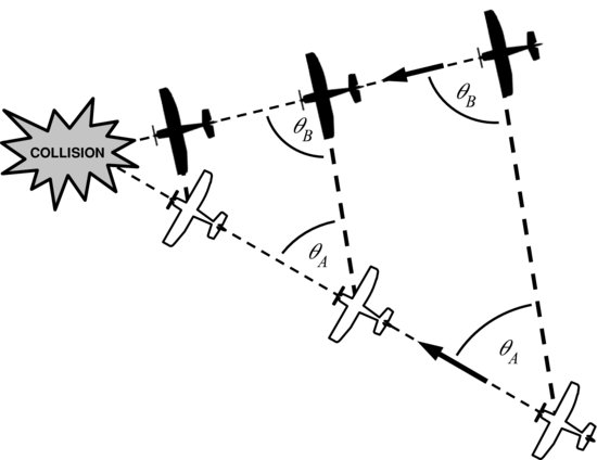
From the perspective of the pilot in the dark aircraft, the light aircraft appears as a stationary feature through the windscreen, and vice versa [6]. This unique dynamic can be exploited by collision warning systems to identify aircraft that are on a potential collision path. For example, a vision-based warning system would perceive objects on a collision course as relatively stationary features on the image plane. Objects that are moving rapidly across the image plane can be discounted as genuine threats. This chapter will focus on target detection, tracking, and avoidance techniques that exploit this constant bearing property of collision-course aircraft.
10.2 State-of-the-Art
An automated sense-and-avoid system is desirable for airborne vehicles to protect them from potential collision with other aircraft. The following review discusses some of the existing technologies that have been used to address this need, as well as providing an overview of emerging techniques that tackle the sense-and-avoid problem through vision-based approaches.
There is a wide variety of possible ‘sensing’ options, and these options are usually divided into the cooperative and non-cooperative approaches. Cooperative sensing approaches are those involving the mutual sharing of location information as is done in Traffic-alert and Collision Avoidance System (TCAS) transponders [7]. On the other hand, non-cooperative approaches involve directly sensing other aircraft, irrespective of the other aircraft's desire to be sensed. Cooperative approaches such as TCAS are not a completely satisfactory solution to the sense-and-avoid problem because the protection offered by such approaches is dependent on the desire and ability of other aircraft to share information. Since January 2003, the International Civil Aviation Organisation (ICAO) has been progressively mandating the installation of TCAS equipment in various classes of aircraft, including most turbine-engined passenger and cargo aircraft for international commercial air transportation [8]. However, the high cost of TCAS equipment [9] prevents wider uptake by smaller general aviation aircraft, significantly limiting the effectiveness of a TCAS-based sense-and-avoid solution.
Within non-cooperative approaches, schemes that transmit RF energy as part of the sensing (such as radar) are usually called active approaches; conversely, those approaches that do not emit RF energy are called passive sensing approaches [10]. Traditionally, there has been a lot of effort in the areas of active sensing such as radar, but more recently there has been considerable work investigating passive sensors in the sense-and-avoid arena (see [11--13] and references within). This work on passive sensors builds on several decades of research into infrared (IR)-based airborne target detection within the context of missile guidance. Whilst this earlier work on missile guidance does provide some important background information, there are several important differences between the missile guidance problem and the sense-and-avoid problem. In the IR guided missile problem, the target is assumed to occupy tens to hundreds of pixels [14] and, hence, spatial features can be used to assist target tracking. The challenging detection issues relate to maintaining a consistent target track through aspect changes, with advanced decoy/flare rejection achieved through consideration of the target signature characteristics. Conversely, the sense-and-avoid problem, typically, involves attempting to detect conflicts at near sensing limits, when the potential targets have sub-pixel dimensions and have no spatial features to aid target/artefact discrimination [11,15].
Whilst non-cooperative active sensor approaches such as radar are suitable for many larger platforms, these active sensing solutions are not (yet) suitable on small-to-medium aircraft (including many unmanned aircraft systems (UAS)) [16]. For the above and related reasons, computer vision has emerged as a promising means for addressing the ‘sense’ and ‘detect’ aspects of collision avoidance, and is arguably the most feasible non-cooperative solution for general aviation and small-to-medium UAS [17, 18]. As will be seen later in this chapter, however, there are a number of difficulties that must be overcome before the use of computer vision for target detection and tracking becomes routine [19].
Due to the relatively high speeds of aircraft in general, sense-and-avoid systems must, ideally, detect targets while they are still far away; for a vision-based system, this translates to detecting small point-like objects. There has been considerable investigation over the last few decades into computer vision techniques for detecting dim small-sized targets from image data – both visual spectrum and IR imagery [20--23]. The techniques that have been proposed are all designed to enhance potential target features and, at the same time, suppress background noise and clutter. Within this body of literature, two distinct approaches have emerged: (i) intra-frame enhancement and (ii) inter-frame enhancement.
Intra-frame processing techniques operate on individual image frames. They are, therefore, suited to exploiting the instantaneous qualities of the target that differentiate it from noise/clutter (e.g. size, shape, brightness of the target in a specific frame). Max-mean and max-median subtraction filters are examples of intra-frame image enhancement tools that have been applied to the small target detection problem [24]. Another class of intra-frame filtering tools that has shown great promise in the detection of dim small-sized targets has its basis in mathematical morphology [25]. Numerous morphology-based filters have been proposed for the detection of small targets in IR images [26--29] and visual range images [11,22,30].
In contrast to intra-frame techniques, inter-frame processing methods are designed to operate over a sequence of image frames. They exploit the temporal or dynamic qualities of the target that may differentiate it from noise/clutter (e.g. the change in size, shape, position, brightness of the target over time). Two particular inter-frame or temporal filtering approaches have received much attention in the literature: recursive ad-hoc Viterbi-based approaches [20, 21, 23, 31, 32] and Bayesian-based approaches [31,33--35]. As the name suggests, many ad-hoc Viterbi-based approaches have characteristics that resemble certain features of the standard Viterbi tracking algorithm, a dynamic programming approach for efficiently determining an optimal target path without explicit enumeration of all path possibilities [36]. On the other hand, Bayesian filtering approaches are based on well-established probability theory formalisms that allow target detection properties and uncertainties to be propagated in time via probability distributions.
10.3 Visual-EO Airborne Collision Detection
While intra-frame and inter-frame processing are both powerful in their own right, they are even more powerful when used synergistically. Accordingly, there are many target detection schemes which combine intra-frame and inter-frame image processing techniques to enhance detection performance [11,23,30].
The authors, through work at the Australian Research Centre for Aerospace Automation (ARCAA), have already completed significant pilot activity on the passive sense-and-avoid problem. Between 2009 and 2011, they have investigated automated aircraft separation management technology and visual-electro-optical (EO)-based airborne collision detection technology [11,15,37].
This visual-EO-based collision detection research has provided some important insights into the challenges of detecting other aircraft using airborne imaging sensors in a realistic sensing environment. Specifically, it has highlighted difficulties in differentiating collision threats from within a cluttered background (see also [13]); difficulties stabilizing the image to facilitate target detection via inter-frame processing techniques; and difficulties brought on by the variability and unique propagation characteristics of light.
Despite these challenges, the collision detection research has led to the development of visual-EO-based warning technology capable of detecting real-time conflicts at distances suitable for collision avoidance [11]. The basic components of the proposed sense-and-avoid system are as shown in Figure 10.2. The system incorporates an image capture device, an image stabilization process, a target detection and tracking system, and an avoidance control algorithm.
Figure 10.2 Components of a computer vision-based sense-and-avoid system
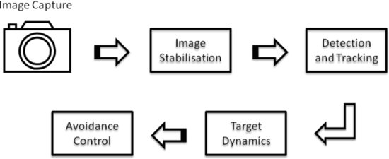
The various components of the system are discussed in the sections which follow.
10.3.1 Image Capture
A number of different image capture systems have been used by the authors for digitizing and recording image measurements in the field. The answer to the question, ‘Which image capture system should be employed in the sense-and-avoid system?’ is strongly influenced by the aircraft platform being used. Some UAV platforms, for example, have a significant amount of inbuilt hardware for capturing images. Accordingly, it is appropriate to describe the image capture system within the context of the rest of the system hardware. Such a description is provided later in this chapter within Section 10.7.
To assist with the processing of digitized image measurements, a model for relating 3D scene elements to their representation on a 2D image has been used. Details of this camera model are discussed next.
10.3.2 Camera Model
The optical sensor is modelled using a first-order approximation of the mapping from a 3D scene to a 2D image, i.e. a pinhole camera model [38, 39]. This model is appropriate in most cases provided that (1) a suitable calibration that accounts for distortion models is known and (2) suitable coordinate transformations can be applied to the image. Other effects that are sufficiently small can be neglected if a high-quality imaging device is used.
Using a pinhole camera model, a point ![]() in 3D space referenced to the camera coordinate frame can be projected onto a point
in 3D space referenced to the camera coordinate frame can be projected onto a point ![]() in a 2D image plane using the following relationship:
in a 2D image plane using the following relationship:
(10.1) 
where f > 0 is the focal length.
More sophisticated camera models could take into consideration all the camera intrinsic parameters, such as the coordinates of the principal point and the ratio of pixel dimension. The use of these more complex models is recommended if millimeter or sub-pixel accuracy is a major concern.
10.4 Image Stabilization
10.4.1 Image Jitter
Image jitter is an undesirable effect caused by the motion of the imaging sensor relative to objects in the scene. As a result, when imaging sensors are mounted on moving platforms, the observed image jitter can be largely attributed to platform motion.
In the presence of image jitter, objects in the camera field-of-view can appear to have motion when in fact they are stationary in the environment. For detection and tracking algorithms that exploit target motion dynamics in the image frame, the motion distortion that image jitter introduces can severely impact performance. The issue is especially significant with narrow field-of-view lenses which tend to exacerbate the effect of image jitter.
There are two main approaches to combating image jitter. The first approach addresses the fundamental cause of image jitter by minimizing the motion of the imaging sensor itself through physical mechanisms such as passive motion-dampening devices or actively stabilized mounts. However, image jitter cannot be completely eliminated by this means, particularly in airborne platforms that are constantly in motion and are subject to unpredictable disturbances such as wind gusts. An alternative/complementary approach is to apply image processing techniques that attempt to realign jitter-affected image frames based on image features or direct measurements of the platform motion.
10.4.2 Jitter Compensation Techniques
Jitter compensation is the process of generating a compensated image sequence where any and all unwanted camera motion is subtracted from the original input. The jitter compensation process can be separated into two components: (a) motion estimation and (b) motion correction. Motion estimation is the main component of an image-based compensation system. Jitter compensation systems may be evaluated based on the performance of the motion estimation module alone, in which case one could use synthetic or calibrated sequences where the inter-frame motions are known. Two distinct approaches for motion estimation are presented in the literature: (a) feature-based motion estimation [40, 41] and (b) global intensity-based motion estimation [42, 43]. The effectiveness of jitter compensation is closely tied to the accuracy of detecting the local motion vectors in order to produce the right global motion vector. Here, three stabilization techniques that have been used in the sense-and-avoid system are presented.
10.4.2.1 Optical Flow
The optical flow technique obtains local velocity vectors of each pixel in the current image frame. These vectors are then used to determine the global translational and rotational motions with the assistance of a motion dynamics model and least squares estimation. A detailed description of the optical flow technique can be found in [44]. The output of optical flow is a velocity field, ![]() , of each pixel at position (i, j). This is the local motion field that is used to compute the global rotational and translational motions. Consider the case where the image frame sequence is purely rotated about a particular rotational centre, (i0, j0), by an angular velocity, ω. The rotational velocity vector,
, of each pixel at position (i, j). This is the local motion field that is used to compute the global rotational and translational motions. Consider the case where the image frame sequence is purely rotated about a particular rotational centre, (i0, j0), by an angular velocity, ω. The rotational velocity vector, ![]() , that describes motion at (i, j) about centre point (i0, j0) can be decomposed into
, that describes motion at (i, j) about centre point (i0, j0) can be decomposed into
![]()
leading to
(10.2) ![]()
Here, θ is the angle of the vector that joins (i0, j0) and (i, j) with respect to a horizontal reference axis. For the case where both translational and rotational motions are present, let the coordinate frame at the rotational centre have translational velocity ú and ![]() , in the vertical and horizontal directions, respectively. Then the velocity
, in the vertical and horizontal directions, respectively. Then the velocity ![]() at any point (i, j), including translational and rotational components, will be given by
at any point (i, j), including translational and rotational components, will be given by
(10.3) ![]()
To determine the global velocities from many local velocity estimates as per equation (10.3), least squares estimation is used. Once the motion is estimated, the correction step consists of displacing the pixel location with a value that is proportional to the estimated translation and rotation.
10.4.2.2 Image Projection Correlation
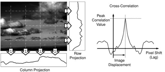
The simplicity of the projection correlation (PrC) algorithm makes it an attractive option for real-time image stabilization, especially when compared to more computationally intensive block-matching methods [45]. The PrC algorithm seeks to characterize a 2D image frame by simpler 1D signals known as the image's row and column projections. The row projection is formed by summing the grey-scale pixel values of each row of the image frame; similarly the column projection is formed from a summation of the image frame columns, as illustrated in Figure 10.3. The translational displacement between two image frames can then be determined from the cross-correlation peak between the projections: row projections are compared to estimate vertical motion and column projections are used to estimate horizontal motion. Enhancements and variations to the basic technique outlined above have been proposed, including methods to improve precision. These variations include passing the projections through a raised cosine filter before correlating and modifications to allow estimation of image rotation [46]. Hybrid techniques that combine image projection and block-matching methods have also been proposed [45].
Figure 10.3 Illustration of the projection correlation technique
10.4.2.3 Inertial Measurement
In contrast to the previous two image-based compensation techniques, the inertial-based method is robust to featureless ‘blue-sky’ conditions that may be encountered in an airborne environment. Inertial-based image stabilization compensates the image sequence by employing motion sensors (typically, gyroscopes and accelerometers packaged in an inertial measurement unit (IMU)) to detect the camera movement. Measurements of camera motion can be translated to equivalent pixel displacements, which can then be used to shift image frames into alignment. This type of image stabilization is hardware-dependent and requires accurate timing and correlation between IMU measurements and captured image frames.
Motion measured with the IMU is translated to motion in pixels based on the following. Let f denote the camera focal length and let ![]() denote the pitch angle displacement at time k, based on the difference between the instantaneous IMU pitch measurement, ϕk, and a fixed reference angle, ϕ0. The vertical pixel displacement caused by a pitching camera motion is then given by
denote the pitch angle displacement at time k, based on the difference between the instantaneous IMU pitch measurement, ϕk, and a fixed reference angle, ϕ0. The vertical pixel displacement caused by a pitching camera motion is then given by ![]() . A similar relationship exists for yawing camera motion; that is,
. A similar relationship exists for yawing camera motion; that is, ![]() , where
, where ![]() is the heading angle displacement at time k. The image frame is corrected for camera rotational motion by shifting the image vertically and horizontally a specific number of pixels, proportional to the values of ρi,k and ρj,k, respectively. (Note that the constant of proportionality depends on camera parameters such as image resolution, field-of-view, etc.). Camera roll motion is compensated directly by applying a basic geometric transformation that rotates the image frame
is the heading angle displacement at time k. The image frame is corrected for camera rotational motion by shifting the image vertically and horizontally a specific number of pixels, proportional to the values of ρi,k and ρj,k, respectively. (Note that the constant of proportionality depends on camera parameters such as image resolution, field-of-view, etc.). Camera roll motion is compensated directly by applying a basic geometric transformation that rotates the image frame ![]() degrees, where ξk denotes the instantaneous IMU roll measurement, and ξ0 denotes a fixed reference angle.
degrees, where ξk denotes the instantaneous IMU roll measurement, and ξ0 denotes a fixed reference angle.
10.5 Detection and Tracking
10.5.1 Two-Stage Detection Approach
A two-stage detection paradigm has become popular over the last few decades for detection of dim, pixel-sized collision targets [11,20--23]. This detection paradigm focuses on the fact that collision threats tend to be small objects without spatial extent, and they are persistent or slowly moving in the image frame. These two characteristics separately lend themselves to different types of signal processing, and hence motivate a two-stage processing approach. These two stages are: (1) an image processing stage (intra-frame) that emphasizes point targets without spatial extent (often incorporating morphological filtering) and (2) a temporal filtering stage (inter-frame) that emphasizes features that are persistent in the scene.
As observed earlier, intra-frame and inter-frame processing stages can work in concert to emphasize and encourage detection of persistent pixel-sized features, whilst rejecting features that either have larger spatial extent (such as cloud artefacts) or features that are only observed temporarily.
10.5.1.1 Stage 1: Morphological Image Pre-processing
Morphological image processing is an intra-frame image enhancement tool that arose out of the seminal work of Georges Matheron and Jean Serra on the analysis of mineral compositions in thin geological cross-sections [47]. They derived a number of mathematical techniques which eventually found application in practical image processing scenarios, one of these applications being aircraft detection.
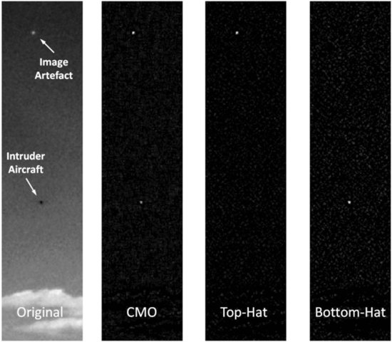
Image morphology techniques help to discriminate genuine intruder aircraft from ‘target-like’ image artefacts that can cause false alarms. Popular morphological filtering techniques include the top-hat, bottom-hat, and close-minus-open transformations [48, 49]. In general, a top-hat approach can be used to identify positive contrast features (features brighter than the local background), whereas a bottom-hat approach can be used to highlight negative contrast features (features darker than the local background). A close-minus-open (CMO) approach combines the power of both the top-hat and bottom-hat operators to simultaneously highlight both positive and negative contrast features.
Analysis of aircraft image data captured by machine vision sensors has shown that distant aircraft predominantly manifest as negative contrast features, suggesting that it is the shadow of the aircraft (rather than the reflected light) that is responsible for the visible contrast [50]. Hence, a bottom-hat filtering approach is particularly suited to identifying distant collision-course aircraft in a sense-and-avoid application.
Let Y ⊕ S and ![]() denote the dilation and erosion respectively of a greyscale image Y by a morphological structuring element S (see [25,51] for more details about the dilation and erosion operations). The structuring element S acts like a cut-off parameter for filtering out features that are too large to be of interest. The bottom-hat transformation is then defined as
denote the dilation and erosion respectively of a greyscale image Y by a morphological structuring element S (see [25,51] for more details about the dilation and erosion operations). The structuring element S acts like a cut-off parameter for filtering out features that are too large to be of interest. The bottom-hat transformation is then defined as ![]() . Figure 10.4 shows an example case where an intruder aircraft is highlighted, whilst an image artefact is suppressed via a bottom-hat filtering approach.
. Figure 10.4 shows an example case where an intruder aircraft is highlighted, whilst an image artefact is suppressed via a bottom-hat filtering approach.
Figure 10.4 Illustration of three common morphological operations on a sample airborne image
10.5.1.2 Stage 2: Track-Before-Detect Temporal Filtering
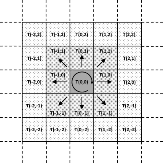
Given that image jitter has been adequately compensated, a potential collision threat can be modelled as a discrete-time process moving across the camera's image plane, gradually transiting across pixels (or remaining at the same pixel). The characteristics of these pixel transitions are related to the expected motion of the collision threat. For example, collision threats will typically appear as slowly moving objects within the image frame, and, hence, the threat is most likely to stay at the same pixel, or move to adjacent pixels. This is graphically represented in Figure 10.5. Two types of inter-frame or temporal filtering approaches have been found to be useful for identifying persistent targets: recursive ad-hoc Viterbi-based filtering approaches and hidden Markov model (HMM) filtering approaches. Both are discussed in what follows.
Figure 10.5 A potential target is most likely to stay in the same pixel or move to an adjacent one over consecutive image frames
Hidden Markov Model Filtering
The HMM filter is an optimal filter for discrete-time processes which involve random transitions between a discrete set of possible locations. If each pixel in the image is considered to be a possible location at which the collision threat could reside, and the target follows a random walk across pixel locations, then the HMM filter can be used to track (and detect) the target's motion in the image [11].
The two key filter design characteristics impacting on detection performance are (1) the model of pixel intensity (in the morphological output) when a target is present in that pixel, denoted ![]() and (2) the model of how the target transitions between pixels, denoted
and (2) the model of how the target transitions between pixels, denoted ![]() .
.
The model of how the target transitions between pixels can be represented by a one-step target motion patch illustrated in Figure 10.5. T(a, b) represents one possible transition where the target moves a pixels in the vertical direction and b pixels in the horizontal direction (note that −2 ≤ a,b ≤ 2 in this particular patch). Given a motion patch, the mean and variance of the expected target motion between frames can be evaluated. The mean expected motion ![]() , and the variance equals
, and the variance equals ![]() .
.
Under the assumption that a target exists, the HMM filter calculates the conditional mean estimate of the target location based on a measurement sequence. (See [52] for a detailed presentation on HMMs.) However, in the collision detection problem, knowledge of target location is arguably secondary to the initial concern of: ‘Is there a collision threat present?’ An intermediate normalization factor within the standard HMM filter is proportional to the probability of the target being present, and hence this factor can be used as the basis of a detection test statistic. That is, the probability ![]() can be evaluated and serve as the metric for a threshold test that reflects a particular collision risk tolerance.
can be evaluated and serve as the metric for a threshold test that reflects a particular collision risk tolerance.
Consider input image frames H pixels in height and W pixels in width, where the image at time step k is denoted by Yk. The output of the HMM filter is another image. Let ![]() denote the output at pixel (i, j) at time step k. The basic HMM filter equations can now be written as:
denote the output at pixel (i, j) at time step k. The basic HMM filter equations can now be written as:
Algorithm 10.1: HMM filter.
For ![]() ,
, ![]() and all k,
and all k,
1. Initialization: At step 0, ![]() (assuming no a priori target information).
(assuming no a priori target information).
2a. Recursion:
![]()
where ![]() and
and ![]() is the probability of observing measurement Yk given the target is at pixel (i, j).
is the probability of observing measurement Yk given the target is at pixel (i, j).
2b. Normalization:
![]()
where ![]() .
.
3. Test statistic:
![]()
where β is a scalar weighting coefficient between zero and one. Note that γ0 = 0.
The test statistic γk for declaring the presence of a target is in the form of an exponentially weighted moving average with weighting coefficient β (experimentally, a weighting of β = 0.9 has been found to produce good detection results). When γk exceeds a predefined threshold (corresponding to a certain probability that a target is present), the HMM filter algorithm considers the target to be present in the image frame. Note that the detection threshold can be selected to achieve a specific design trade-off between detection probability and false alarm rate (a false alarm event occurs when the filter incorrectly declares a target to be present; that is, the test statistic γk crosses the threshold, but there is no target). Higher thresholds reduce the incidence of false alarms, but also lower detection probabilities. The system design objective is to select ![]() and
and ![]() so as to maximize the detection probability for a given false alarm rate (or, equivalently, to minimize the false alarm rate for a given detection probability).
so as to maximize the detection probability for a given false alarm rate (or, equivalently, to minimize the false alarm rate for a given detection probability).
Extensive implementation details for HMM filters are provided in [11,15].
Ad-hoc Viterbi-Based Filtering
One difficult feature of the collision detection problem is that the detection filter must be able to detect collision threats with any heading in the image plane. However, any particular collision threat is likely to have almost constant heading. Thus, if a HMM filter is designed to detect targets with any possible heading, then its detection performance is degraded compared to a HMM filter design with knowledge of the target's specific heading (i.e. with a patch choice corresponding to the target's actual heading and having small variance in heading direction).
For this (and possibly other reasons), several researchers have proposed a different filtering approach that starts from the premise that any specific collision threat can be approximated as a slow-moving target with constant heading. The basic philosophy behind this alternative detection approach is that the uncertainty about target direction can be handled by using a bank of filtering branches (one branch for each of the four compass directions). In this way, if a target is present then it must be, at least partially, detected in one of the filter branches. If the filter branch output is combined in a suitable way, then detection of a target with any heading can be achieved.
It is interesting to note that in this ad-hoc approach, the set of filtering branches replaces the role of transition probability patches in describing the range of possible target headings.
Unfortunately, unlike the HMM filter, there is no simple connection between filter output and the probability of a collision threat being present. However, intuition suggests that the strength of filter returns is closely linked to the likelihood of a target being present, and hence filter outputs can again be used as a test statistic (even if the connection to collision risk is not straightforward).
Let ![]() denote the output at pixel (i, j) of filter branch r, and let Yk(i, j) denote the greyscale level of pixel (i, j) in the input image. Then the basic ad-hoc Viterbi filter equations are:
denote the output at pixel (i, j) of filter branch r, and let Yk(i, j) denote the greyscale level of pixel (i, j) in the input image. Then the basic ad-hoc Viterbi filter equations are:
Algorithm 10.2: Ad-hoc Viterbi filter.
For ![]() ,
, ![]() ,
, ![]() and all k,
and all k,
1. Initialization: At step 0, ![]() .
.
2a. Recursion:
![]()
where ![]() is a branch-specific pixel transition function that is either 1 or 0 to indicate if a transition from pixel (m, n) to pixel (i, j) is allowed, and β is a scalar ‘forgetting’ factor between zero and one.
is a branch-specific pixel transition function that is either 1 or 0 to indicate if a transition from pixel (m, n) to pixel (i, j) is allowed, and β is a scalar ‘forgetting’ factor between zero and one.
2b. Branch combination:
![]() .
.
3. Test statistic:
![]() .
.
When γk exceeds a predefined threshold, the ad-hoc Viterbi filter algorithm considers the target to be present in the image frame. Experimentally, a forgetting factor of β = 0.75 has been found to produce reasonable detection results [30].
Filter Bank Approach
A key deficiency of the ad-hoc Viterbi-based filter is that there is no systematic way to tune filter parameters. Recently, the authors proposed a track-before-detection technique that combined the best features of the ad-hoc Viterbi-based and HMM approaches. In [15], new HMM filter bank techniques were presented that allowed filtering branches to be optimized to a set of distinct behaviours, while the overall filter bank system could be designed to optimize detection performance. For example, one can design a HMM filter bank with four branches, with each branch being a HMM filter with a unique transition model A. In this way, all of the branches can be designed to represent motion in a particular direction (in a systematic manner that is more flexible and better performing than the ad-hoc Viterbi approach). A test statistic can also be devised with this approach which is tightly connected to conflict risk.
The basic HMM filter bank equations are:
Algorithm 10.3: HMM filter bank.
For ![]() ,
, ![]() ,
, ![]() and all k,
and all k,
1. Initialization: At step 0, ![]() (assuming no a priori target information).
(assuming no a priori target information).
2a. Recursion:
![]() ,
,
![]()
where ![]() is the branch-specific transition probability from pixel (m, n) to pixel (i, j) and
is the branch-specific transition probability from pixel (m, n) to pixel (i, j) and ![]() is the probability of observing measurement Yk given the target is at pixel (i, j).
is the probability of observing measurement Yk given the target is at pixel (i, j).
2b. Normalization:
![]() ,
,
![]()
where ![]() .
.
3. Test statistic:
![]() ,
,
![]()
where ![]() , and β is a scalar weighting coefficient between zero and one. Note that
, and β is a scalar weighting coefficient between zero and one. Note that ![]() .
.
Studies have shown that HMM filter bank systems offer superior dim target detection performance compared to other HMM filters. That is, they have higher detection probabilities for a specific false alarm rate [15]. Moreover, studies on sample target image sequences suggest that HMM filter banks have better false alarm rejection than ad-hoc Viterbi filtering approaches (although they may be more sensitive to image jitter) [11].
10.5.2 Target Tracking
After detection has occurred, target position estimates are then passed to a high-level target tracking filter (such as an extended Kalman filter), as illustrated in Figure 10.6. Target tracking is a well-researched field with a rich history, and there are numerous candidate tracking approaches that could be applied at this stage of the sense-and-avoid problem. Hence, specific target tracking approaches will not be discussed in detail in this chapter, but more information can be found in [53].
Figure 10.6 Computer vision-based detection and tracking process
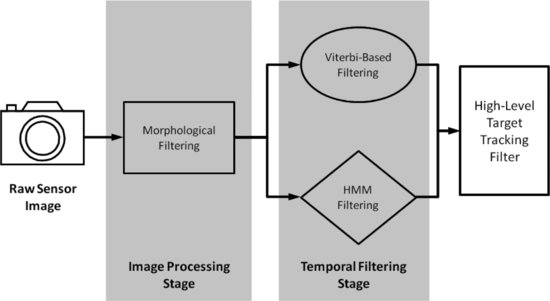
To handle multiple detected targets, one possible approach would be to have a dedicated extended Kalman filter for each potential target, and a track file manager to solve the data association problem [54]. The data association process addresses the issue of whether a newly detected target corresponds to a new target or an existing target. In the latter case, another decision is required if there are multiple existing targets. The track file manager could even assist with higher-level decisions about which objects are genuine collision threats. If a potential target is considered a genuine collision threat, the target image positions from the corresponding track file are then used in the next phase of the sense-and-avoid task – namely, characterization of target dynamics and avoidance control.
10.6 Target Dynamics and Avoidance Control
10.6.1 Estimation of Target Bearing
As discussed in Section 10.3.1, the image must be first transformed from 3D space (characterized by an X,Y,Z coordinate system) into 2D space (represented by just x, y coordinates). Based on the geometry depicted in Figure 10.7, two important parameters of the target with regard to the camera can be extracted; namely the target bearing λ and elevation δ. The bearing represents the angle formed by the vector qxz (the projection of q in the x–z plane) with the z-axis, and the elevation is the angle formed by the vector qyz (the projection of q in the y–z plane) with the z-axis.
Figure 10.7 Camera model and target geometry used for bearing and elevation estimation
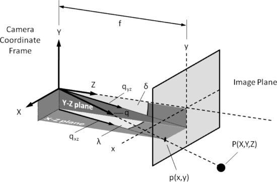
The relative bearing and elevation of the target are estimated as follows:
(10.4) ![]()
where f > 0 is the camera focal length.
It is possible to infer target motion in the image plane by exploiting the bearing and elevation rates ![]() and
and ![]() , respectively. This type of information can be useful in determining whether the target represents a likely collision threat (zero or low angular rates indicate a target is on collision course).
, respectively. This type of information can be useful in determining whether the target represents a likely collision threat (zero or low angular rates indicate a target is on collision course).
10.6.2 Bearing-Based Avoidance Control
The underlying principle behind the proposed avoidance strategy is to move the actuator (camera/aircraft) away from the features (target). This is achieved through a combination of 2D and 3D vision-based control [55, 56]. Let Φmax denote the maximum heading command; let λ represent the current target bearing; let ![]() denote the least desired target bearing; and let c correspond to a positive gain. Then an exponential error function of the form
denote the least desired target bearing; and let c correspond to a positive gain. Then an exponential error function of the form ![]() can be defined, where
can be defined, where
(10.5) ![]()
This error function will be maximum when ![]() , and will decrease in magnitude in an exponential manner away from
, and will decrease in magnitude in an exponential manner away from ![]() , as illustrated in Figure 10.8.
, as illustrated in Figure 10.8.
Figure 10.8 Exponential error function
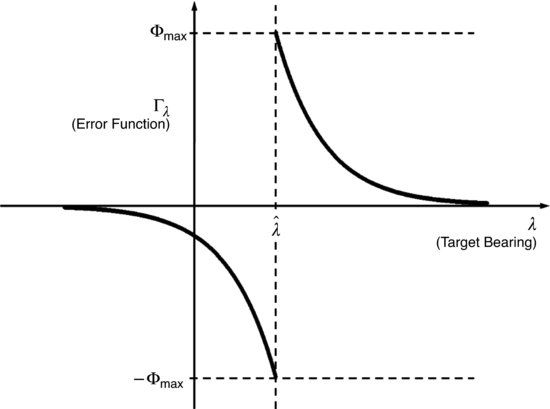
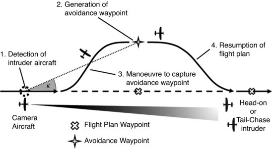
Figure 10.9 Illustration of collision avoidance control strategy
Letting ![]() corresponds to a control strategy that tries to drive the target to the left or right edge of the image frame (or keeps the target away from the centre of the image).
corresponds to a control strategy that tries to drive the target to the left or right edge of the image frame (or keeps the target away from the centre of the image).
Based on the error function Γ, one can develop a control law ![]() , where η is a positive gain and L+ is the pseudo-inverse of an interaction matrix L that relates velocities in 3D space to motion on the 2D image plane. L is dependent on camera intrinsic parameters [57]. The above control law can be used to achieve avoidance behaviour as illustrated in Figure 10.9, where upon detection of an intruder aircraft, an avoidance waypoint at bearing angle
, where η is a positive gain and L+ is the pseudo-inverse of an interaction matrix L that relates velocities in 3D space to motion on the 2D image plane. L is dependent on camera intrinsic parameters [57]. The above control law can be used to achieve avoidance behaviour as illustrated in Figure 10.9, where upon detection of an intruder aircraft, an avoidance waypoint at bearing angle ![]() can be generated and tracked to avert a collision.
can be generated and tracked to avert a collision.
10.7 Hardware Technology and Platform Integration
Avionics and sensor hardware were integrated onto various aircraft platforms to facilitate testing and evaluation of the proposed sense-and-avoid system. An important aspect of this activity involved the development of target/intruder platforms that play the role of a non-cooperative collision-course aircraft, as well as camera platforms that capture image data for either online or offline post-processing. The key principles that guided the design of the platform architectures included making subsystems modular, reusable, and that exploit commercial-off-the-shelf (COTS) components where possible.
The key innovations in the platform architectures are the approaches to (1) precisely associate captured image data with the corresponding aircraft state information measured at the time of image capture and (2) real-time image processing.
Figure 10.10 Boomerang UAV target platform

10.7.1 Target / Intruder Platforms
The main function of the target platform is to act as the ‘aircraft to avoid’ in collision scenarios and to precisely log its own state information. Two different types of target platforms have been employed: (i) a Boomerang UAV and (ii) a piloted Cessna 182 light aircraft.
10.7.1.1 Boomerang UAV
The UAV target platform is a Boomerang 60 model airplane manufactured by Phoneix Models. A photograph of the platform is shown in Figure 10.10. The model airplane measures 1.5 m from nose to tail and has a wingspan of 2.1 m. It is powered by an OS 90 FX engine driving a 15 by 8 inch propeller.
System Architecture
The Boomerang carries the highly modular UAV base system architecture illustrated in Figure 10.11. It relies on the MicroPilot 2128's autopilot and suite of onboard sensors for flight control and navigation. The UAV can be operated autonomously or flown manually under radio control (RC). The Boomerang UAV provides basic unmanned flight capabilities, and a detailed breakdown of the system components is given in Table 10.1.
Figure 10.11 UAV base system architecture
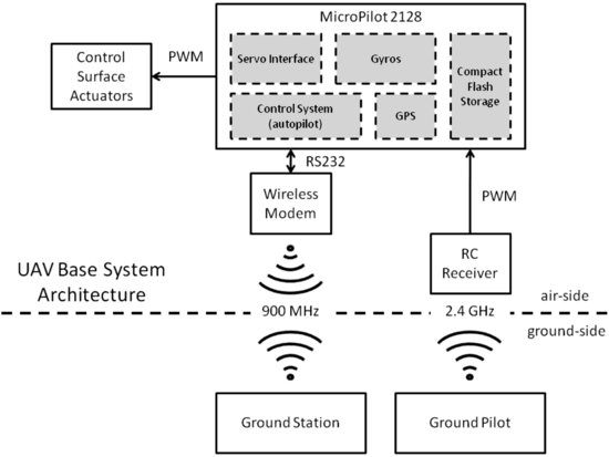
Table 10.1 Boomerang UAV system configuration
| System component | Hardware selection |
| Inertial measurement sensor | MicroPilot® MP2128 gyros |
| Flight controller | MicroPilot® MP2128 control system |
| GPS sensor | MicroPilot® MP2128 GPS navigation |
| Communications with ground station | Microhard Systems Spectra 920A wireless modem |
| Communications with ground pilot | Spektrum AR9000 SM2 9-channel RC receiver |
10.7.1.2 Piloted Cessna 182 Light Aircraft
The light aircraft target platform is a standard Cessna 182 aeroplane. During flight tests it carries a NovAtel DL-V3 GNSS receiver for logging aircraft state information.
10.7.2 Camera Platforms
The camera platforms have two distinct roles: (1) image data collection and (2) onboard real-time sense-and-avoid processing. The UAV camera platform is equipped to perform only the data collection role, whereas the light aircraft camera platform is capable of full in-flight data collection and closed-loop sense-and-avoid testing.
10.7.2.1 Flamingo UAV
The UAV camera platform is a Flamingo UAV manufactured by Silvertone [58]. It is powered by a 26-cc two-stroke Zenoah engine driving a 16 by 6 inch propeller and is shown in Figure 10.12.
Figure 10.12 Flamingo UAV camera platform
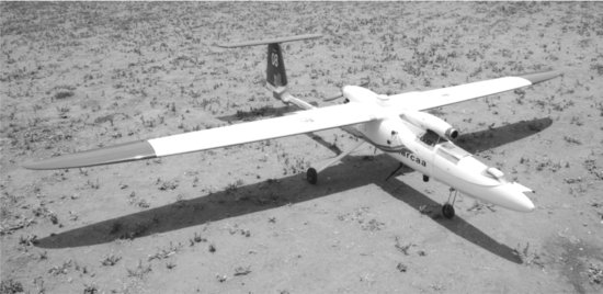
Figure 10.13 Flamingo UAV system architecture

System Architecture
The Flamingo system design exploits the base system architecture of the Boomerang target platform for general flight control. In addition, it has a separate and independent vision payload system for data capturing (but no onboard image processing capability), as illustrated in Figure 10.13. The vision payload system employs dedicated high-quality inertial and position sensors to provide timely (high update rate) and precise state information critical for image stabilization. A custom real-time operating system ensures that recorded image frames are associated with aircraft state data at precisely the point when the camera is triggered. In particular, a multi-data source synchronization process was developed around a global triggering pulse to coordinate the simultaneous capture of image, global positioning system (GPS), and IMU data. The system has the capacity to record 1024 by 768 pixel image frames (at 8 bits per pixel bit depth) and associated state data to a solid state drive at a rate of up to 15 frames per second (approximately 12 Mb/s sustained writing to disk). Furthermore, the vision payload system can be activated/deactivated remotely from the ground station. A detailed breakdown of the system components is given in Table 10.2.
System Configuration
Table 10.2 Flamingo UAV system configuration
| System component | Hardware selection |
| Vision sensor | Basler Vision Technologies Scout Series scA1300-32fc area scan camera |
| Inertial measurement sensor | Atlantic Inertial Systems SilMU04® |
| Flight controller | MicroPilot® MP2128 control system |
| GPS sensor | NovAtel OEMV-1 |
| Communications with ground station | Microhard Systems Spectra 920A wireless modem (2x) |
| Communications with ground pilot | Spektrum AR9000 SM2 9-channel RC receiver |
| Flight computer | Digital-Logic® SM855 PC/104; Intel® Pentium® M 1.8 GHz processor; 1 GB SODIMM DDR RAM; Linux Debian operating system with customized kernel for real-time processing |
| Image data storage | OCZ Technology SATA II 2.5 |
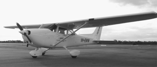
10.7.2.2 Piloted Cessna 172 Light Aircraft
The light aircraft camera platform is a custom-fitted Cessna 172 light aircraft, which is shown in Figure 10.14. The design, manufacture, maintenance, and operation of this cost-effective flight testing platform are detailed in [59]. The Cessna 172 has been equipped with onboard data capturing and real-time image processing capabilities to produce a system suitable for complete closed-loop sense-and-avoid testing; that is, a system capable of automatically (1) detecting intruder aircraft; (2) issuing avoidance control commands; and (3) executing control commands, all without external pilot or ground station interaction.
Figure 10.14 Light aircraft camera platform
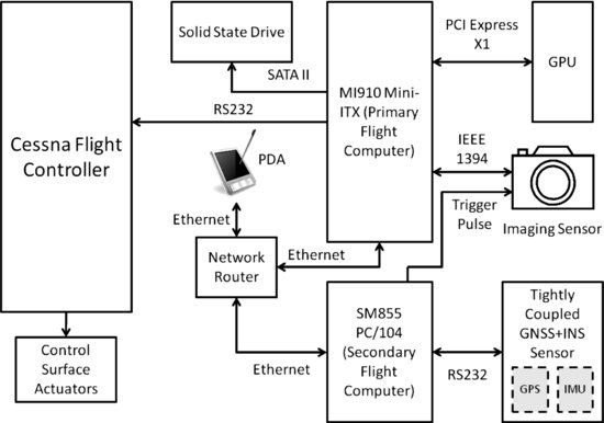
Basic System Architecture
The data capturing system onboard the Cessna 172 is based on the vision payload system of the Flamingo. The introduction of graphic processing unit (GPU) hardware, as illustrated in Figure 10.15, provides a real-time image processing capability that was absent in the Flamingo. Computationally intensive tasks such as image stabilization and target detection are handled entirely by the GPU, allowing 1024 by 768 pixel image frames (at 8 bit per pixel bit depth) to be processed at a rate of up to 15 frames per second. Other processing tasks are distributed across two flight computers, with one computer connected directly to the aircraft flight controller for automated avoidance control. A tightly coupled GNSS and INS sensor suite provides high-quality aircraft state information, and the overall sense-and-avoid system can be managed and monitored via a compact personal digital assistant (PDA) interface. The image sensor is mounted onto the aircraft wing strut using a certified custom-made bracket. A detailed breakdown of the system components is given in Table 10.3.
Figure 10.15 Cessna system architecture
Basic System Configuration
Table 10.3 Piloted Cessna 172 light aircraft system configuration
| System component | Hardware selection |
| Vision sensor | Basler Vision Technologies Scout Series scA1300-32fc area scan camera |
| Inertial measurement sensor | iMAR IMU-FSAS* |
| GPS sensor | NovAtel OEMV-3* |
| Primary flight computer | Backplane Systems Technology MI910 Mini-ITX; Intel® Core 2 Duo 2.4 GHz processor; 2 GB SDRAM; Linux Debian operating system |
| Secondary flight computer | Digital-Logic® SM855 PC/104; Intel® Pentium® M 1.8 GHz processor; 1 GB SODIMM DDR RAM; Linux Debian operating system with customized kernel for real-time processing |
| Image processing GPU | Gigabyte™ NVIDIA® GeForce® 9600 GT; 512 MB GDDM1R3 RAM |
| Image data storage | OCZ Technology SATA II 2.5 |
| *This sensor is part of a NovAtel SPAN (Synchronized Position, Attitude and Navigation) product (tightly coupled GNSS+INS sensor) in a ProPack-V3 enclosure. | |
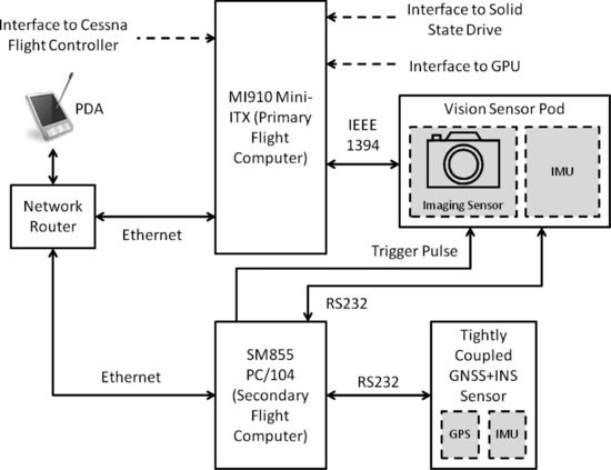
Vision Sensor Pod Architecture
A variation of the basic system architecture has been developed to accommodate a sensor pod configuration as shown in Figure 10.16. The sensor pod provides an upgrade to the basic camera mounting bracket solution and facilitates the co-location of an IMU with the vision sensor for image stabilization purposes.
Figure 10.16 Sensor pod system architecture
10.7.3 Sensor Pod
To minimize jitter effects and enhance the quality of state-based image stabilization, a self-enclosed weatherproof sensor pod was manufactured. This sensor pod featured improved mechanical vibration characteristics and the capacity to house an independent IMU alongside the vision sensor.
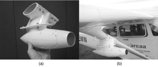
A rapid prototyping 3D printer (Dimension SST 786 [60]) was utilized to fabricate the core pod structure components through a fused deposition modelling (FDM) process from a base material of acrylonitrile butadiene styrene (ABS) plastic. These core components, as illustrated in Figure 10.17, were then reinforced with a combination of woven glass, carbon, and hybrid Kevlar sheet material bonded with epoxy resin (Araldite 3600) in order to withstand the stresses of flight. The surface of the reinforced structure was smoothed through the application of fairing compound, which was then sanded and sprayed with 2-pack automotive paint to create a polished streamlined finish. Figure 10.18(a) shows a close-up of the painted pod components fully assembled. Figure 10.18(b) illustrates the pod attached to the aircraft in flight configuration with camera and IMU sensors integrated. Formal airworthiness certification of the sensor pod was obtained in compliance with regulations from the Australian Civil Aviation Safety Authority.
Figure 10.17 Sensor pod components
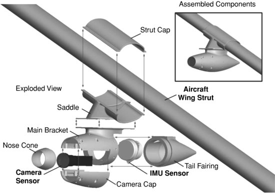
Figure 10.18 Sensor pod (a) assembled and (b) mounted on aircraft
10.7.4 Real-Time Image Processing
Real-time performance was achieved by exploiting the parallelism provided by GPUs and the Compute Unified Device Architecture (CUDA) [61], a NVIDIA application programming interface (API). The image processing algorithm performs several sequential operations transferring data between the CPU host and GPU device memory. The implementation uses CUDA kernels, which are a special type of C function that are executed N times in parallel by N different CUDA threads. Threads are grouped into blocks, and communicate only with other threads in the same block using quick access L1 cache type memory.
The block size, and, therefore, the number of threads per block, is limited and can be optimized to suit (1) the task, (2) the amount of cache memory required, and (3) the particular GPU device. The performance of the GPU implementation is closely related to (1) the number of under-utilized warps; (2) the number of multiprocessors and blocks per multiprocessor specific to the particular GPU device; and, finally, (3) the number of threads per block (ideally always a multiple of 32). The latter should be chosen to be as high as possible, limited obviously by the GPU compute capability [61] and available registers.
Several laboratory experiments were conducted to evaluate the scalability and performance of various GPU hardware solutions for image processing. Figure 10.19 illustrates the speed (in terms of frames processed per second) at which various COTS NVIDIA GPU cards were able to execute the detection algorithm.
Figure 10.19 Frame processing rate of detection algorithm vs. number of microprocessors in candidate GPU cards
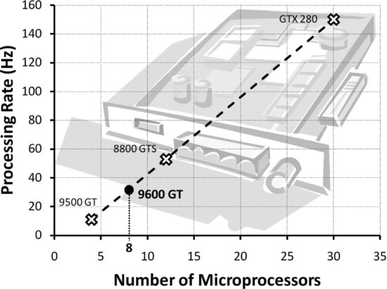
A near-linear relationship was found between the number of microprocessors and the raw image processing speed (excluding data transfer and disk read/write overheads). Substantial processing rates of up to 150 Hz or frames per second (1024×768 pixel image; 8 bit per pixel bit depth) have been achieved using a NVIDIA GeForce GTX 280, but the high power consumption (236 W) of this card precludes its practical use in UAV platforms. Instead, a NVIDIA GeForce 9600 GT GPU (low-power version) has been tested which is considered to have the best processing speed/power consumption trade-off. It has 8 microprocessors and consumes only 59 W of power. This card is used in the flight-ready hardware configuration and can achieve raw processing rates of up to 30 frames per second, which is sufficient for real-time target detection.
Table 10.4 Flight testing schedule
10.8 Flight Testing
Flight tests were undertaken to collect collision-course image data and to evaluate the performance of the proposed sense-and-avoid system under realistic operating conditions in phases of progressively increasing complexity and autonomy. This testing philosophy is reflected in the flight testing schedule shown in Table 10.4. The first three phases of testing have been completed, and the ultimate goal is to have fully autonomous UAVs demonstrating closed-loop sense-and-avoid capabilities (Phase V).
10.8.1 Test Phase Results
Phase I testing involved establishing a baseline detection range performance for the sense-and-avoid system using a 51° by 40° field-of-view (FOV) lens. For this purpose, UAV platforms were deployed and recreated various ‘head-on’ collision scenarios to collect relevant image data for offline post-processing. Subsequently, detection distances ranging from 400 m to 900 m were obtained using the HMM detection approach. Taking the ‘worst-case’ scenario and approximating the UAV closing speed at 50 m/s, this represents an approximate 8 s warning ahead of impact that the baseline sense-and-avoid system can achieve. This approaches the 12.5 s response time that human pilots need (after detecting the threat) in order to safely avoid a collision [62].
In Phase II testing, a narrower FOV lens (approximately 17° by 13°) was selected to improve detection range and the system was operated for the first time in-flight with all processing carried out onboard. The system demonstrated the ability to detect targets out to distances ranging from 3 km to 5 km. Even with the increased closing speeds (approximately 100 m/s) of the light aircraft platforms, the detection distances represent timely warnings ahead of impact that exceed the minimum response time recommended for human pilots.
Finally, in Phase III testing the system ultimately demonstrated full closed-loop sense-and-avoid functionality. Future test phases will work towards reproducing current closed-loop capabilities onboard UAV platforms.
10.9 Future Work
One of the key impediments to practical realization of computer vision-based sense-and-avoid systems with existing technology is the incidence of false alarms that could cause unnecessary avoidance responses. It is imperative, therefore, to refine existing algorithms (or find new ones) which can minimize false alarm events. There may be alternatives to conventional morphological filtering front-ends, for example, which can provide the necessary improvements. Adaptation of the morphological processing to suit the application at hand is another avenue which merits further investigation. Adaptation might also prove useful within the HMM filtering domain. For example, one could bring additional filter branches online when needed, and discard them when not needed. This added flexibility might reduce the computational burden and further enhance detection performance.
There is also room for improvement in the way the image processing and control portions of the sense-and-avoid system are implemented. One might be able to make performance gains by implementing the processing algorithms using the OpenCL programming framework/ language. This could also make the code more portable to other GPUs, since the CUDA-based designs used for realization of the proposed sense-and-avoid system are only supported on hardware from NVIDIA.
Finally, it is important to point out that a key limitation of UAVs is their inability to accommodate large, heavy, or high-power payloads. A promising area of future work, then, is the miniaturization of an entire closed-loop sense-and-avoid system, such that it can fit inside a relatively small UAV.
10.10 Conclusions
This chapter has outlined a number of key advantages to realizing a sense-and-avoid system based on computer vision in the optical range. Optical camera-based sensing systems are relatively low in cost, volume, power, and weight compared to alternatives such as radar and TCAS. Vision-based systems also do not have to rely on (possibly non-existent) cooperation from other aircraft.
Although optical sense-and-avoid systems have a number of key advantages, they also bring with them an array of challenges. Since aircraft generally travel at relatively high speeds, one has to detect targets when they are a long distance away and which occupy only a minute fraction of the image frame. Under such challenging circumstances, accurate and timely detection of targets is difficult enough, even without factoring in the dynamic and unpredictable airborne environment. This environment is characterized by an abundance of interfering elements such as clouds and other weather-dependent phenomena that conspire to hide genuine targets and introduce target-like artefacts. A system that does not account for these factors is likely to demonstrate an unacceptably high incidence of false alarms. Finally, optical sense-and-avoid systems also rely on sophisticated image processing methods which are, generally, computationally intensive.
This chapter has shown that significant progress has been made towards overcoming the challenges associated with using computer vision for sense-and-avoid. Elegant new processing techniques involving morphological filtering and hidden Markov model filter banks are particularly promising. Tests using realistic collision-course image data have shown that these techniques are effective in sensing airborne targets if the cloud and background clutter is not excessive. Furthermore, flight trials have demonstrated that real-time processing can be achieved and that closed-loop sense-and-avoid functionality is possible. The existing technology does, however, suffer from a moderate number of false alarms, which would trigger unnecessary avoidance actions. It is believed that if false alarm events associated with cloud artefacts could be eliminated, then the resulting system performance would be acceptable for the purposes of routine automated sense-and-avoid.
Acknowledgements
This chapter was supported under the Australian Research Council's Linkage Projects funding scheme (Project Number LP100100302) and the Smart Skies Project, which is funded, in part, by the Queensland State Government Smart State Funding Scheme.
References
1. M. DeGarmo, ‘Issues concerning integration of unmanned aerial vehicles in civil airspace’, 2004.
2. US Army UAS Center of Excellence, ‘ “Eyes of the Army” U.S. Army Roadmap for Unmanned Aircraft Systems 2010–2035’, 2010.
3. W. Graham and R. H. Orr, ‘Separation of air traffic by visual means: an estimate of the effectiveness of the see-and-avoid doctrine’, Proceedings of the IEEE, pp. 337–361, March 1970.
4. P. Zarchan, Tactical and Strategic Missile Guidance, 4th edn. American Institute of Aeronautics and Astronautics, Reston, VA, 2002.
5. N. Shneydor, Missile Guidance and Pursuit: Kinematics, Dynamics and Control, Horwood Publishing, Chichester, 1998.
6. Australian Transport Safety Bureau, ‘Limitations of the See-and-Avoid Principle’, 1991.
7. T. Williamson and N. Spencer, ‘Development and operation of the Traffic Alert and Collision Avoidance System (TCAS)’, Proceedings of the IEEE, 77(11), 1735–1744, 1989.
8. International Civil Aviation Organization, ‘Annex 6 to the Convention on International Civil Aviation – Operation of Aircraft – Part I – International Commercial Air Transport – Aeroplanes’, in Annexes to the Convention on International Civil Aviation, pp. 6–10, 2001.
9. Forecast International [Online], www.forecastinternational.com/Archive/es/es0077.doc, January 2007.
10. Office of the Secretary of Defense, ‘Airspace Integration Plan for Unmanned Aviation’, 2004.
11. J. Lai, L. Mejias, and J. J. Ford, ‘Airborne vision-based collision-detection system’, Journal of Field Robotics, 28(2), 137–157, 2011.
12. C. Geyer, S. Singh, and L. Chamberlain, ‘Avoiding Collisions Between Aircraft: State of the Art and Requirements for UAVs operating in Civilian Airspace’, Robotics Institute, 2008.
13. G. Fasano et al., ‘Multi-sensor-based fully autonomous non-cooperative collision avoidance system for unmanned air vehicles’, Journal of Aerospace Computing, Information, and Communication, 5, 338–360, 2008.
14. Y. Bar-Shalom, H. M. Shertukde, and K. R. Pattipati, ‘Use of measurements from an imaging sensor for precision target tracking’, IEEE Transactions on Aerospace and Electronic Systems, 25(6), 863–872, 1989.
15. J. Lai and J. J. Ford, ‘Relative entropy rate based multiple hidden Markov model approximation’, IEEE Transactions on Signal Processing, 58(1), 165–174, 2010.
16. J. Keller, Military and Aerospace Electronics [Online], http://www.militaryaerospace.com/index/display/mae-defense-executive-article-display/0220059175/articles/military-aerospace-electronics/executive-watch-2/2010/10/sierra-nevada_corp.html, October 2010.
17. B. Karhoff, J. Limb, S. Oravsky, and A. Shephard, ‘Eyes in the domestic sky: an assessment of sense and avoid technology for the army's “Warrior” unmanned aerial vehicle’, in Proceedings of the IEEE Systems and Information Engineering Design Symposium, Charlottesville, VA, pp. 36–42, 2006.
18. D. Maroney, R. Bolling, M. Heffron, and G. Flathers, ‘Experimental platforms for evaluating sensor technology for UAS collision avoidance’, in Proceedings of the IEEE/AIAA Digital Avionics Systems Conference, Dallas, TX, pp. 5C1-1–5C1-9, 2007.
19. W. Rosenkrans, ‘Detect, sense and avoid’, AeroSafety World, pp. 34–39, July 2008.
20. J. Arnold, S. Shaw, and H. Pasternack, ‘Efficient target tracking using dynamic programming’, IEEE Transactions on Aerospace and Electronic Systems, 29(1), pp. 44–56, 1993.
21. Y. Barniv, ‘Dynamic programming solution for detecting dim moving targets’, IEEE Transactions on Aerospace and Electronic Systems, AES-21(1), 144–156, 1985.
22. T. Gandhi et al., ‘Detection of obstacles in the flight path of an aircraft’, IEEE Transactions on Aerospace and Electronic Systems, AES-39(1), 176–191, 2003.
23. T. Gandhi et al., ‘Performance characterization of the dynamic programming obstacle detection algorithm’, IEEE Transactions on Image Processing, 15(5), 1202–1214, 2006.
24. S. D. Deshpande, M. H. Er, R. Venkateswarlu, and P. Chan, ‘Max-mean and max-median filters for detection of small targets’, in Proceedings of the Signal and Data Processing of Small Targets, Denver, CO, pp. 74–83, 1999.
25. E. R. Dougherty and R. A. Lotufo, Hands-on Morphological Image Processing, SPIE Optical Engineering Press, Bellingham, MA, 2003.
26. L. JiCheng, S. ZhengKang, and L. Tao, ‘Detection of spot target in infrared cluster with morphological filter’, in Proceedings of the IEEE National Aerospace and Electronics Conference, Dayton, OH, pp. 168–172, 1996.
27. Z. Zhu, Z. Li, H. Liang, B. Song, and A. Pan, ‘Grayscale morphological filter for small target detection’, in Proceedings of the SPIE International Symposium on Optical Science and Technology: Infrared Technology and Applications, San Diego, CA, pp. 28–34, 2000.
28. M. Zeng, J. Li, and Z. Peng, ‘The design of top-hat morphological filter and application to infrared target detection’, Infrared Physics & Technology, 48(1), 67–76, 2006.
29. N. Yu, H. Wu, C. Wu, and Y. Li, ‘Automatic target detection by optimal morphological filters’, Journal of Computer Science and Technology, 18(1), 29–40, 2003.
30. R. Carnie, R. Walker, and P. Corke, ‘Image processing algorithms for UAV “Sense and Avoid” ’, in Proceedings of the IEEE International Conference on Robotics and Automation, Orlando, FL, pp. 2848–2853, 2006.
31. S. J. Davey, M. G. Rutten, and B. Cheung, ‘A comparison of detection performance for several track-before-detect algorithms’, EURASIP Journal on Advances in Signal Processing, 2008, 1–10, 2008.
32. S. M. Tonissen and R. J. Evans, ‘Performance of dynamic programming techniques for track-before-detect’, IEEE Transactions on Aerospace and Electronic Systems, 32(4), 1440–1451, 1996.
33. M. G. S. Bruno, ‘Bayesian methods for multiaspect target tracking in image sequences’, IEEE Transactions on Image Processing, 52(7), 1848–1861, 2004.
34. M. G. S. Bruno and J. M. F. Moura, ‘Multiframe detector/tracker: optimal performance’, IEEE Transactions on Aerospace and Electronic Systems, 37(3), 925–945, 2001.
35. M. G. S. Bruno and J. M. F. Moura, ‘The optimal 2D multiframe detector/tracker’, International Journal of Electronics and Communications, 53(6), 1–17, 1999.
36. G. D. Forney Jr., ‘The Viterbi algorithm’, Proceedings of the IEEE, 61(3), 268–278, 1973.
37. L. Mejias, S. McNamara, and J. Lai, ‘Vision-based detection and tracking of aerial targets for UAV collision avoidance’, in Proceedings of the IEEE/RSJ International Conference on Intelligent Robots and Systems, Taipei, 2010.
38. R. Hartley and A. Zisserman, Multiple View Geometry in Computer Vision, 2nd edn, Cambridge University Press, New York, 2004.
39. Y. Ma, S. Soatto, J. Kosecka, and S. S. Sastry, An Invitation to 3-D Vision: From Images to Geometric Models, Springer-Verlag, New York, 2004.
40. J.-Y. Chang, W.-F. Hu, M.-H. Cheng, and B.-S. Chang, ‘Digital image translational and rotational motion stabilization using optical flow technique’, IEEE Transactions on Consumer Electronics, 108–115, 2002.
41. A. Censi, A. Fusiello, and V. Roberto, ‘Image stabilization by features tracking’, in Proceedings of the International Conference on Image Analysis and Processing, Venice, pp. 665–667, 1999.
42. V.-N. Dang, A.-R. Mansouri, and J. Konrad, ‘Motion estimation for region-based video coding’, in Proceedings of the International Conference on Image Processing, Washington, DC, pp. 189–192, 1995.
43. S. Erturk and T. J. Dennis, ‘Image sequence stabilisation based on DFT filtering’, IEE Proceedings on Vision, Image and Signal Processing, 147 (2), 95–102, 2000.
44. B. K. P. Horn and B. G. Schunck, ‘Determining optical flow’, Artificial Intelligence, 17(1–3), 185–203, 1981.
45. G. Ren, P. Li, and G. Wang, ‘A novel hybrid coarse-to-fine digital image stabilization algorithm’, Information Technology Journal, 9(7), 1390–1396, 2010.
46. S. B. Balakirsky and R. Chellappa, ‘Performance characterization of image stabilization algorithms’, Real-Time Imaging, 2(5), 297–313, 1996.
47. J.-P. Serra, Image Analysis and Mathematical Morphology, Academic Press, New York, 1982.
48. R. C. Gonzalez, R. E. Woods, and S. L. Eddins, ‘Morphological image processing’, in Digital Image Processing Using MATLAB, Pearson-Prentice Hall, Upper Saddle River, NJ, pp. 334–377, 2004.
49. D. Casasent and A. Ye, ‘Detection filters and algorithm fusion for ATR’, IEEE Transactions on Image Processing, 6(1), 114–125, 1997.
50. C. Geyer, D. Dey, and S. Singh, ‘Prototype Sense-and-Avoid System for UAVs’, Robotics Institute, 2009.
51. P. Soille, ‘Opening and closing’, in Morphological Image Analysis: Principles and Applications, Springer, Berlin, pp. 105–137, 2003.
52. R. J. Elliott, L. Aggoun, and J. B. Moore, in B. Rozovskii and G. Grimmett (eds), Hidden Markov Models: Estimation and Control, Springer, Berlin, 1995.
53. Y. Bar-Shalom, X.-R. Li, and T. Kirubarajan, Estimation with Applications to Tracking and Navigation: Theory, Algorithms and Software, John Wiley & Sons, New York, 2001.
54. Y. Bar-Shalom and T. E. Fortmann, Tracking and Data Association, Academic Press, Boston, 1988.
55. A. C. Sanderson and L. E. Weiss, ‘Adaptive visual servo control of robots’, in A. Pugh (ed.), Robot Vision, IFS Publications, pp. 107–116, 1983.
56. M. W. Spong, S. Hutchinson, and M. Vidyasagar, Robot Modeling and Control, John Wiley & Sons, Hoboken, NJ, 2006.
57. F. Chaumette and S. Hutchinson, ‘Visual servoing and visual tracking’, in B. Siciliano and O. Khatib (eds), Handbook of Robotics, Springer, Berlin, pp. 563–582, 2008.
58. B. Young, Silvertone UAV [Online], http://www.silvertoneuav.com, March 2011.
59. D. Greer, R. Mudford, D. Dusha, and R. Walker, ‘Airborne systems laboratory for automation research’, in Proceedings of the International Congress of the Aeronautical Sciences, Nice, pp. 1–9, 2010.
60. Stratasys, ‘Dimension BST 768/SST 768 User Guide’, 2006.
61. NVIDIA, ‘NVIDIA CUDA C Programming Guide Version 3.2’, 2010.
62. Federal Aviation Administration, ‘FAA Advisory Circular: Pilots’ role in collision avoidance’, 1983.